Correction on Sep 1:
Some zero/pole numbers in the original entry was incorrect, so I made some corrections below.
Specifically, ILPD has zp=([71mHz;72mHz;2.7k],[3.1;3.4;130;2.3k]) (130 and 2.7k were swapped in the original entry). Plots were updated accordingly.
Summary:
- The outer loop OLTF was measured to be very small.
- That's because the inner loop whitening compensation is NOT implemented in the prototype board. This needs to be implemented.
- (This is implemented in the original (old) second loop board.)
What's done and found:
- Polarity of the board was found to be wrong so I and Fil pulled the chassis and flipped the sign using a jumper.
-
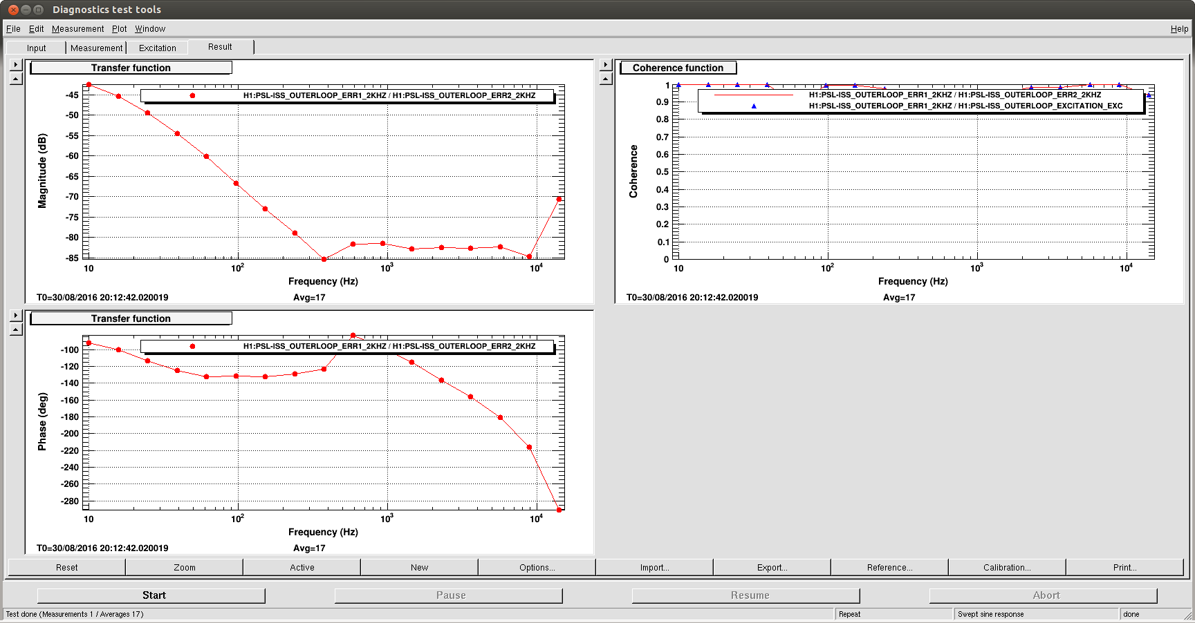
After the polarity fix, I measured the OLTF of the outer loop servo with 2W PSL output, AC coupling servo enabled, and the maximum board gain of 45.6dB (first attachment).
- Don't try to learn too much from this "measurement" as I was saturating the electronics, this is not meant to be a precise measurement. But the point is that this is very, very small.
-
Unfortunately it turns out that this is what you get when you don't implement the zero-pole correction that I mentioned in point 2. of alog 29293 and its attachment entry.
- Gist of it is that the intensity noise sensing gain for the inner loop PD is huge for f>3Hz because of double 70mHz zero, and the outer loop board gain needs to be even bigger in order for the outer loop to have any reasonable gain.
- After the above mentioned measurement, negative leg of the outer loop differential output was found to be grounded to the chassis on the output connector. This is not why the OLTF is very small, but we need to fix it.
These things were mostly done during Tuesday maintenance.
Some more explanation:
Since the outer loop injects its signal to the inner loop error point, OLTF of outer loop is basically the ratio of two transfer functions, one from RIN to the output of the outer loop servo board (H_OLBoard) and the other from RIN to the inner loop error point (H_ILPD):
OLTF_OL=H_OLBoard/H_ILPD.
As I noted before (alog 26879 and an entry attached later to that one), the inner loop diode is equivalent of 660 Ohm DC trans impedance and zp=([71mHz;72mHz;2.7k],[3.1;3.4;130;2.3k]) . DC output of this inner loop diode is about 1.6V differential (measured). For details you need to look at D1001998.
H_IL = 1.6[V]*zp([71mHz;72mHz;2.7k],[3.1;3.4;130;2.3k]).
OTOH, outer loop trans impedance amplifier doesn't have any coloring in the new prototype (the old one has this compensation, see D1300639), and each diode outputs about 130mV or so at 2W. There are four PDs, so the sum of all PDs at DC is about 520mV at 2W. The outer loop chassis has a flat gain of 3, a variable gain (VGA) with -12.8 to 45.6dB range, and a servo filter SERVO=zp([600;9k],[20,20,380]) with the DC gain of 1 (see alog 29293). (There should be another factor of 2 from SE to DIFF conversion, but the negative leg of DIFF is grounded, so this is not there at the moment.). There's also a MC pole (9k) in H_OLBoard.
H_OLBoard(2W) = 0.52[V]*3*IMC*VGA*SERVO = RIN*1.6[V]*VGA*zp([600],[20,20,380]).
Combining these,
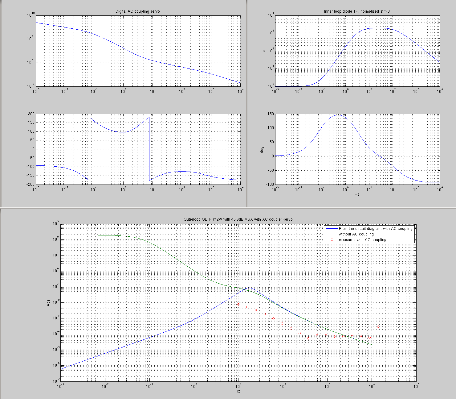
OLTF_OL @2W = H_OLBoard@2W/H_ILPD ~ zp([71mHz;72mHz;2.7k],[3.1;3.4;130;2.3k])/zp(600, [20;20;380])/VGA.
Thing is, H_IL is absolutely huge at 3Hz and higher due to double 70mHz zeros, and the outer loop board as of now doesn't have the gain necessary to keep the UGF at some kHz.
Second attachment bottom shows the above theoretical OLTF at 2W with the maximum (45.6dB) VGA and the measured data. Remember that the "measured" is no good measurement because it was saturating, but nevertheless you can see that the measurement is not totally unreasonable.
It's clear to that we need something in the outer loop to counter 70mHz double zeros.
Implementing that would also help AC coupling. As of now, the AC coupling is already sort of aggressive, but not aggressive enough. If I bring up the blue curve in the second plot bottom by 80dB or so to set the outer loop higher UGF at 2kHz, the lower UGF would become .2Hz or so, that might not be good enough of an AC coupling.