daniel.hoak@LIGO.ORG - posted 17:16, Friday 25 May 2012 (2962)
Picomotor breakout boxes
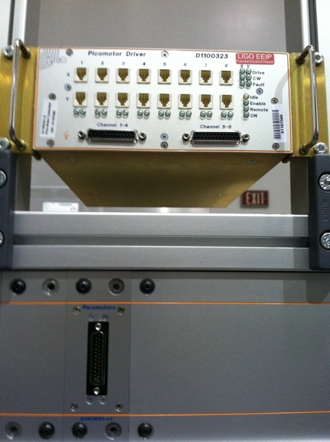
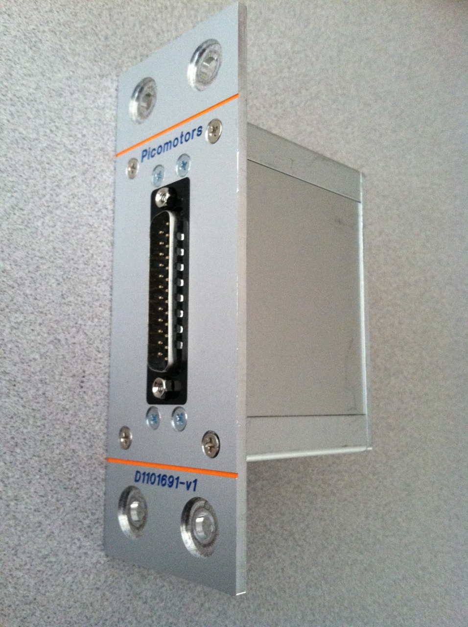
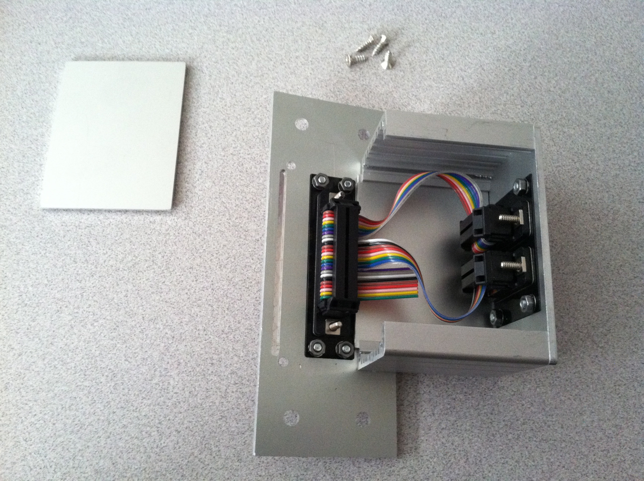
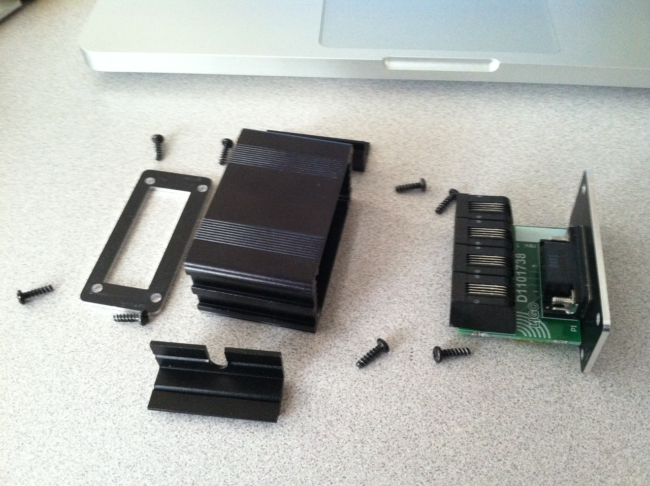
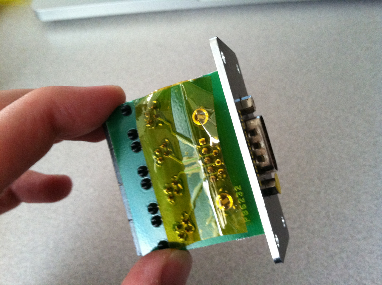
For posterity, I wanted to show how the picomotor signal from the driver box is broken up into the individual DOF signals. In the pictures attached, the signal from the driver box goes to the Picomotor Break-out Feedthrough Panel [image 1]. This box takes the DB25 cable and splits it into two DB9 cables [2,3]. These DB9 cables go to a Picomotor Breakout Box, which rests inside the table on the cable tray. This box has a PCB which splits the signals on the DB9 cable into four 4-pin RJ45 connectors, which are the pitch and yaw signals for two different picomotor assemblies [4,5].
Images attached to this report