keita.kawabe@LIGO.ORG - posted 16:44, Tuesday 13 September 2016 (29676)
ISS second loop today (Daniel, Keita)
Some features were added in the model (first attachment):
-
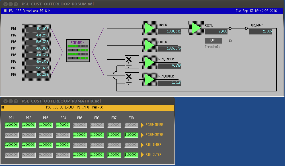
Indivisual digital PD signals are fed to PSL-ISS_OUTERLOOP_PDSUMINNER, PDSUMOUTER, RIN_INNER and RIN_OUTER via an input matrix.
- The input matrix needs to be matched to the analog connection anyway. But this feature would be useful in case we decide to use just one diode, for example.
-
PSL-ISS_OUTERLOOP_PWR_NORM is now generated from PDSUMINNER (this used to be changed either manually or by a script).
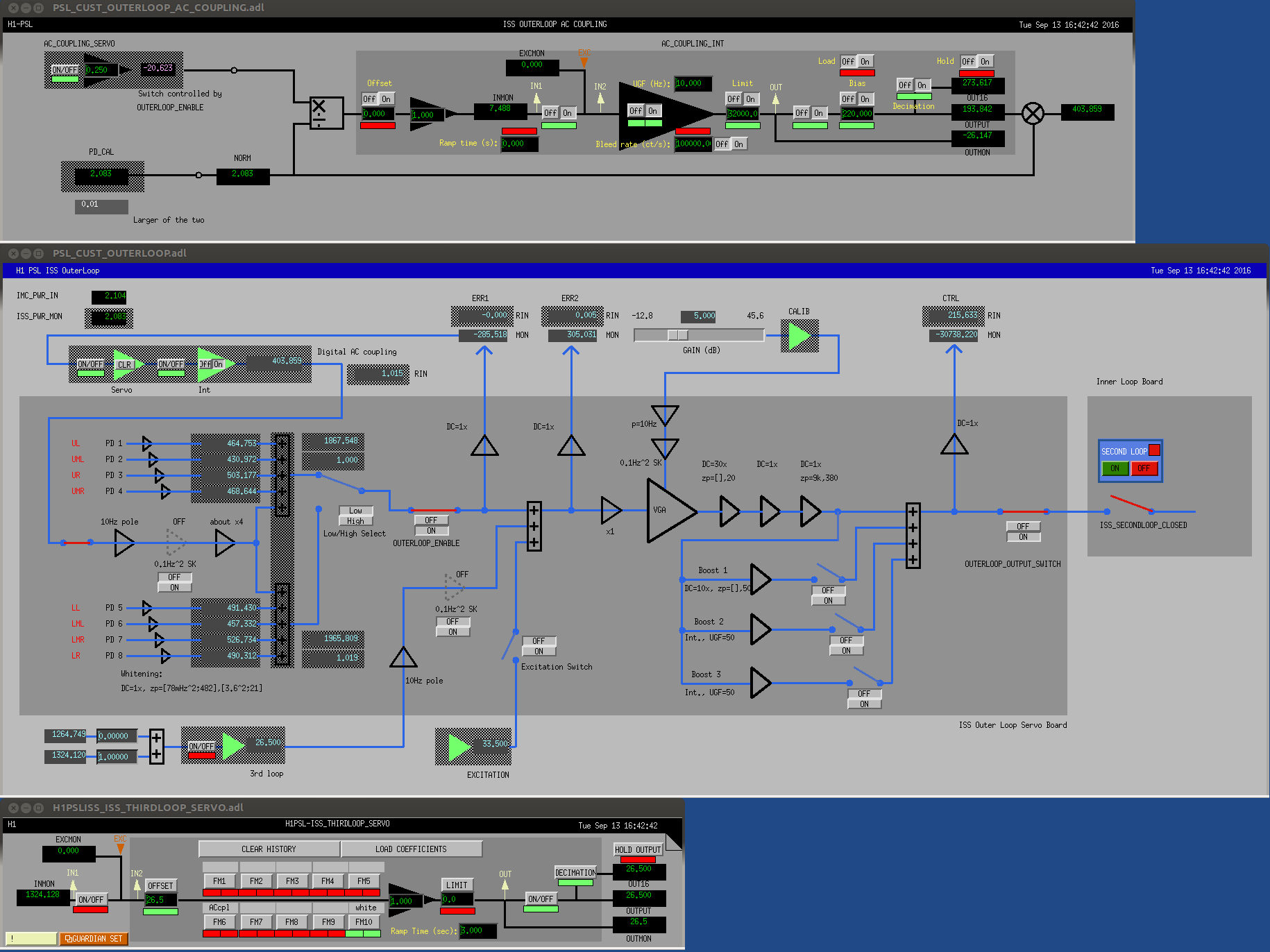
- PWR_NORM is used by the AC loop. This is not new, but we don't have to babysit it anymore (second attachment top).
- RIN of inner- and outer-loop sensors are generated by normalizing PDSUMINNER and PDSUMOUTER by PWR_NORM and an appropriate scaling constant.
Closed loop response of the AC coupling was calculated and a filter that mimics its behavior was put in FM6 of the third loop ("ACcpl") (second attachment bottom). Together with FM10 ("white") which mimics the analog whitening of the outer loop error point (which is basically zp=(78mHz^2,3.6^2)), this will make the outer loop transparent when viewed from the 3rd loop.
Images attached to this report