PMC has three transmissive output ports: EOM monitor and 2nd loop out of loop sensor are on the same main port downstream of EOM, 1st loop out of loop sensor is on another port, FSS refcav transmission monitor is on yet another port. We looked at these four sensors.
Note that this is not a conclusive entry.
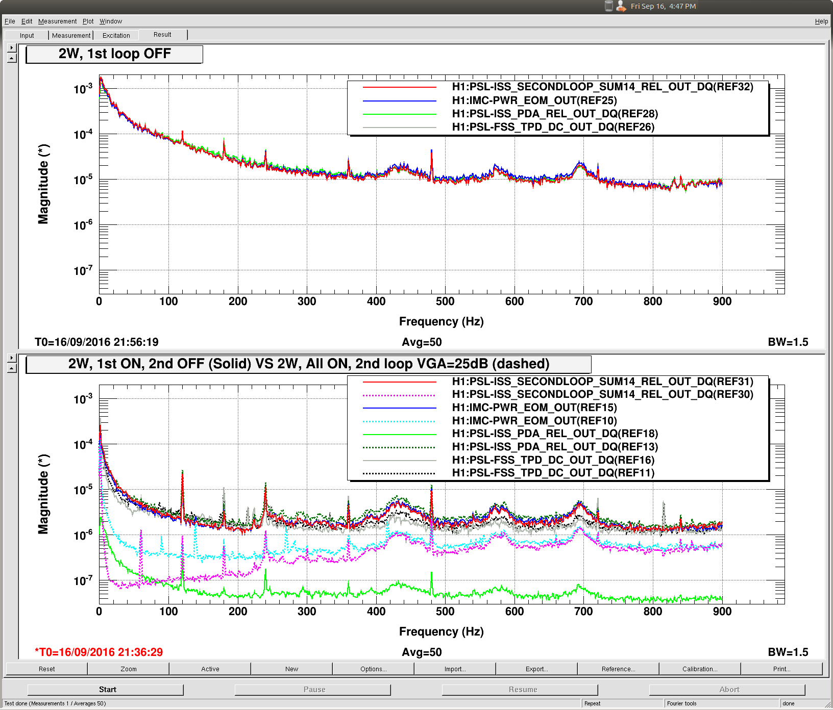
Free running RIN shows all the acoustic features and all sensors agree.
Reduction of power on ISS 1st loop sensors allowed us to look at the free running intensity noise without ISS without saturation, which was impossible before. (Actually 1st loop sensors still saturate once in a while when ISS is off, but not all the time any more.)
In the attached plot of RIN, top panel is without ISS. All sensors agree with each other including acoustic structures (I'm talking about broad bumps at around 440Hz, 580 and 680Hz).
This means that, when free-running, intensity noise coming out of PMC caused by acoustics (jitter-intensity conversion by PMC, maybe some clipping upstream, intensity noise straight out of HPO, everything combined together) is far larger than the acoustic coupling downstream of PMC. But that free-running intensity noise caused by acoustics is reduced to almost nothing with ISS, and as soon as the ISS is turned on we start looking at the residual noise caused by the jitter coupling downstream of the PMC.
We should look at DBB measurements from the past to see if the measured jitter and intensity noise out of HPO are consistent with the above picture.
ISS ON, some differences show up.
On the bottom panel (with the same Y axis scale as the top) is the same set of RIN signals with the first loop on but the second loop off (solid) and with both loops on (broken).
Roughly speaking,
- EOM monitor and the second loop sensor behaves the same way.
-
FSS sensor is squashed a factor of 2 more by the 1st loop than the second loop sensor, but doesn't change much by the 2nd loop.
- (Actually FSS sensor somewhat increases by the 2nd loop.)
-
When 2nd loop is turned ON, the 1st loop sensor becomes about the same as the 2nd loop sensor was when only the 1st loop was on.
- (Actually it becomes somewhat worse than the 2nd loop sensor was.)
Let's define jitter coupling Cn (n=1, 2, E, F for 1st loop, 2nd loop, EOM and FSS sensor) as the sensitivity of a specific sensor to the jitter coming out of PMC. Jitter generated by downstream of PMC (e.g mirror shaking) could also be included in Cn assuming that the new jitter is coherent with the original jitter.
From a simple model that is shown later, we can say that one of EQ1 and EQ2 below is true, and EQ3 is always true:
- EQ1: C2~CE
- EQ2: |C2|<<|C1|, |CE|<<|C1|
- EQ3: CF~(C1+C2)/2
What we learn.
If EQ1 is true:
There's a common coupling point upstream of EOM monitor and downstream of PMC (e.g. EOM aperture, steering mirrors, PMC enclosure window, back of the PMC mirror).
Local jitter-to-intensity coupling for each of the sensors, e.g. peri mirror causing additional jitter and IMC (with alignment offset) converting it to intensity for the 2nd loop, is much smaller than the common coupling because there's no difference between CE and C2.
We cannot say if C1 is large or small in this case except that |C2-C1| is large.
If EQ2 is true:
Jitter coupling of the first loop sensor path is the large one here (e.g. steering mirrors, PMC output window, back side of the PMC mirror, PD surface).
The EOM and the second loop sensor path jitter coupling is negligible at this level.
EQ3 is always true:
FSS path jitter coupling via REFCAV, AOM etc. happens to be about half of the first and the second loop sensor path added together.
What we should do.
ISS doesn't do anything to the jitter itself. Even if ISS is totally insensitive to the jitter, the jitter still pollutes the IFO. We need to make ISS as insensitive to the jitter as possible, but we also need to mitigate the jitter.
-
See if EQ1. is true, and mitigate.
- EOM alignment, dust particulate on the PMC enclosure window, back of the PMC mirror, and steering mirrors.
-
See if EQ2 is true, and mitigate.
- Dust particulate on the PMC enclosure window, back of the PMC mirror, steering mirrors and BS.
-
Reduce jitter. It's clear that there's too much jitter.
- Flow rate?
If jitter cannot be mitigated, and if the IFO jitter coupling as well as the IFO intensity coupling are both stable, we might be able to sense the jitter (e.g. IM4) and feed forward to ISS. Feeding back to input pointing into IMC by PZT mirror doesn't sound like a good strategy when we need to do it in wide band between 300Hz and 1kHz.
Simplest model.
Jitter coupling Cn for the sensor n (n=1 for 1st loop, 2 for the 2nd loop, E for EOM Mon and F for FSS Trans) represents all physical processes that affect the conversion of the jitter coming out of PMC into the sensor signal, e.g. clipping, misalignment of the cavity, attenuation of the HOM by cavity transmission, inhomogeneity in QE on the PD surface etc.
When the 1st loop is ON but the second loop is OFF
The error signal for the sensor n (n=2, E and F) becomes this:
- En(1)=Cn-C1
where the number 1 in En(1) means that the 1st loop is closed but the 2nd is open.
Solid traces in the bottom plot represent |En(1)|.
When both of the loops are ON:
- d=1/(1+G) where G is OLTf of the 2nd loop
- E2(2)=d(C2-C1)
- E1(2)=(d-1)(C2-C1)=-G/(1+G) * E2(1)
- EE(2)=d(C2-C1) - C2 + CE
- EF(2)=d(C2-C1) -C2 +CF.
Dashed traces represent |En(2)|.
Looking at measured quantities.
The second loop sensor (red solid and pink dashed) and the EOM monitor (blue solid and cyan dashed) behave the same way, i.e. |E2(1)|=|EE(1)| and |E2(2)|=|EE(2)|, thus
- |C2-C1|=|CE-C1|
- |d(C2-C1)|=|d(C2-C1)-C2+CE|
These equations hold true despite the fact that EOM mon is upstream of IMC while the second loop sensor is downstream.
One of the below should be true:
- C2=CE, they are not small but they originate from somewhere upstream of the EOM monitor (but downstream of the PMC by definition).
- |C2|<<|C1|, |CE|<<|C1|.
Also, when the 1st loop is on but the 2nd loop is off, the FSS monitor (gray solid) is about half of the second loop sensor (red solid), i.e. |EF(1)|=|E2(1)|/2, thus:
-
|CF-C1| = |C2-C1|/2, i.e.
- CF-C1=(C2-C1)/2,
- or CF-C1=-(C2-C1)/2.
One of the above is eliminated if you look at EF(2) (black dashed):
- EF(2) = d(C2-C1)-C2+CF = [d(C2-C1)-(C2-C1)]+(CF-C1) = E1(2)+EF(1)
i.e. black dashed should be the sum of dark green dashed and gray solid. Green dashed E1(2) is mostly out of phase with C2-C1 because |d|<1. Since black dashed EF(2) is a factor of 2 smaller than dark green dashed, the only explanation is that gray solid EF(1) is out of phase with E1(2) and in-phase with C2-C1, thus
- CF-C1=(C2-C1)/2, i.e. CF=(C2+C1)/2.
This is as far as we can get with this simple thing, I think.