Attached is the OLTF in two configurations with 7dB VGA gain.
50W (actually 48W), AC coupling OFF, and boost ON (solid line)
50W (actually 48W), AC coupling ON, boost OFF (dashed).
UGF is about 9kHz with phase margin of 40 deg or so (boost ON) or 50 (boost OFF).
Boost buys us about 9dB more gain at 1kHz.
I asked Kiwamu to do an analog measurement up to higher frequency on the floor.
Here is a transfer fucntion with SR785 to check the high frequency portion.
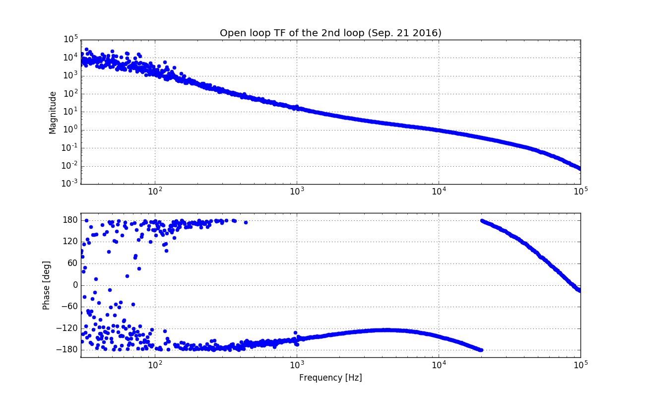
Also, the attached zip contains the data, plot script, and figure.

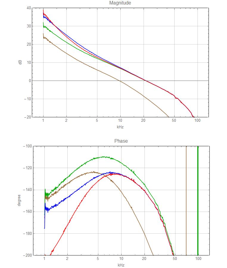
Taking this data I looked at modifications to the ISS board to increase its bandwidth. The attached plot shows:
- brown — original measurement
- green — adding a zero at 20kHz and adding a gain of 2
- blue — same as green but also moving the knee of the boost from 2kHz to 4kHz
- red —same as green but adding a second boost with knee at 2kHz.
Adding the 20kHz zero is a no brainer, since it only requires to limit the dominant pole in the circuit. It improves the phase margin over the measured curve and allows the ugf up to move to 20kHz. This will increase the ISS gain by 2 at 1kHz. The increased ugf and phase margin will in turn allow us to move the knee of the boost higher with the option to add a second boost. The later two solutions will add another gain of 2 at 1kHz.
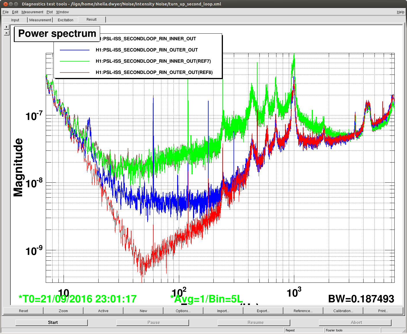
We engage the ISS boost twice today in low noise, and did not see any impact on the DARM noise. We expected an improvement at 1 kHz at least. Attached are before and after spectra of the in and out of loop diodes (at least that's what I think the new cahnnel names mean). If it is correct that INNER means in loop and outer means out of loop, we are sensor noise limited at 100 Hz with the boost on.