ISS has true in-loop signal called H1:PSL-ISS_SECONDLOOP_RIN_ERR1 that is picked off of the error point of the second loop board, and we also have pseudo in-loop and out-of-loop sensor called RIN_INNER and RIN_OUTER that are digital sum of indivisual PD output.
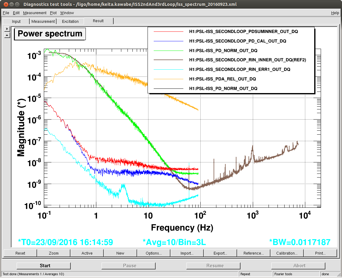
In the morning we noticed that pseudo in-loop and out-of-loop sensors have huge low frequency noise (first attachment, brown).
Three problems were identified:
- The scaling operation to make RIN somehow involved dividing by 1st loop sensor DC though this is unnecessary. This 1st loop sensor is green on the same plot and perfectly agreed with brown.
- The digital SUM of individual diodes seemed to be limited by the single precision math (red, blue). This is because individual PD output has large DC.
- Somehow it seemed as if the pseudo in-loop signal was larger than out-of-loop and it seemed as if in- and out-of-loop was swapped.
The first problem will be solved by model change, but for now we disabled the scaling.
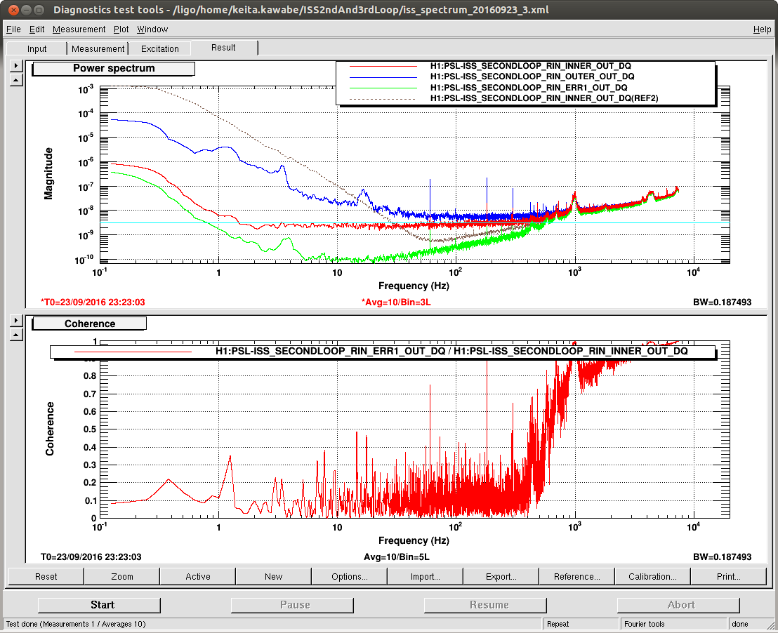
The second problem was solved by adding HPF in the RIN_INNER and RIN_OUTER.
After these, huge noise was gone, and now the RIN_INNER became smaller than RIN_OUTER, but the discrepancy between the RIN_INNER and the true in-loop signal didn't make sense (second attachment).
We went to the floor and disconnected the PD5-8 cable from the front panel of the chassis, and confirmed that all PD 5-8 signals went away, and got confident that INNER- and OUTER- are NOT swapped anywhere.
However, when I connected the cable back, PD5 signal had a huge offset, and the DC channel and the whitened channel were opposite in sign, which doesn't make sense. It seems like something happened on the transimpedance board.
We turned the power of the chassis off, disconnected the PD5-8 cable, and powered it on again, and the PD5 DC channel has a huge offset.
We did NOT put PD5-8 cable on PD1-4 connector as we feared to break PD1-4 channels.
The chassis will be pulled for investigation on Tuesday.