
REMOVE SEARCH FILTER
SEARCH AGAIN
Search criteria
Section: H2
Task: SEI
TITLE: 08/19 Day Shift: 1430-2330 UTC (0730-1630 PST), all times posted in UTC
STATE of H1: Planned Engineering
OUTGOING OPERATOR: None
CURRENT ENVIRONMENT:
SEI_ENV state: CALM
Wind: 4mph Gusts, 1mph 3min avg
Primary useism: 0.01 μm/s
Secondary useism: 0.07 μm/s
QUICK SUMMARY: Dust alarms in the PSL overnight, but they quickly dissapated. There was a verbal alarm at 0828UTC "Check corner station HEPI pumps", I don't initially see any issues but I'll continue to investigate.
Plan today is continued corner station commissioning unless we get the arms opened.
TITLE: 08/13 Day Shift: 1430-2330 UTC (0730-1630 PST), all times posted in UTC
STATE of H1: Planned Engineering
OUTGOING OPERATOR: None
CURRENT ENVIRONMENT:
SEI_ENV state: CALM
Wind: 5mph Gusts, 3mph 3min avg
Primary useism: 0.01 μm/s
Secondary useism: 0.08 μm/s
QUICK SUMMARY:
HAM7 will be a focus today with quick SQZ backscatter measurements (Rahul gave the thumbs up for SUS yesterday) and then longer SEI suite of health checks by Jim before potential close-out for sealing up HAM7 (which means lots of activities in the East Bay with Forklift/crane/other noisy activities).
IFO work with continue with Masayuki. CRS work continues.
On the Reservation System, I don't see "LVEA Local" laser Hazard, but yesterday we had local laser hazard for HAM7.
Smoky day continue (although you can faintly see Rattlesnake). This morning has shown a slow trend down in AQI to 148 (orange) from a peak of 165(red) overnight...yesterday at 10am we were at 11AQI (green).
Checking on Laser Status
The entire LVEA is currently laser SAFE.
At LVEA East Bay, the panels on the SOUTH side were cleared out of the way. And on the NORTH side they were still up (with a little walkway entrance OPEN) and there was a Laser SAFE sign posted.
So, at the moment the ENTIRE LVEA is SAFE. Just wanted to assess things this morning with all the acitivities.
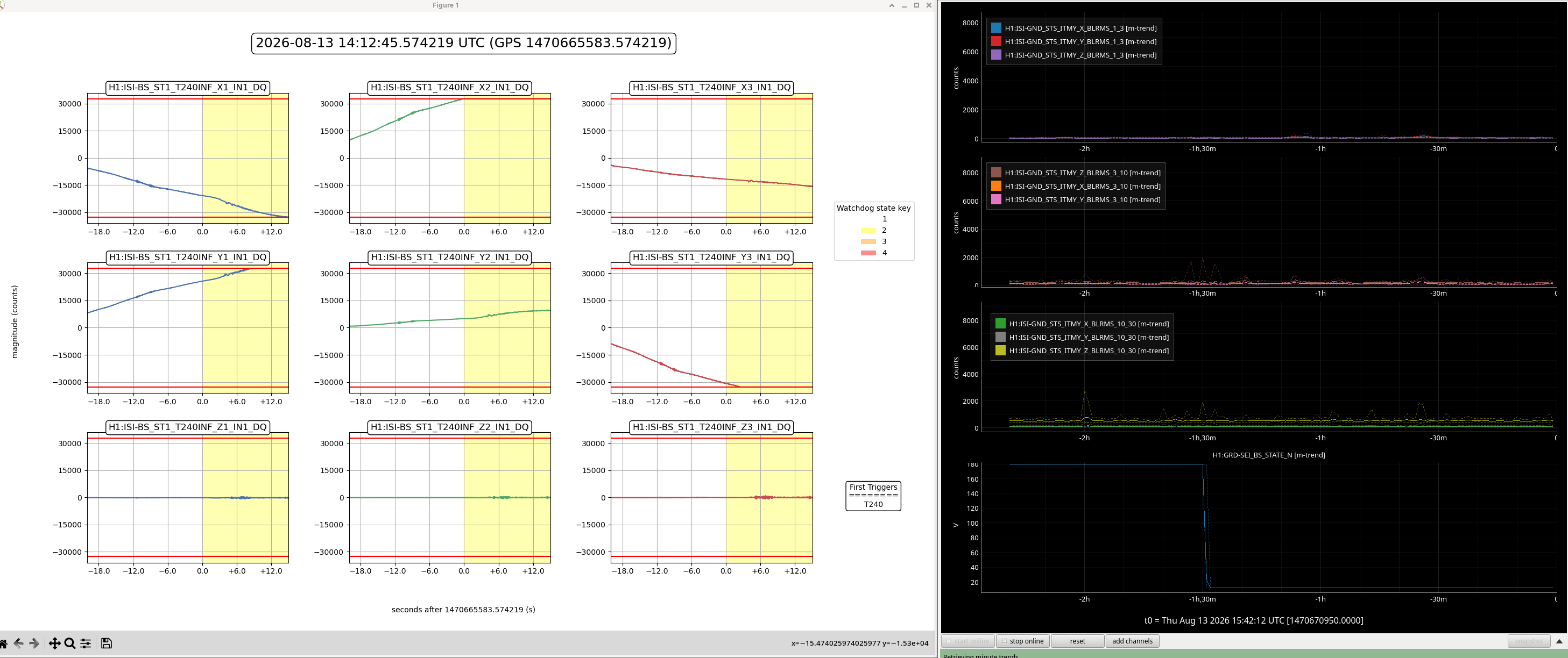
We untripped the SEI_BS Watchdog, it had a T240 trip at 7:12am PT (14:12 UITC), see attached. We untripped the watchdog with no issues.
Wanda V., Reinhardt R.

On Friday (08/07) we connected both fibres which measure the arms to the Febus interrogator, with the X arm on Ch1 and the Y arm on Ch2. This frees up the Sintela interrogator for Reinhardts experiments.

The Febus interrogator is now measuring at 2500 Hz with a downsample factor of 10 before saving, coming to a recorded sampling rate of 250 Hz. The gauge length was 6m. In case there is a crash or the measurement needs to be restarted, the pipleline to load is LIGO_20260807_DS_SR_Writer_both250hz_v2. Filesize is ca 50 MB/min/channel

Monday August 10th:
We measured at 10 m gaugelength over the weekend and it was changed to 6m at 11:00 am (PST) on Monday.

The filesize is roughly 100 MB/min for the 6m gaugelength (so 200 MB/min for both channels) and roughly 60 MB/min per channel for 10m GL. If this measurement should be restarted, the pipeline is LIGO_20260807_DS_SR_Writer_both250hz_v3.

In principle, the interrogator can now run "as is" through IR1, but we are still free to change any of the settings.
TITLE: 08/10 Day Shift: 1430-2330 UTC (0730-1630 PST), all times posted in UTC
STATE of H1: Planned Engineering
OUTGOING OPERATOR: None
CURRENT ENVIRONMENT:
SEI_ENV state: EARTHQUAKE
Wind: 7mph Gusts, 4mph 3min avg
Primary useism: 0.58 μm/s
Secondary useism: 0.09 μm/s
QUICK SUMMARY:
NOTE: Both Ops work stations had troubles logging in (I could enter my username, but then the computer would freeze...for both computers). So I'm back here at cdsws27. It worked, but it was a little slow.
We had a M7.4 earthquake in Bogota (sort of in between Cali/Medellin/Bogota) that rolled in here about 2hrs ago. Looks like this has mainly tripped mostly LVEA HAMs. Picket Fence is lighting up in yellow also.
Oh and Rattlesnake Mountain finally returns (after missing quite a bit last week due to a smoky week). AQI for Richland (closest sensor on AirNow) is at a YELLOW 71. Only active fire in Benton Franklin counties is far away up near Kahlotus (Nunamaker Road Fire with 20k+ acres.
Also, the GWANW (Gravitational Wave Astronomy North West) meeting will be hosted here at LHO today and tomorrow.
Post NOTE: Looks like BOTH ops workstations have now moved to the password for the login, so I will try to move back there.
Untripped HAMs 1-5+8 After the Colombia EQ tripped them at 1245utc (545amPDT).
Whoops...apparently I did NOT un-trip HAM8 ISI. But that's ok since SEI group is working on CPS for HAM8 this morning.
TITLE: 07/30 Eve Shift: 2330-0500 UTC (1630-2200 PST), all times posted in UTC
STATE of H1: Planned Engineering
OUTGOING OPERATOR: Oli
CURRENT ENVIRONMENT:
SEI_ENV state: CALM
Wind: 15mph Gusts, 9mph 3min avg
Primary useism: 0.04 μm/s
Secondary useism: 0.09 μm/s
QUICK SUMMARY:
Not much going on today as the CDS team was working on the file system today.
Revived BS's Hepi and ISI. Lets see if it's more stable now.
TITLE: 07/29 Eve Shift: 2330-0500 UTC (1630-2200 PST), all times posted in UTC
STATE of H1: Planned Engineering
OUTGOING OPERATOR: Oli
CURRENT ENVIRONMENT:
SEI_ENV state: MAINTENANCE
Wind: 10mph Gusts, 5mph 3min avg
Primary useism: 0.71 μm/s
Secondary useism: 0.12 μm/s
QUICK SUMMARY:
Dan, Jonathan, & Erik are still working on the file server. OPS-Overview is still all red.
But Jonathan just walked in and said I can start recovering the IFO.
So i will start taking the SEI and the SUS back to Damped and aligned.
PSL team said that they have relockedthe PMC and i may drift in the next 24 hours.
The HEPI, ISI, and Optics have been recovered.
All SEI Guardians for all chambers has been set to ISI Damped HEPI Offline , Except HAM7 and BS. BS ISI watchdogs are tripping for some reason.
All Optics are set to Aligned.
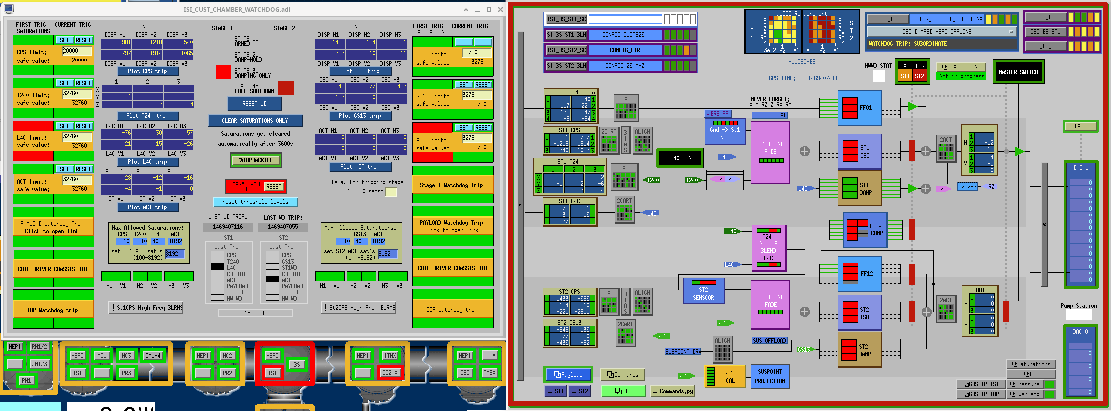
Misaligned MC2, PRM, and SRM
J. Kissel

Seeing the "first light," calibrated SPI Optical Lever amplitude spectral densities in  and , and thinking about ADC noise limitations and the calibration models assumption that the spots are centered on the QPDs drove me to re-check the spot positions on the QPDs.

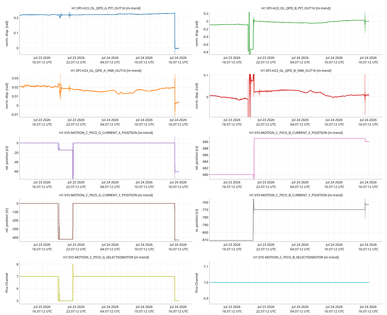
Timeline of centering:
    2026-07-17 17:00 UTC (LHO:91124) -- Jennie turned on the SPI laser for the first time since doors went on and the ISIs were isolated, and re-centered *only* QPDB with M_C1 (and thought she had adjusted QPDA centering with M_M1, thought she had mistakenly moved M_M2, but confirmed later she did not; LHO:91219).
    2026-07-23 14:00 UTC (LHO:91218) -- Jim unlocks and restores function of HAM2 HEPI, such that now both HAM2 and HAM3 are fully functional, and remain ISOLATED with corner station sensor correction ON as their nominal condition.
    2026-07-23 20:30 UTC (LHO:91221) -- Jennie re-centered (only) QPDB again using M_C1.
    2026-07-24 16:05 UTC (this aLOG) -- Not knowing that Jennie had yet recentered any QPDs, and finding QPDA PIT's normalized beam displacement at +0.23 [rad], I recentered *both* QPDA and QPDB.

I attach a similar trend of relevant channels including both Jennie's centering work from 2026-07-23 and mine this morning. Similar to Jennie's plots but with thick lines, light mode, and with the y-axes labeled.
I saved this template to
    /opt/rtcds/userapps/release/spi/h1/ndscope/QPD_Centering.yaml  (rev 35598).


Here're the DC values of the QPDs after this morning's centering (done with the precision one can achieve with a picomotor STEP SIZE of 1 [ct]):
$ gpstime now;z avg -30 H1:SPI-H23_OL_QPD_A_PIT_OUT_DQ H1:SPI-H23_OL_QPD_A_YAW_OUT_DQ H1:SPI-H23_OL_QPD_B_PIT_OUT_DQ H1:SPI-H23_OL_QPD_B_YAW_OUT_DQ -s

t =
PDT: 2026-07-24 09:27:44.113664 PDT
UTC: 2026-07-24 16:27:44.113664 UTC
GPS: 1468945682.113664

Channel                        t-30 sec average       t-30 standard deviation
H1:SPI-H23_OL_QPD_A_PIT_OUT_DQ -0.0024822048842906954 4.722167842008142e-06
H1:SPI-H23_OL_QPD_A_YAW_OUT_DQ  0.0030039884615689514 5.884913671432033e-06
H1:SPI-H23_OL_QPD_B_PIT_OUT_DQ -0.0022898733150213957 8.094109742945136e-05
H1:SPI-H23_OL_QPD_B_YAW_OUT_DQ  0.008859152471025783  4.6337990240392655e-05

$ gpstime now;z avg -30 -s H1:SPI-H23_OL_QPD_A_PIT_OUT_DQ H1:SPI-H23_OL_QPD_A_YAW_OUT_DQ H1:SPI-H23_OL_QPD_B_PIT_OUT_DQ H1:SPI-H23_OL_QPD_B_YAW_OUT_DQ H1:SPI-H23_OL_QPD_A_SUM_OUT16 H1:SPI-H23_OL_QPD_B_SUM_OUT16

t0 =
PDT: 2026-07-24 09:54:54.983607 PDT
UTC: 2026-07-24 16:54:54.983607 UTC
GPS: 1468947312.983607

Channel                        (t0-30 sec) average       (t0-30 sec) standard deviation
H1:SPI-H23_OL_QPD_A_PIT_OUT_DQ  -0.002713  3.4e-05
H1:SPI-H23_OL_QPD_A_YAW_OUT_DQ   0.003265  4.2e-05
H1:SPI-H23_OL_QPD_B_PIT_OUT_DQ  -0.002033 10.0e-05
H1:SPI-H23_OL_QPD_B_YAW_OUT_DQ   0.009682 5.3e-05
H1:SPI-H23_OL_QPD_A_SUM_OUT16   25.846691 0.003820814636259141
H1:SPI-H23_OL_QPD_B_SUM_OUT16   29.265472 0.004081774857250754
J. Kissel

As it stands now, QPDA on ISI HAM2's ISIJ reflector is measuring the rotation of the ISI HAM3. The channels H1:SPI-H23_OL_QPD_A_{PIT,YAW}_OUT_DQ are still in "normalized position of the beam, s" [V/V = "radians"], as SEG1, SEG2, SEG3, and SEG4 have been converted from ADC counts to ADC volts with the transimpedance whitening stage compensated (see LHO:91157), and the PIT (lower - upper) and YAW (left - right) in [V] are divided by the SUM in [V].

Executive Summary:

Modeling the PITCH calibration of QPDA's normalized spot position, s, into ISIHAM3 rotation angular displacement, \alpha, yields 209.6e-6 [rad/rad], excellently similar to Arnaud's measured 240e-6 [rad/rad] from 91194.

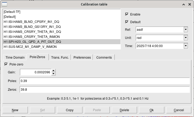
Thanks to Arnaud's excellent sharing/bookkeeping, I opened his template, and updated the calibration and post the plot again here. I also attach the updated calibration window parameters for the SPI channel, in the updated template which has been committed to
    /ligo/svncommon/SeiSVN/seismic/HAM-ISI/H1/HAM3/CRS/Templates/dtt/2026-07-18_0600UTC_H1ISIHAM3_CRSvsSPIvsISI_PIT_ASD.xml
(Note to future users, the QPD's whitening compensation is *included* in the calibration of this template because 2026-07-18 06:00UTC was before I turned on the front-end compensation for it on 2026-07-23 LHO:91157. So if you measure the ISI *after* 2026-07-23, then you don't need the (z:p) = (39.8:0.039) [Hz] zero-pole compensation in the DTT calibration. Also beware - after this aLOG I'm going to install the [rad/rad] calibration into the front-end too.)

This doesn't change the answer much (see updated plot below): the H1SPIH23 optical lever measure of ISI HAM3 PITCH is dominated by ADC noise up the 1-10 Hz region, as (sadly) expected from the SPI final design; see Figure Figure 1biii.2 of T2400145. This is because the beam spot is so large at HAM2 QPDA, and *that's* because we didn't have room on the HAM3 ISIK transceiver to include a beam reducing telescope that would decrease the spot size at ~15.5 [m] away.

The model, math, and calculation:

Sign conventions -- assume QPDA "+x" is -Y IFO coordinates and +YAW = +RZ of ISIHAM3, and QPDA "+y" is + Z IFO coordinates, and +PIT = +RY of ISIHAM3.

Thru integrating the power of the Gaussian beam at the QPD, P_y(x,y), from -infinity (the -y, i.e. -Z edge of the QPD) to the top / bottom (i.e. that between S1+S2 and S3+S4) boundary, one gets

                       / +inf   / y        2 P_{0}       w_{0}^{2}        2 (x^{2} + y^{2})
    P_y^{lower}(x,y) = |        |       --------------   ---------  exp( ------------------ ) dx dy
                       / -inf   / -inf   pi w_{0}^{2}      w^{2}                w^{2}

                              pi      2 P_{0}    / y               y^2
                     = sqrt( ---- )  ----------  |       exp( - 2 -----) dy
                               2      pi w^{2}   / -inf            w^2

                         P_{0}                     y
    P_y^{lower}(x,y) =   ----- (1 + erf ( sqrt(2) --- ) )
                           2                       w

with y being the spot position of the beam, with power, P_{0}, and radius, w, at the detector. erf is the well-defined Gaussian Error Function. Assuming the beam is centered on the QPD, that means the power on the top and bottom halves are equal, and thus s_pit as
              P_y^{lower} - P_y^{upper}
    s_{pit} = ---------------------
                       P_{0}

                          y
    s_{pit} = erf( sqrt(2) ---  )
                          w

                 erf(z) ~ 2 z / sqrt(pi)

              2 sqrt(2)  y
    s_{pit} = --------  ---
              sqrt(pi)   w

Importantly, s is a dimensionless quantity. Regardless of whether the QPD segments are (a) uncalibrated, (b) calibrated into ADC volts proportional to photocurrent, or (b) calibrated into milliWatts of incident power, if you create a creating PIT and YAW signal, that's normalized by the SUM in the same units, then you *always* gets you the "right" normalized spot position units. Some folks are even so bold as to refer to the QPDs as "self-calibrating" because of this.

But there's more to calibrating the QPD if you want to interpret the normalized spot position as an angle from somewhere. We do so by first solving for the spot displacement at the QPD, y, (converting 2 sqrt(2) = sqrt(8) along the way)

              pi
    y = sqrt( --- )  w  s_{pit}
               8

and then assume a very scalene right-triangle and the small-angle approximation convert the beam displacement to +\theta_PIT = +RY in [radians]. That process ends with "just" dividing by the "lever arm," L_{OL} distance between the HAM3 ISI center of rotation and the QPDA's curve mirror on the +X face of the HAM2 ISI,

                      y           1            pi
    \theta_{PIT} =  -----   =   -----   sqrt( --- )  w  s_{pit}
                    L_{OL}      L_{OL}         8

One can run through the same math to get the similar answer for \theta_{YAW), if one assumes no astigmatism in the beam:

                      x           1            pi
    \theta_{YAW} =  -----   =   -----   sqrt( --- )  w  s_{yaw}
                    L_{OL}      L_{OL}         8


So generically, we can compute one number to calibrate normalized spot position at the QPD in [radians] into displacement angle of the ISI from which the lever beam was launched in [radians]:

    \alpha_{PIT,YAW}                          pi      w
    ---------------- =  \kappa_{OL}  =  sqrt( --- ) -----
       s_{pit,yaw}                             8    L_{OL}


So, let's compute this number for the QPDA system.

From T2400304, the centers of rotation to the opposing side wall distance is 15.4274 [m]. Subtracting a the little bit of length of the ISIJ reflector 0.12 [m] for HAM2 for completeness, that's

    L_{OL} = 15.4274 - 0.12 [m] = 15.3074 [m],

Using the measured beam waists from LHO:89181, assuming no astigmatism for now and this the waist radius is w_{0} = 1.034e-3 [m] (and thus an uniform "type B" error bar of +/- 0.005e-3 [m]), the beam radius of the meas beam propagated to 15.3074 [m],

    w(z = 15.3074 [m]) = 5.119e-3 [m] +/- 0.02e-3 [m]

    ,

Then the calibration from normalized beam spot displacement units to angle of ISI HAM3 is

                        pi     5.119e-3 [m]
    \kappa_{OL} = sqrt( --- ) ------------
                         8     15.3074 [m]

                = 2.096e-4 [m/m] or [rad/rad]
                = 209.6e-6 [rad/rad]
    \kappa_{OL}   = 209.6 [urad/rad]

This number is consistent with what Arnaud measured as 240 [urad/"ct"] with the driven transfer function in LHO:91194 (he didn't know that it's not "ct" but the normalized spot position "rad").
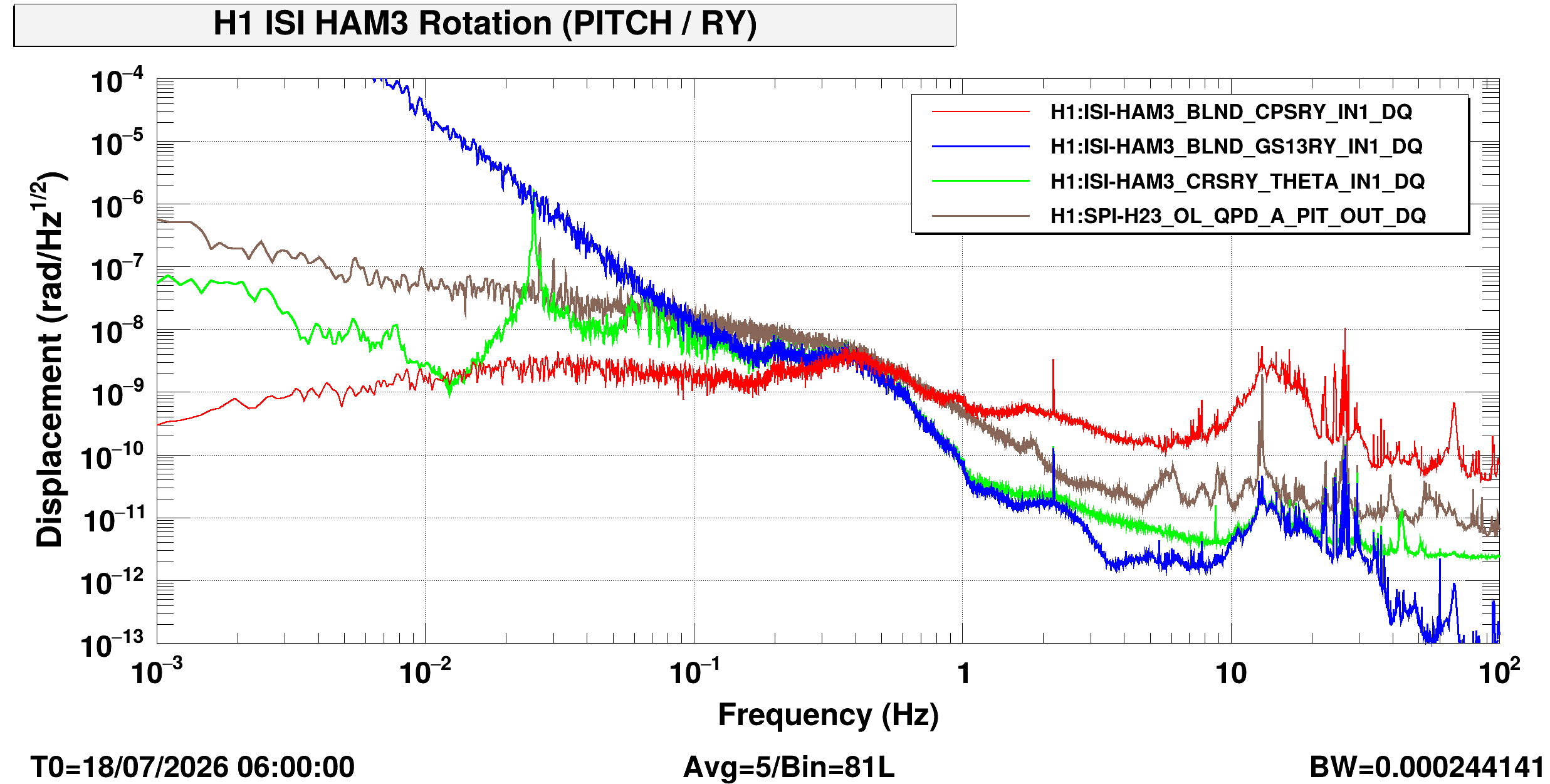
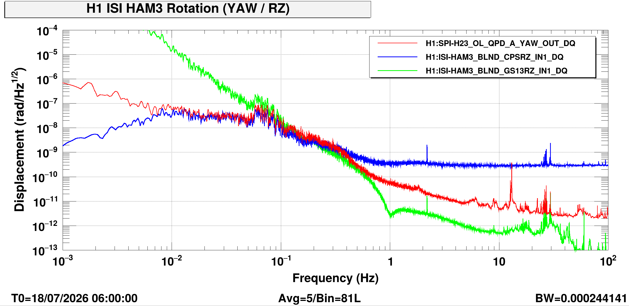
Here's the YAW ASD (sans a CRS of course), with GS13 and CPS calibrated with the same Arnaud calibration, and SPI OL YAW calibrated with the same 209.6 [urad/rad].

As expected -- more coherence than PIT, measuring real (but different) signal below ~0.5 Hz.
Compare with Figure 1biii.3 from the Final Design Doc T2400145.
The SPI ISI HAM3 OL YAW likely loses coherence below 0.01 Hz because the QPD again becomes dominated by ADC noise, because of the large spot.

WP 13447
A L4C Interface Chassis was installed in the CER rack SEI-C2, slot U10. Output signals connected to both HAM ISI Anti-Alias Interface Chassis on slots U39 and U38. Part of HAM2 L4C upgrade.
AA Chassis Slot U39: Channels 25-28
AA Chassis Slot U38: Channels 25-28 and channels 29-32
Serial Number of Chassis: S2501278
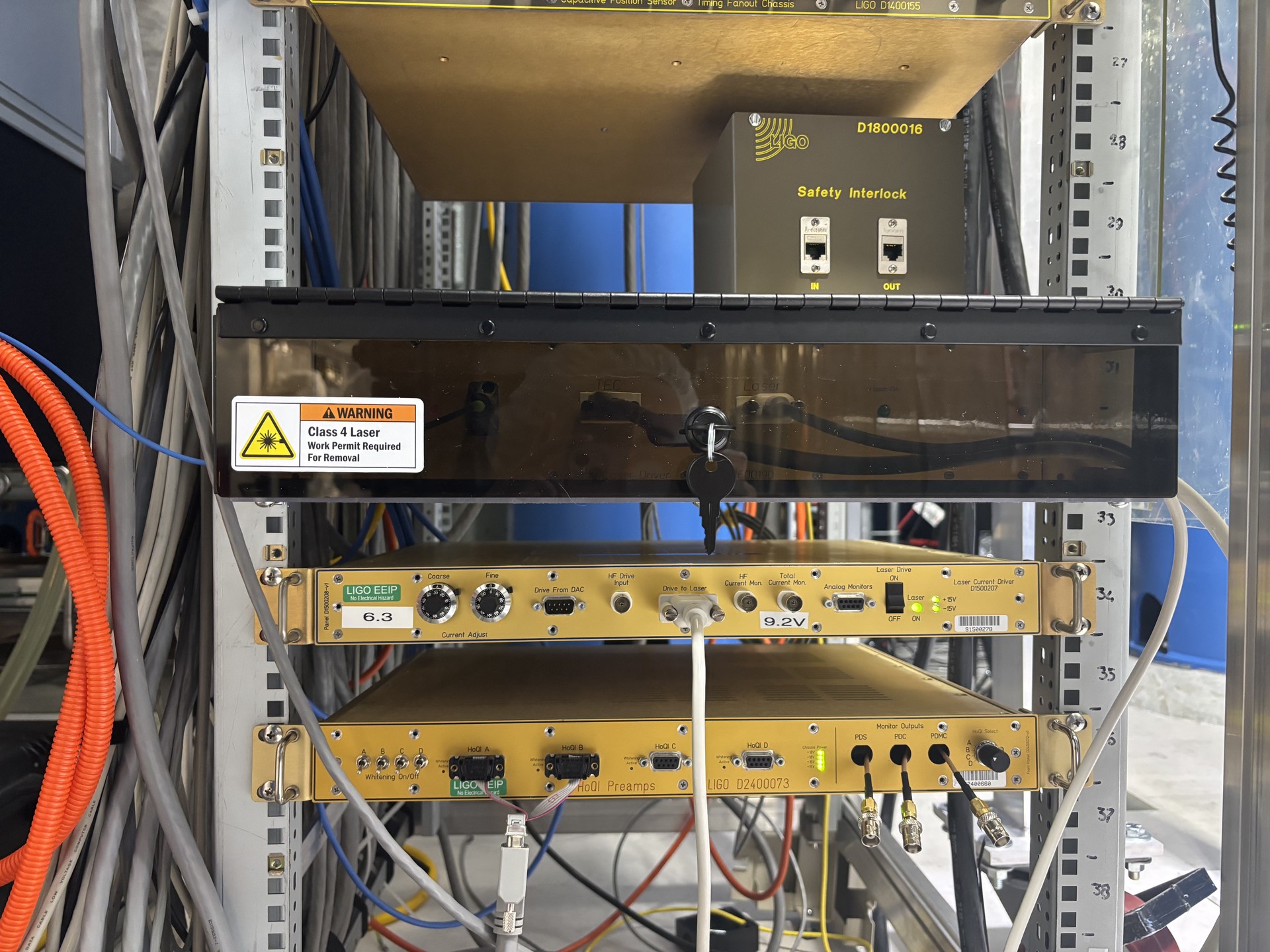
I finished hooking up everything to the new CRS laser chassis (see alog 91067 and photo attached) and turned on the laser. There will be a couple of changes to be made to the chassis (swtiching which chassis the the plexi box covers, attaching stickers etc.) but for now the CRS is up and running (minus damping). I'll continue to keep an eye on it, but until the damping is hooked up it seems unlikely that it will damp down on it's own while there's still activity in the LVEA
WP 13426
The CRS laser Chassis D2600190 was installed in rack TCS-R2. Chassis houses the CRS laser, mount, and fiber spool. A plexi security cover was installed over the chassis.
The plexi should be installed in front of the Laser Driver D1500207 rather than in front of the D2600190 chassis.
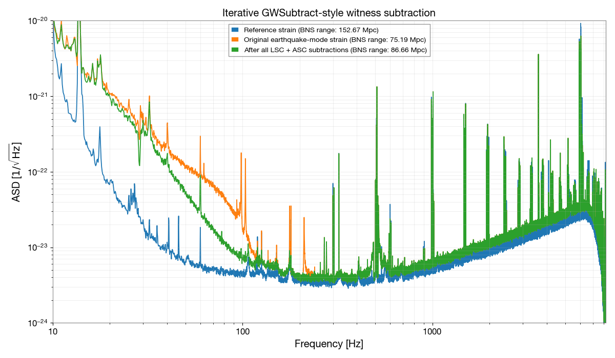
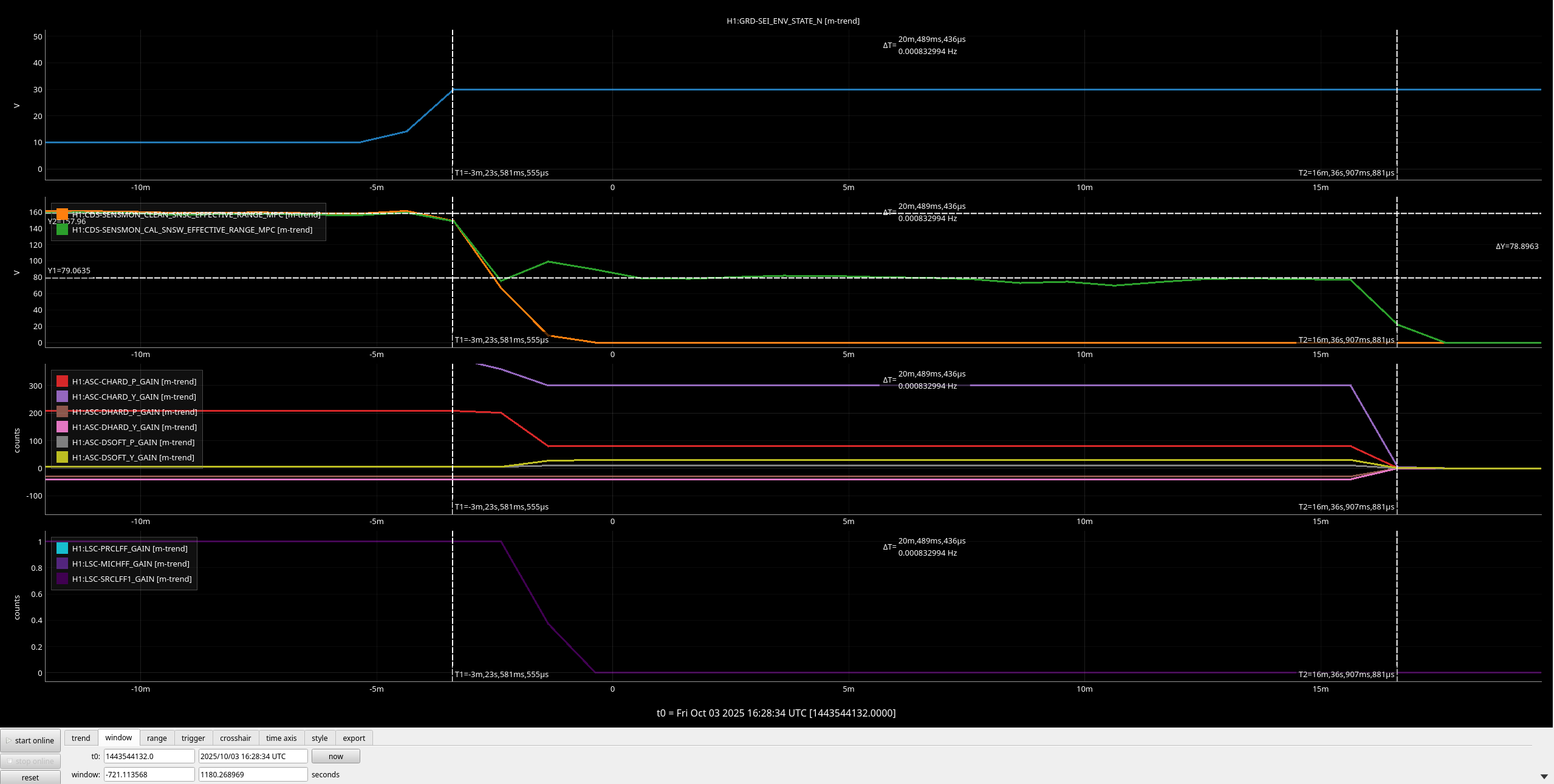
We have an earthquake mode that allows us to move into higher bandwidth interferometer controls during an Earthquake. Those controls also cause extra noise, as noted in this alog, so we are trying to subtract the injected linnear noise during this mode. Here is a trend of the seismic environment state and the sensmon range channel detector sensitivity. The plot shows that once we transitioned into earthquake mode, we were in earthquake mode for about 15 minutes before a lock loss. It is also visible that the gains are changing on the channels.
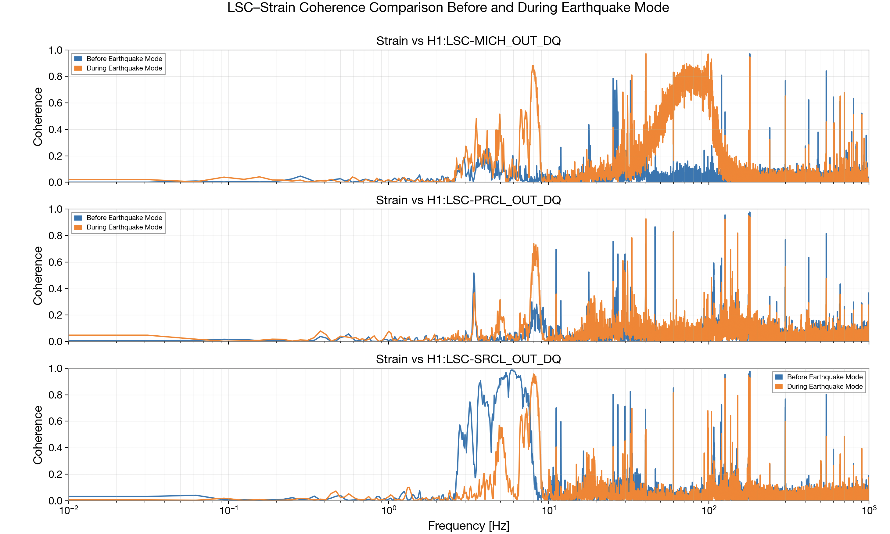
Elenna and I decided to try subtracting the noise from the interferometer controls during those 15 minutes starting at GPS 1443544132 and ending at 1443544932, see this alog for reference. I am comparing this GPS time for this earthquake to one hour before so we can know what the sensitivity should look like if we subtract all of the noise. We decided to subtract the channels whose gains changed. The channels subtracted were
H1:ASC-DHARD_P_OUT_DQ,
H1:ASC-CHARD_Y_OUT_DQ,
H1:ASC-DHARD_Y_OUT_DQ,
H1:ASC-CHARD_P_OUT_DQ,
H1:ASC-DSOFT_Y_OUT_DQ,
H1:ASC-DSOFT_P_OUT_DQ,
H1:LSC-MICH_OUT_DQ,
H1:LSC-PRCL_OUT_DQ,
H1:LSC-SRCL_OUT_DQ.
The channel with the greatest noise contribution was H1:LSC-MICH_OUT_DQ, which I determined through taking the coherence of all the LSC and ASC channels and the witness channel. The final subtraction and BNS change are visble in this GWSubtract file. Therefore, if we run a noise subtraction during earthquake mode we know we can get back at least 11 Mpc of sensitivity. This would be useful if we made a detection during earthquake mode, however we could still do better by around 70 Mpc. I plan to make this into a more usable tool and look into what is causing the rest of the noise next. I also plan to look into more channels to see if others might be causing noise as well. Since this is an earthquake mode time, it is possible the earthquake is modulating some of these channels, so a nonlinear noise subtraction may make more sense.

Jennie W
As per work permit #13412 the SPI laser has been unshuttered using the shutter controller on the floor behind the R4 electronics racks.
This is to monitor SPI alignment as the pumpdown continues and uses powers below 100 mW.
See photo showing the demodulated signals for the Rreference and Measurement SPI interferometers after the laser was unshuttered at 18:08:11 UTC.

After consulting with Jim I set the guardian to take HAM2 and 3 to isolated at 19:23 UTC. They had been damped so this will change the HAM2-3 relative alignment a bit.
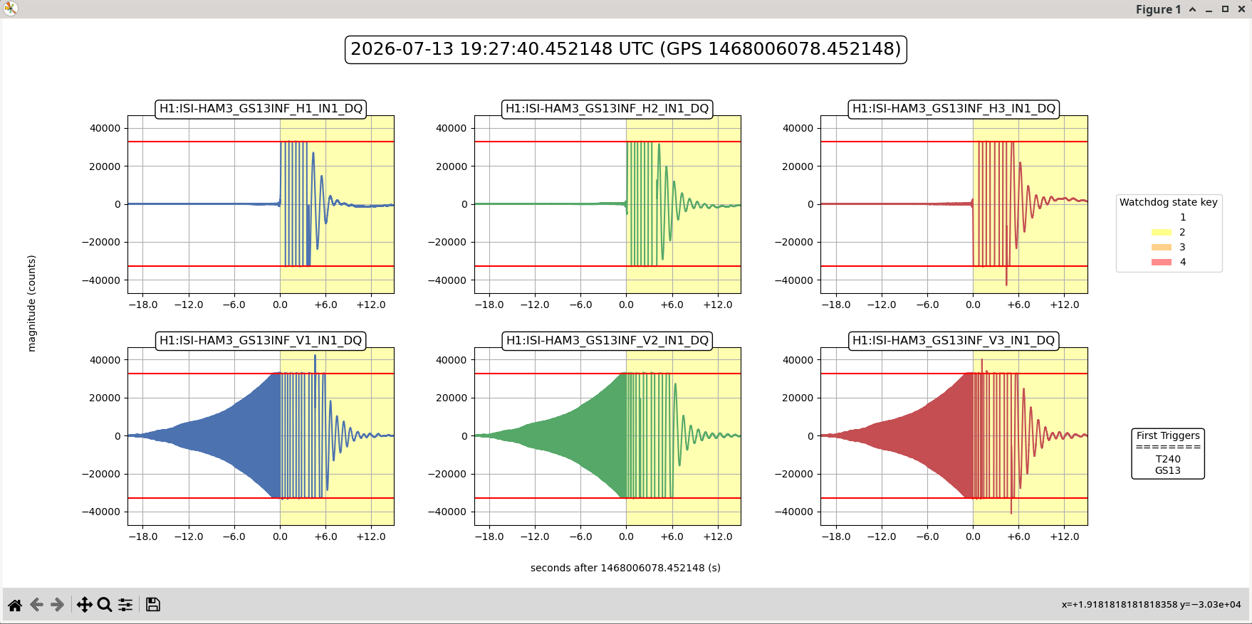
This caused HAM 3 tp trip so both ISIs have been taken to DAMPED.
Right ndscope is the QPD on HAM3, you can see the alignment changed massively when it tripped and then went back after both ISIs were taken to DAMPED.
Left ndscope shows the HAM2 QPD which doesn't have a big change between damped -> isolated -> damped.

Here is the plot for the GS13s on HAM3 as it tripped.
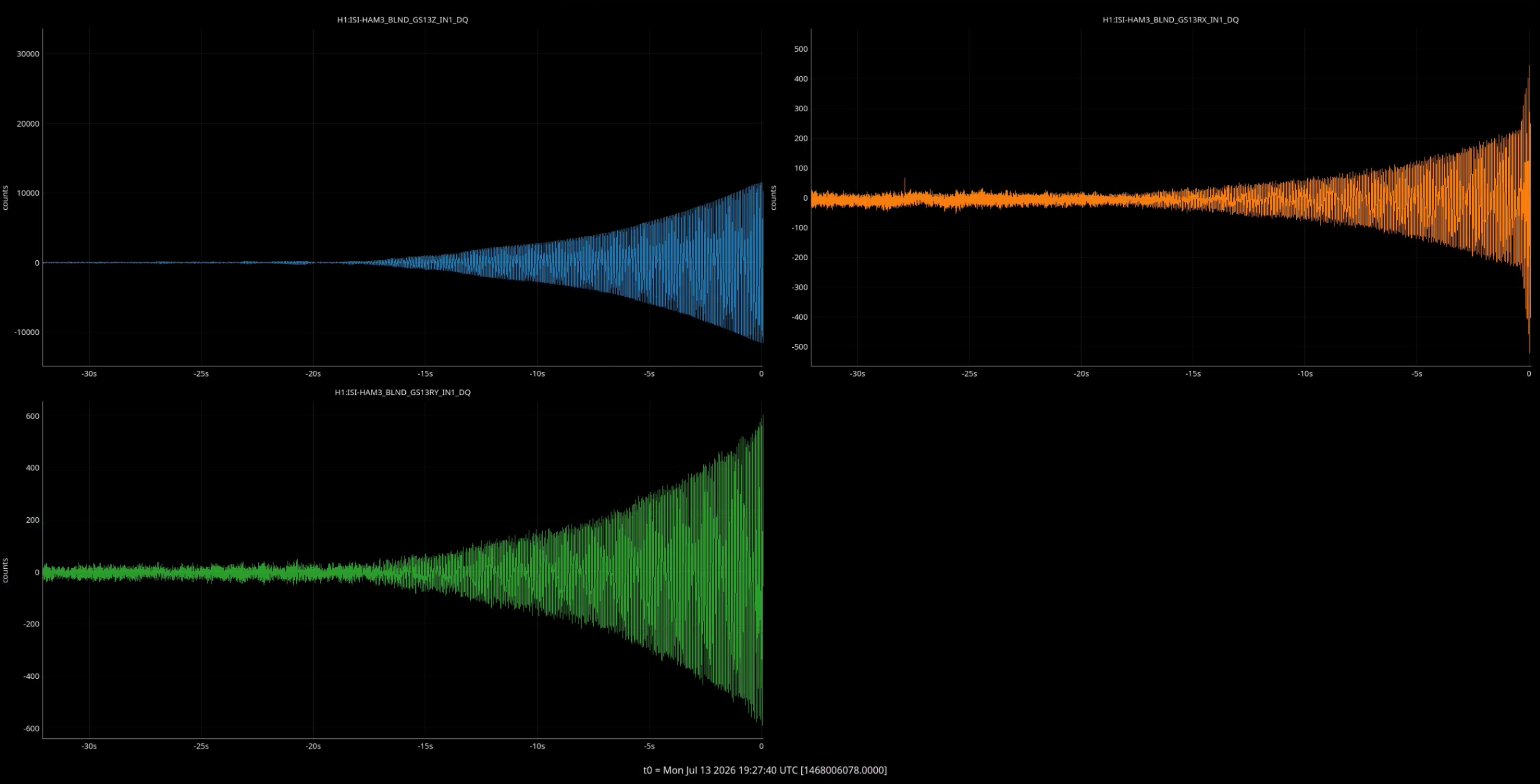
The RY blend filter was still set to the CRS damping path BLND7, so I changed it back to the nominal BLND4 path. Even after this change, the ISI was still ringing up.
Looks like the it's the Z loop that is unstable at 14.74Hz (see pictures). Having a good plant measurement will help retune the loop to avoid this ring up. If HAM3 needs to be isolated before then, the Z loop can be ran without the boost filter, which seem to be triggering the instability.
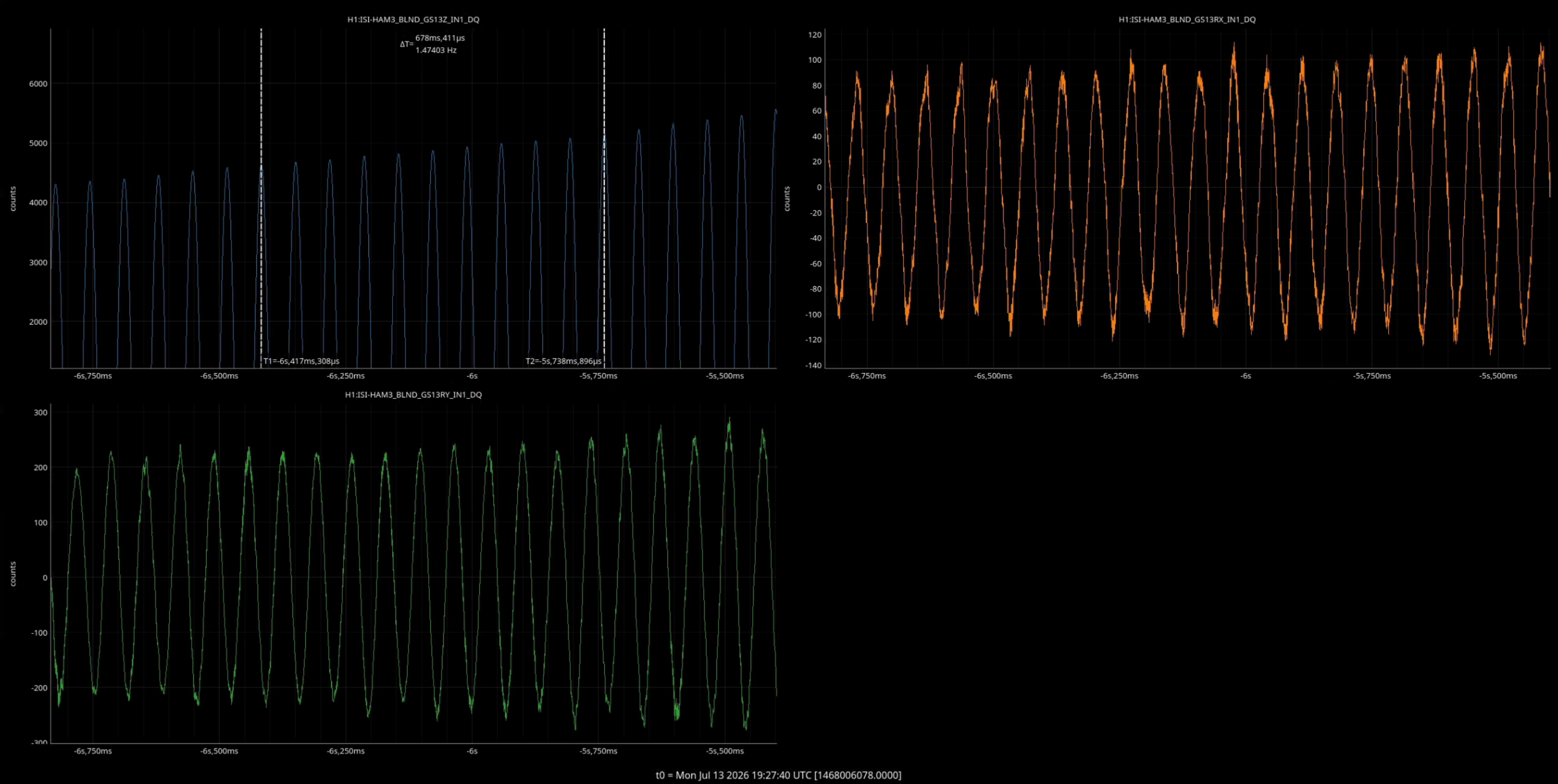
I think this ring up could be due to HEPI being locked on that chamber. I think this happened after the last vent as well. Could be that just adding a notch to the cps low pass will let us isolate the ISI. I will need a little bit of time to do some measurements.
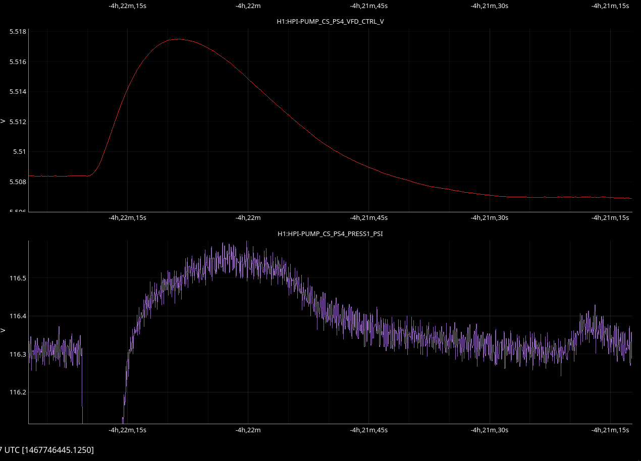
Over the weekend, there was another HEPI corner station dip/spike which prompted the verbal alarm notification. This last happend on Friday (alog 90984)
This time, the PS2_PRESS1 (red in attached plot) dipped by 10PSI before recovering. The bottom row of the plot are the controllers. Tagging SEI.
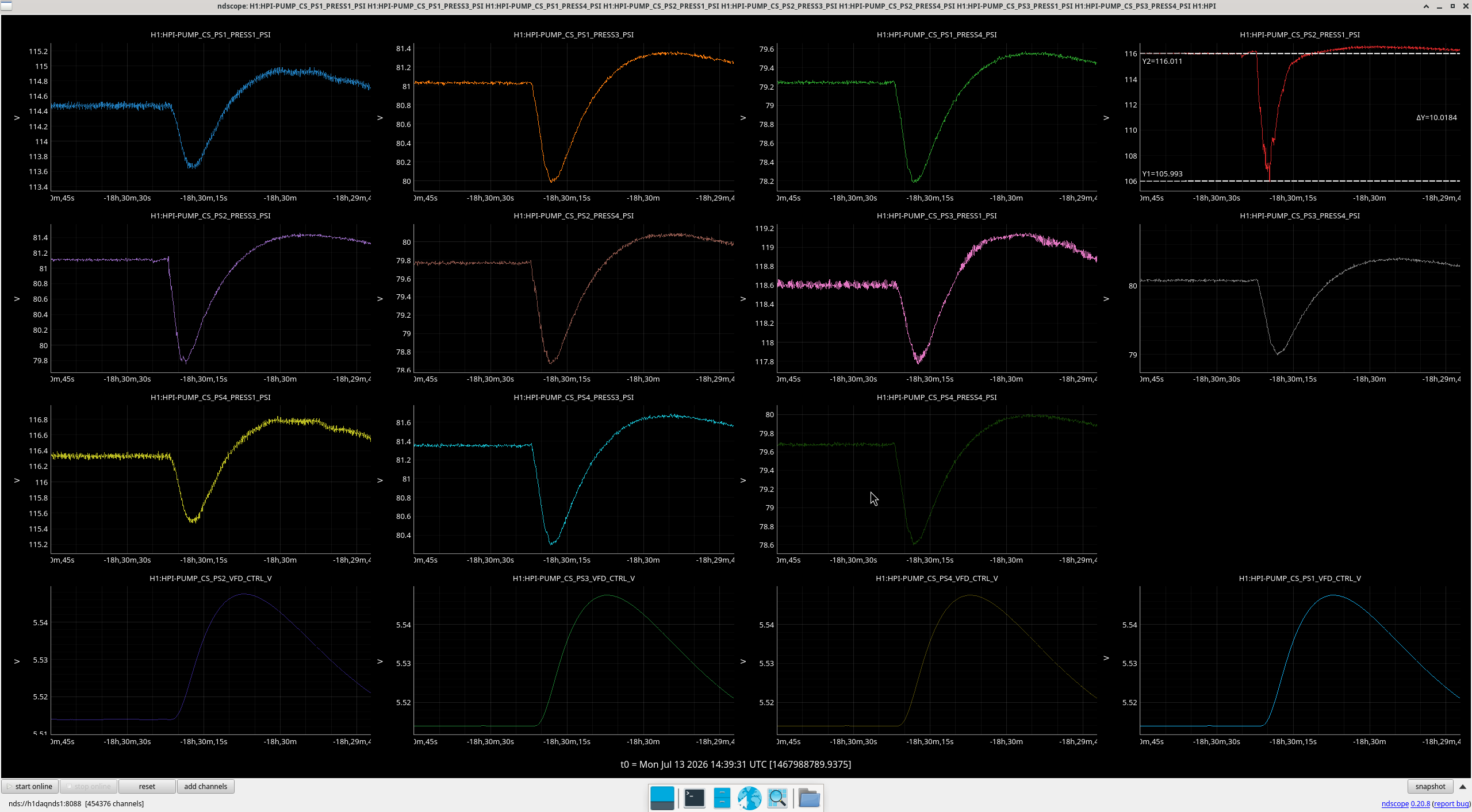
Ibrahim
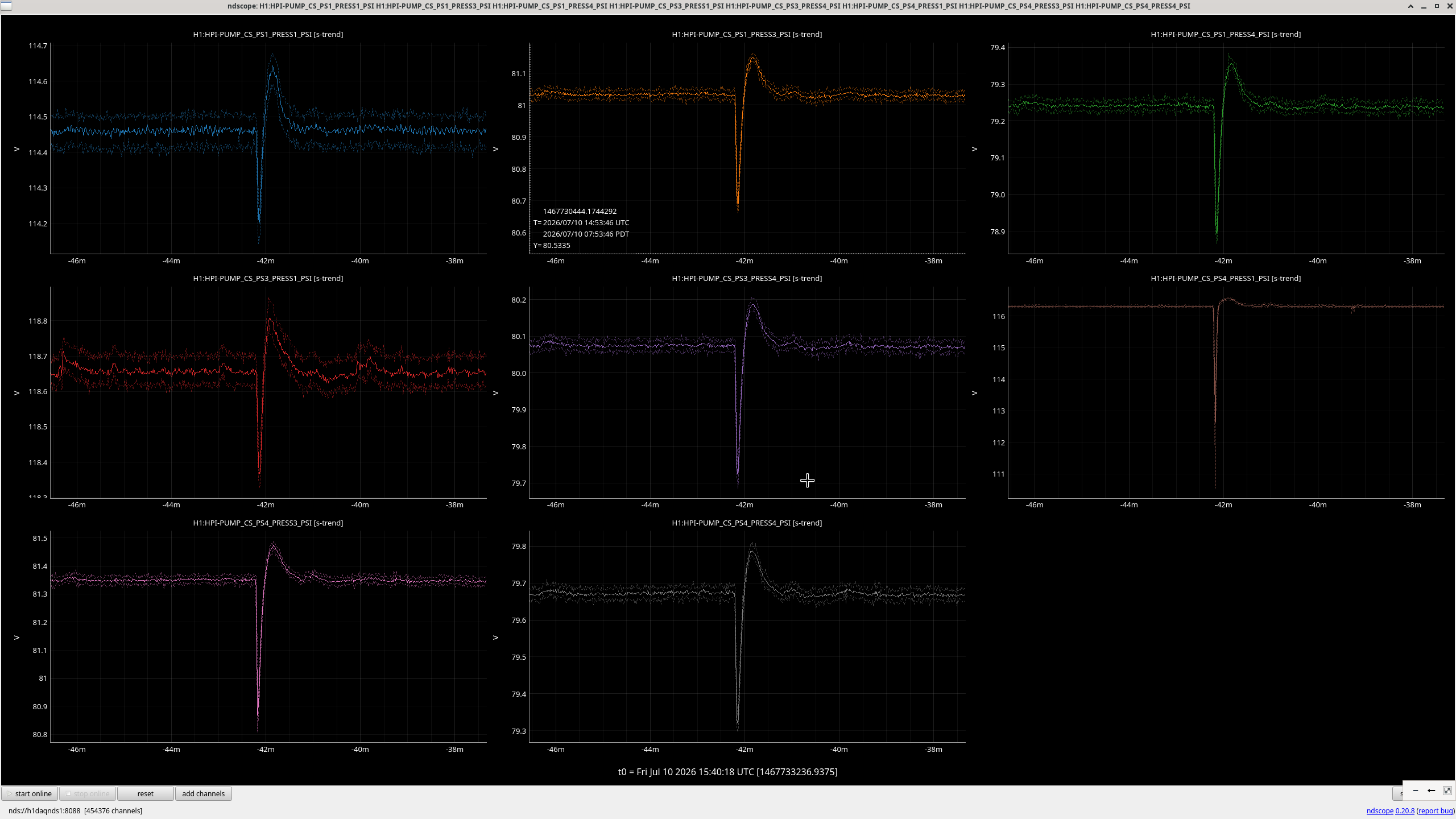
Got a message at 14:58 UTC to "Check HEPI pump station pressures".
At 14:58,
I checked the End Stations too but nothing was seen (also attached).

Per Jim's request, here are HEPI Pump Controllers at the time of the pressure dip/kick.
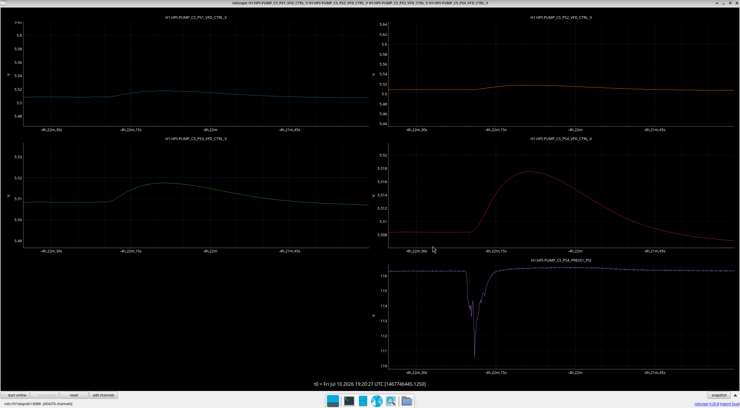
[Jim, Shoshana]
The CRS is currently aligned, suspended, balanced, and unlocked on HAM3!
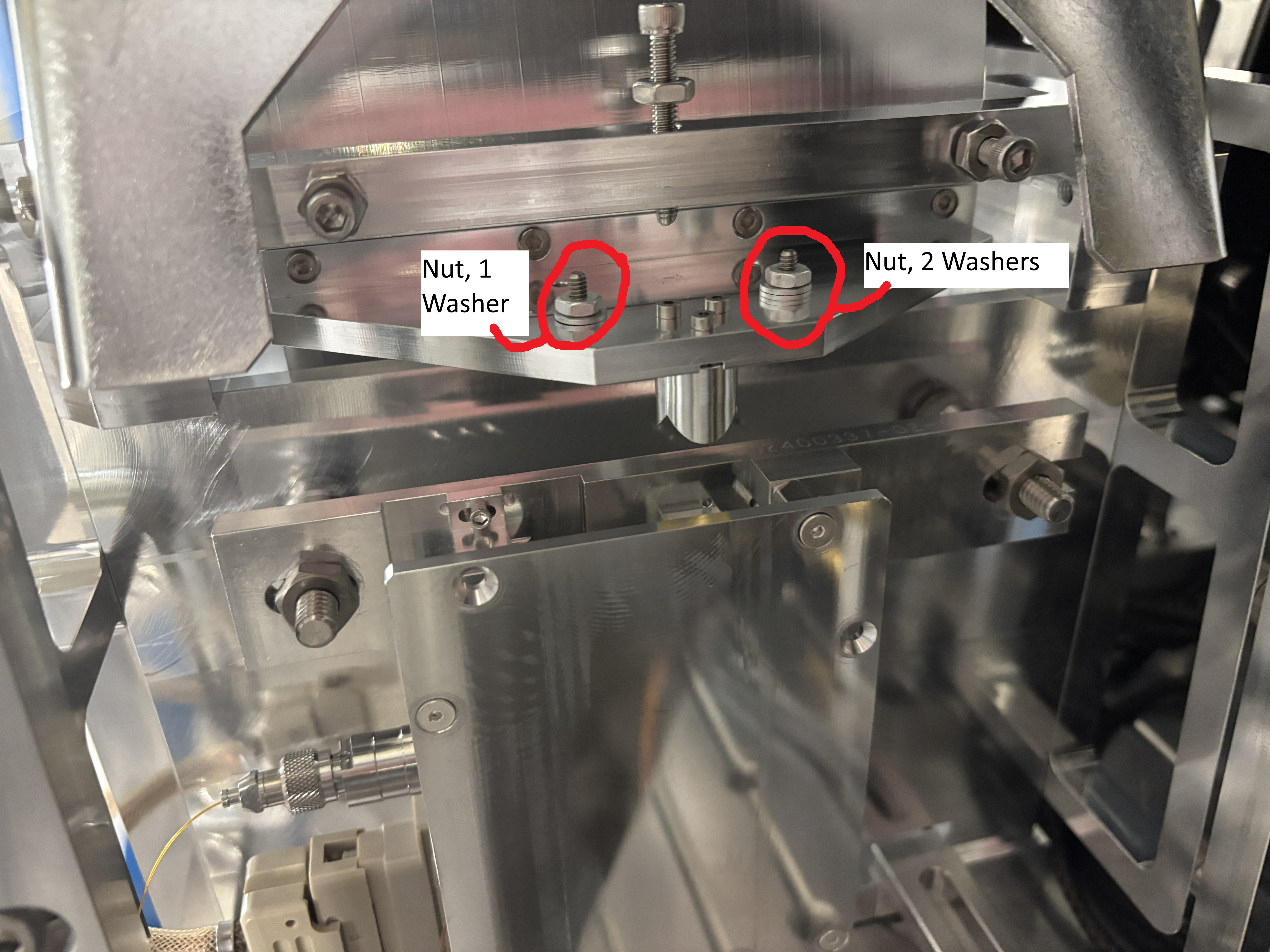
I aligned each HoQI as well as I could on the table, HoQI2 is slightly better than HoQI1, but it shouldn't be an issue. I also lowered the resonant frequency as much as possible, but I ended up running out of mass that I could easily remove from the bottom, so right now the resonant frequency is at ~25Hz. It's possible this raised frequency is because these flexures (21, 22) might be slightly thicker than the previous ones as they came from a different batch.
Tested the picomotor, moving the X value positive moves the mass to the left (towards HoQI1). We had it do three revolutions in both directions and the picomotor was able to couple with the mass adjuster while at maximum range (tilting fully to either side). We've also discovered that the GS13s outputs go crazy when the picomotor is running, which is something to be aware of.
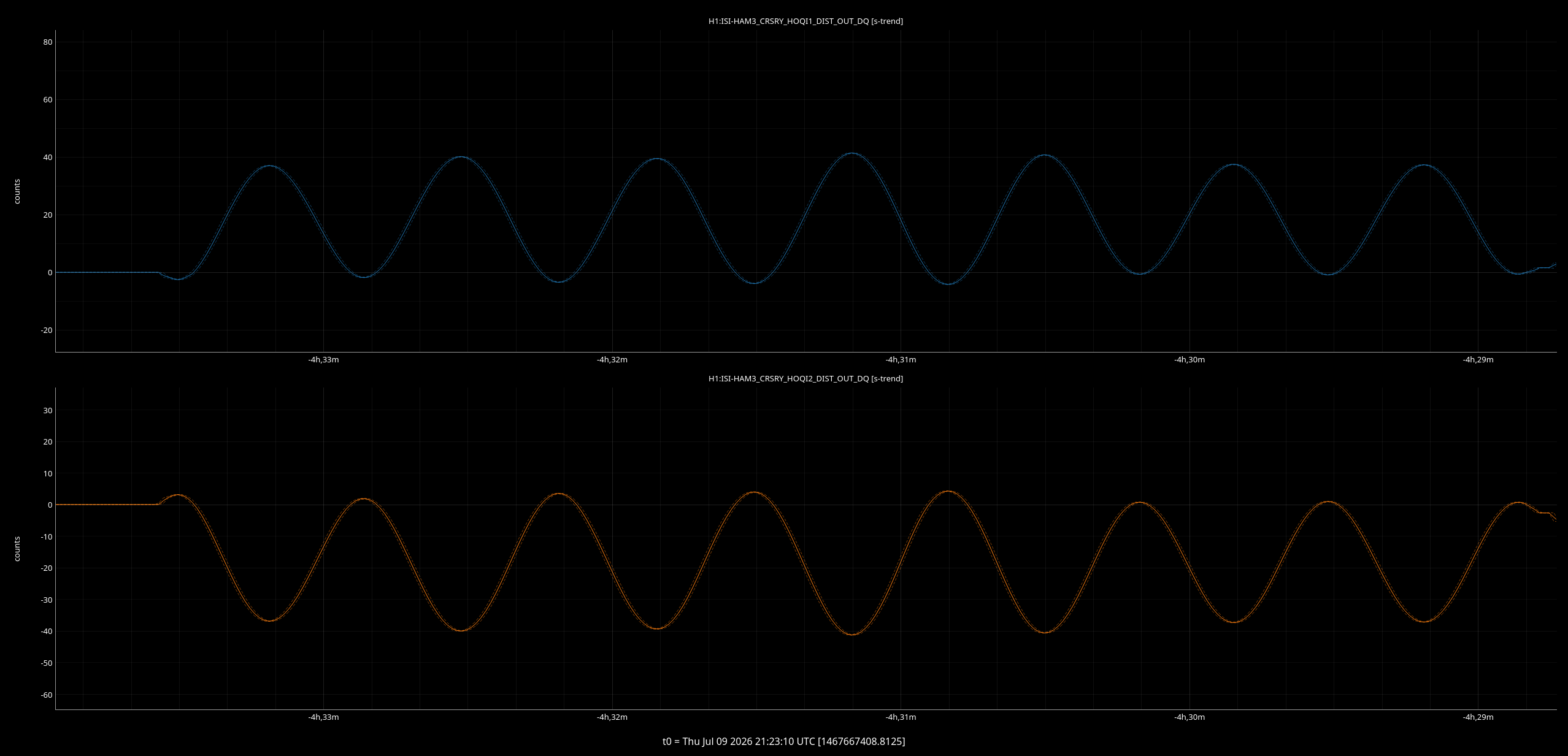
We've verified that voltage makes it to the damping capacitor plates on either side. We've also confirmed that in the HOQI{1,2}_DIST data increases as the corner cube gets closer to either interferometer (i.e. when the left corner cube (wing) gets closer to HoQI1, the HoQI1_DIST channel data increases)
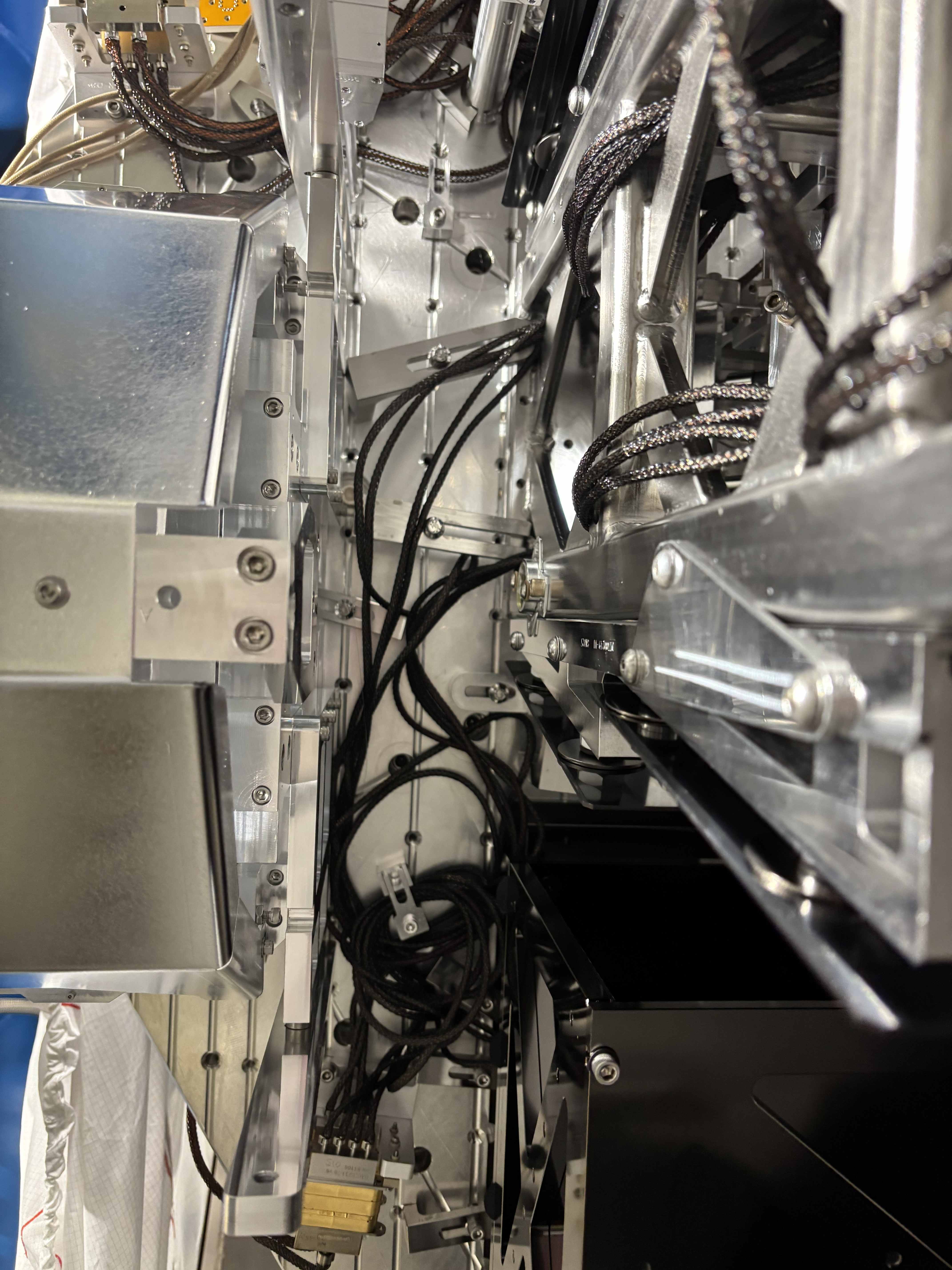
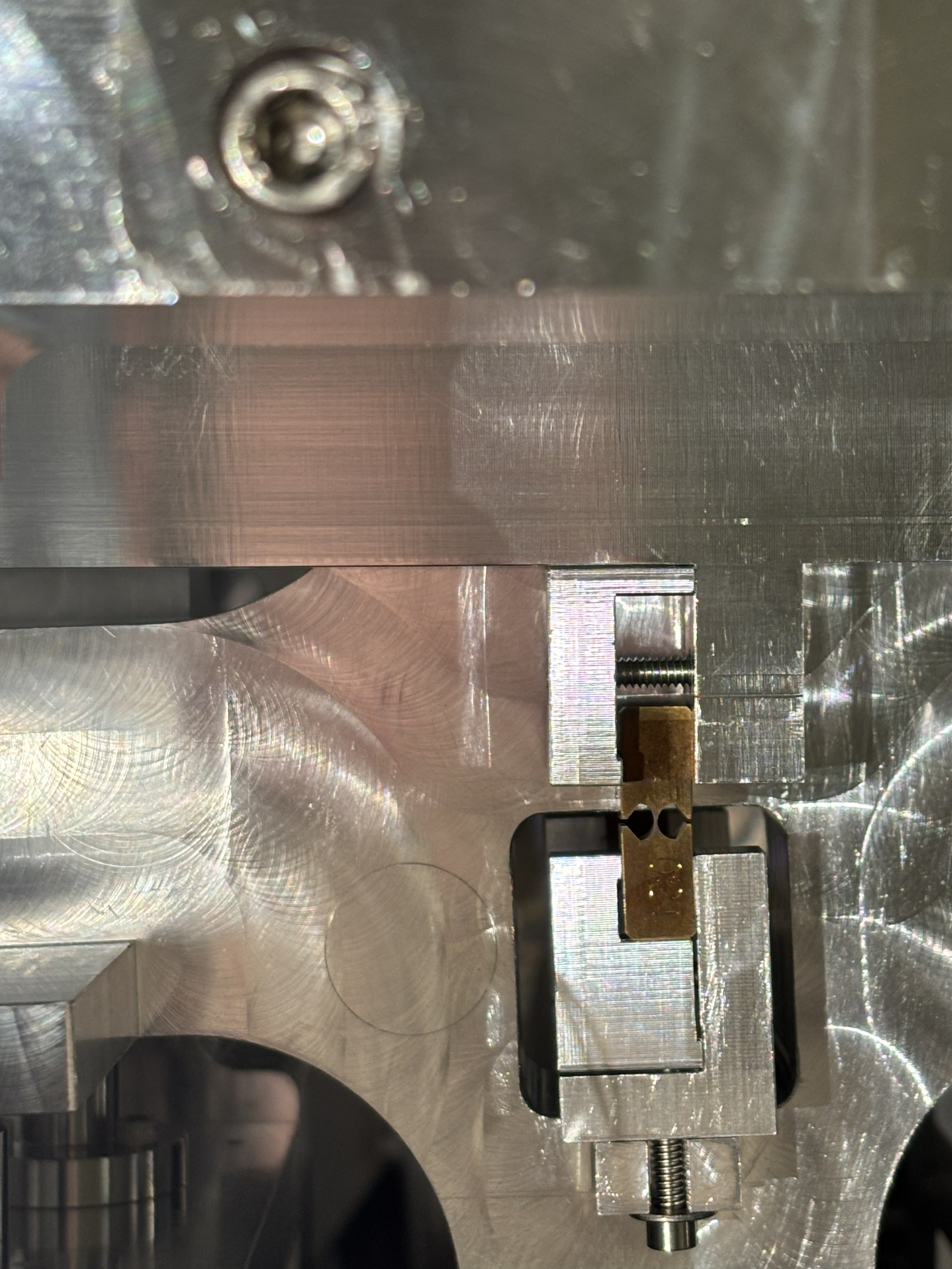
Attached are various photos of the CRS on the table for future reference, as well as a guide to all the balance masses currently on it.
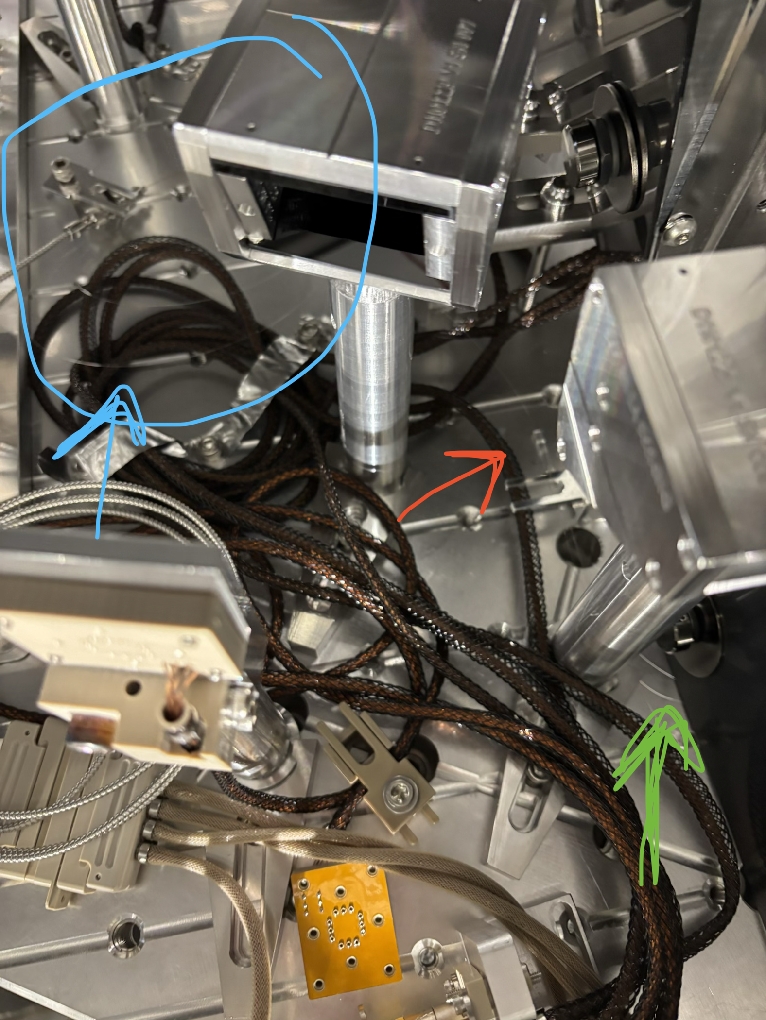
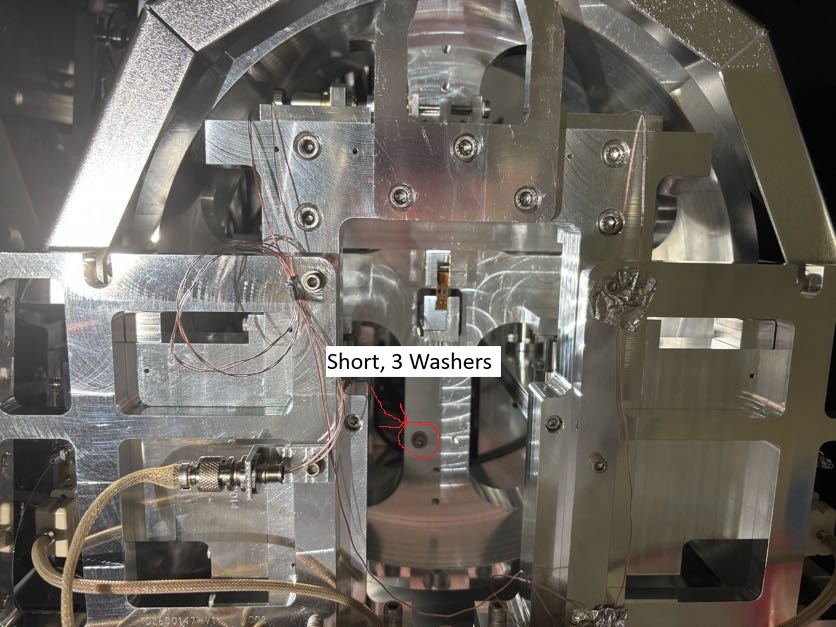

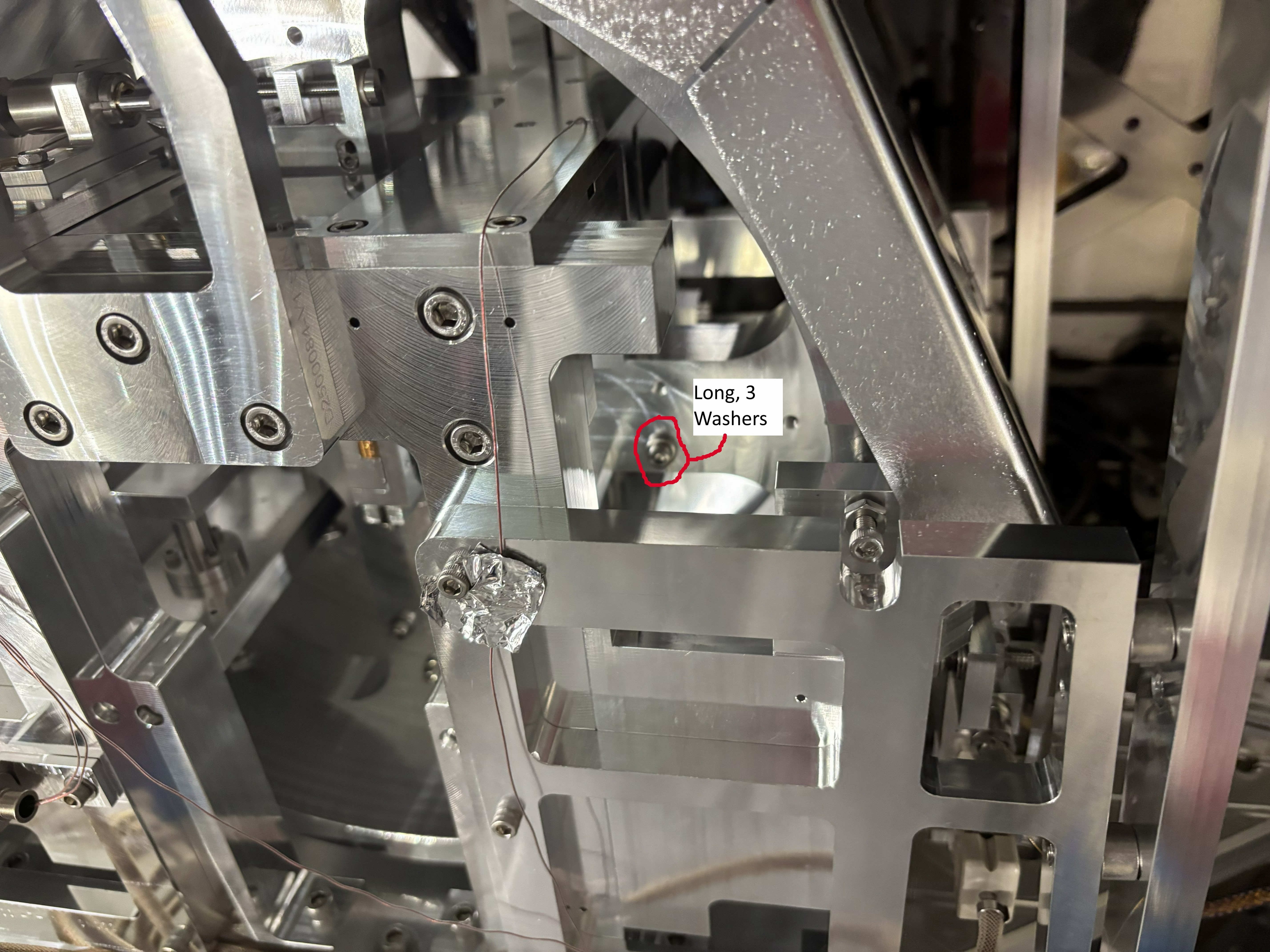

Notes on CRS commissioning tonight :

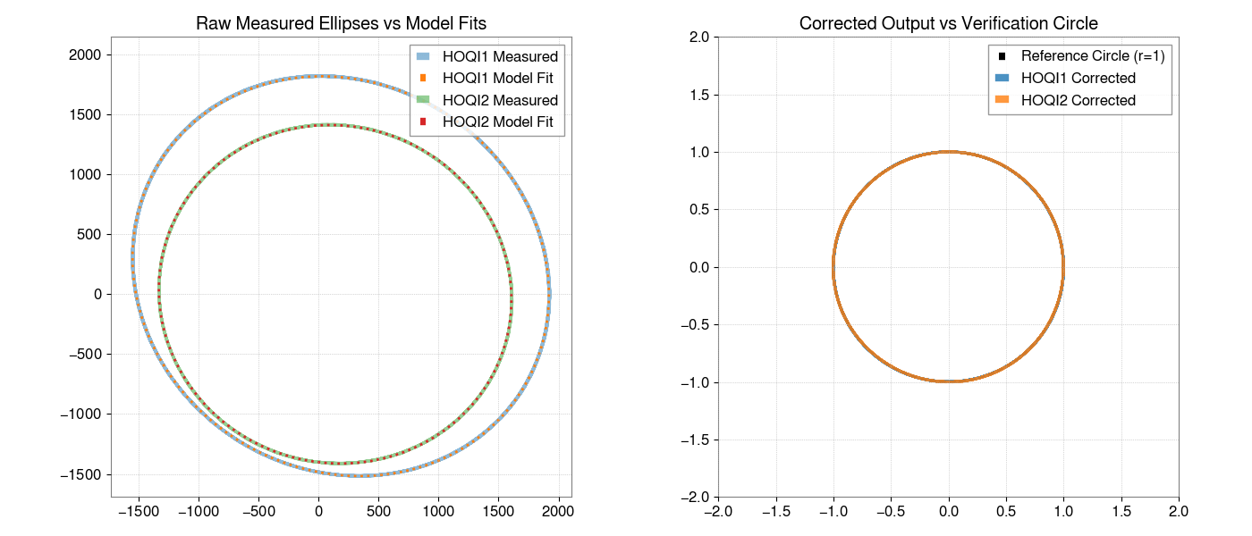

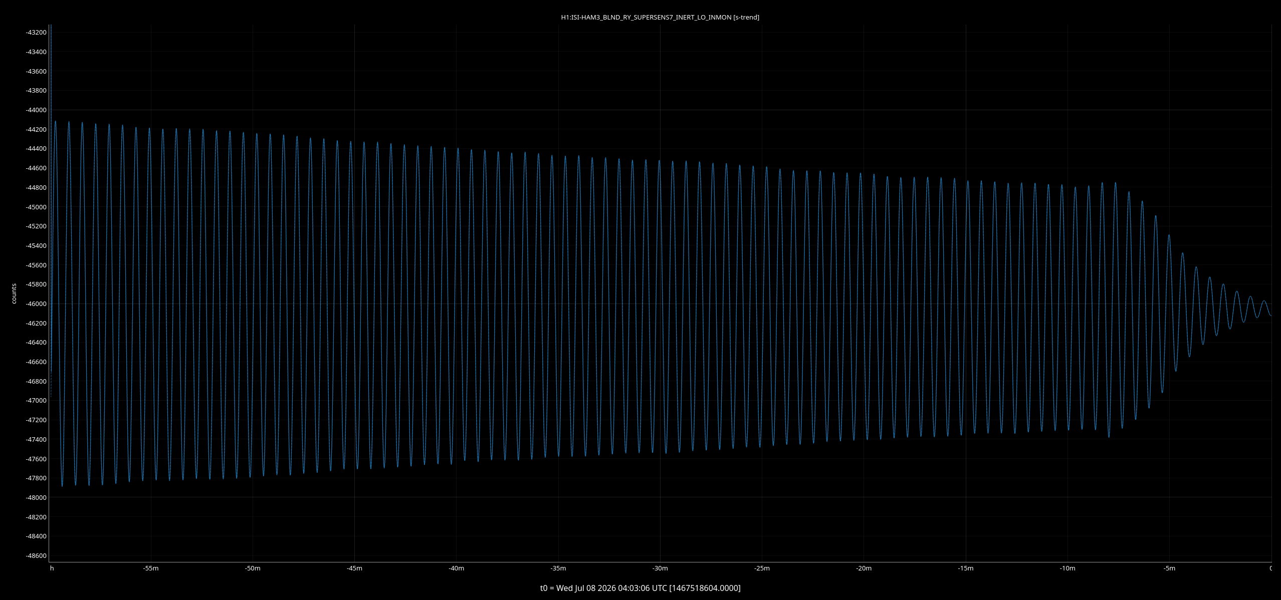


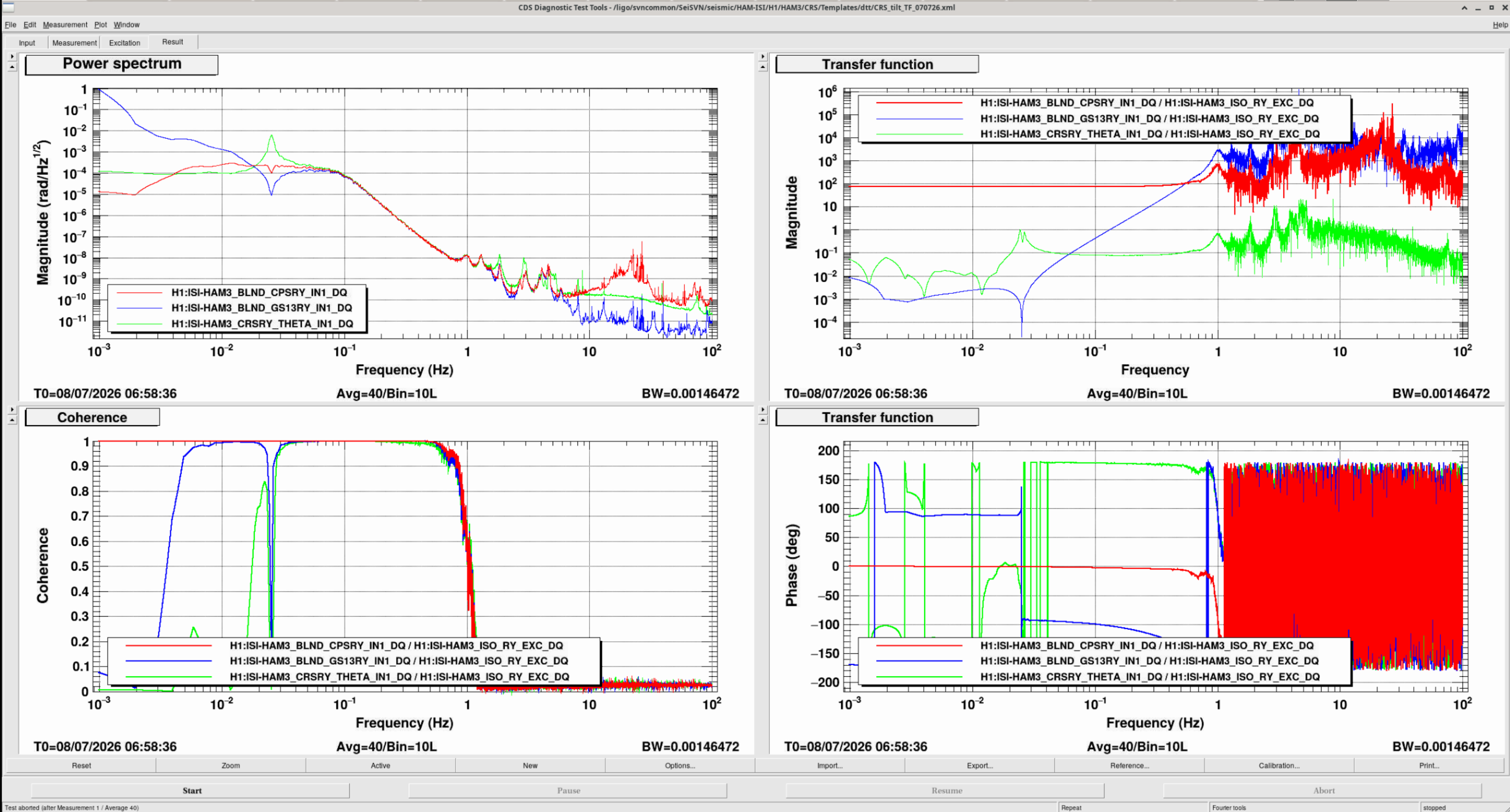
The overnight measurement is slightly better, but we are missing coherence below 15mHz which is probably due to too much air currents. The measurement is still good enough to fit and allow us to extract some physical parameters. Attached are updated data, scripts and the latest fit.
The zpk coefficients for this fit are :
zpk([0.0009 + 0.0766i 0.0009 - 0.0766i],[-0.0005 + 0.1584i -0.0005 - 0.1584i],1.0262)
My fitting script agrees. Looks like a delta value of 10 um.

CRS laser was turned on for ~5 minutes this morning to make sure the flexures didn't break while the doors were being put on HAM3, and it survived!
It's still pretty rung up, but that's unsurprising as there was a good amount of motion going on around the chamber
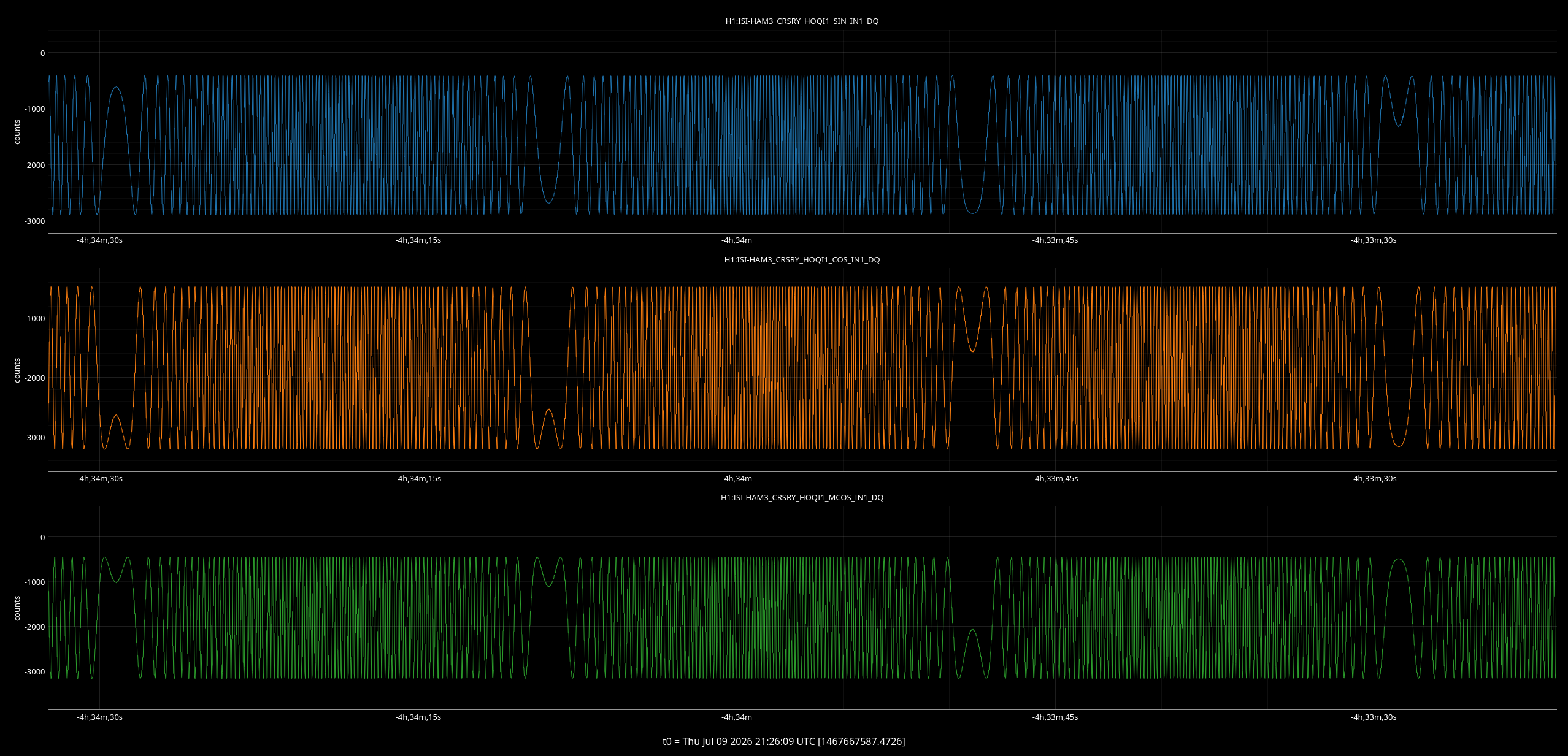
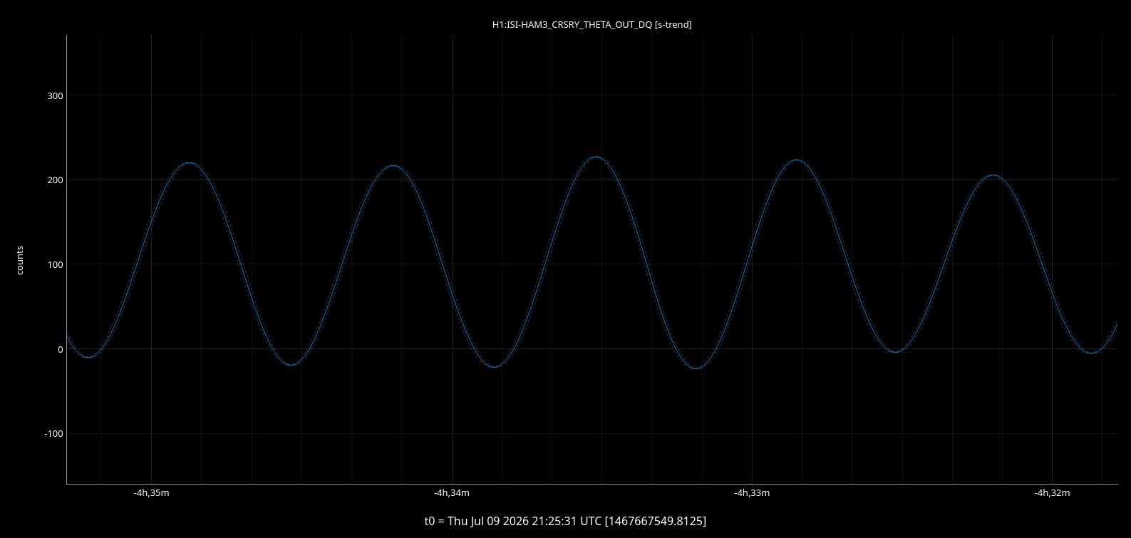
WP 13304.

"Reimage the Beckhoff machine controlling the HEPI pump controller at end X and the Beckhoff machine controlling the HEPI controller at end Y. Change the code and infrastructure to match what was done at the corner station."

I completed end X today. This completes the WP, except for a DAQ restart, which is planned for tomorrow. I will close the WP after that has been done.

All HEPI pump stations are up and running on PID control.
This work permit has been closed.


Sure enough there was a brief pressure dip in the CS HEPI pump pressures that it immediately recovered from. The 4 pumps and the supply and return all see it.
Looking into this a bit further, pump 4 sees the largest pressure change. Local IPS sensors on HAM3 see this change, but Jim said that their locationmon channels did not see it.