BS horizontal wedge doesn't have any couterpart Y path. Any horizontal beam shift on the BS will cause MICH path difference because of this wedge.
(CPY has a horizontal wedge but it's a mirror image of CPX about BS HR surface. ITMY has a vertical wedge but again it's a mirror image of ITMX.)
This effect doesn't look small, and a rough calculation shows that the HPO jitter peaks from DBB (but not broad humps seen in DBB) are consistent with what we see in DARM.
----
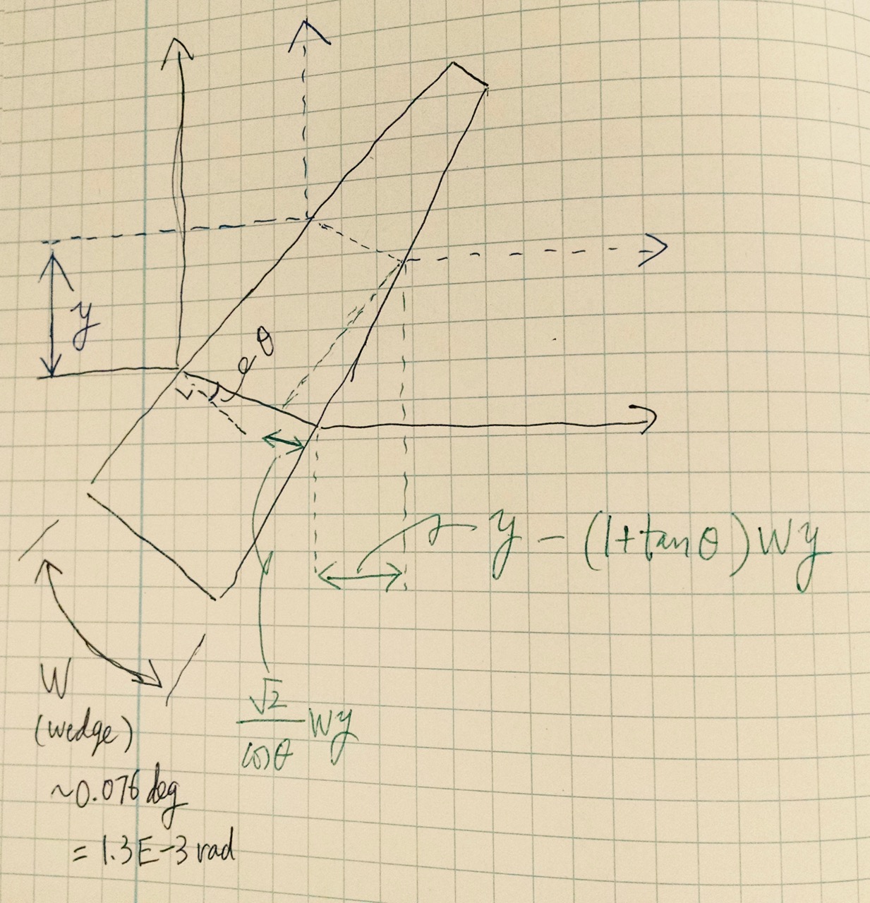
In the attached cartoon, when the beam on the BS is shifted in Y direction by y (blue line), the optical single-trip distance from the beam spot on the BS to ITMX gets shorter than to ITMY by:
EQN1: MICH = n*yW*sqrt(2)/cos(theta) - yW*(1+tan(theta)) ~ 0.7896yW = 1.0E-3*y
where W=1.3E-3 rad is the wedge, n=1.4496 is the refractive index and theta=29.2deg=0.5096rad is the angle of refraction.
DARM will only see about (1-rI)/(1+rI) of MICH where rI is the amplitude reflectivity of the ITMs, which is sqrt(0.986):
EQN2: DARM=MICH*(1-rI)/(1+rI) = 3.5E-3*MICH ~ 3.5E-6 * y.
Because of this, DARM should have a flat coupling to YAW displacement on BS.
Instead of the displacement y, we'll use the displacement A which is just the displacement normalized by the beam radius on the BS (53.4mm):
EQN3: DARM=3.5E-6*53.4[mm]*A = 1.9E-7 [m] * A.
----
Now, let B be a normalized misalignment parameter out of HPO (i.e. HPO jitter), e.g. B=disp/waistRadius+ i* angle/divAngle. Note that abs(B) is conserved unless 01/00 mode ratio is altered.
PMC gives us 1.6% HOM01 suppression in amplitude (T0900616).
For IMC there's some difference for PIT and YAW due to additional sign flip on top of Gouy shift per round trip, but PIT suppression is about 0.5% and YAW is 0.4% in amplitude assuming that the common round trip Gouy shift is 102 deg.
For PRC, assuming carrier recycling gain of 30, PRM reflectivity of 97% and the round trip Gouy shift of 32.5 deg, HOM01 suppression is 5.7% in amplitude.
PMC, IMC and PRC combined, HOM01 suppression is 3.7e-6 for YAW, 4.6e-6 for PIT.
Though A cannot be known without knowing the Gouy shift from HPO to BS, since |B| is conserved except through cavities, we can set the upper bound on |B| using the HOM suppression through PMC, IMC and PRC as
EQN4: |A| < 3.7e-6 * |B|
therefore upper bound on DARM
EQN5: DARM < 7E-13 [m] * |B|.
DBB measurements of B are available in alog, e.g. alog 29754 (direct link to the HPO jitter plot is here).
If you look at 1kHz peak which does not appear in DBB RIN measurement, the peak height is somewhere between 5E-6 to 1E-5, and using EQN5 and these numbers,
EQN6: DARM < 3.5 to 7E-18 [m/sqrtHz] at 1kHz peak.
In DARM spectrum, 1kHz peak is visible at or somewhat above 1E-19 [m/sqrtHz], so it seems consistent with EQN5.
----
Caveats:
IF the broad noise in DBB jitter measurement is actually jitter, assuming the same jitter coupling as the above, you should see the huge broad thing in DARM, which we do not.
This coupling only applies to YAW. As for PIT, there could be similar coupling mechanism if ITM wedges don't cancel with each other, but the imbalance is only 0.001 degree.
MICH is not the only thing that is modulated by this, SRCL and PRCL are simultaneously modulated. Full simulation might be useful.
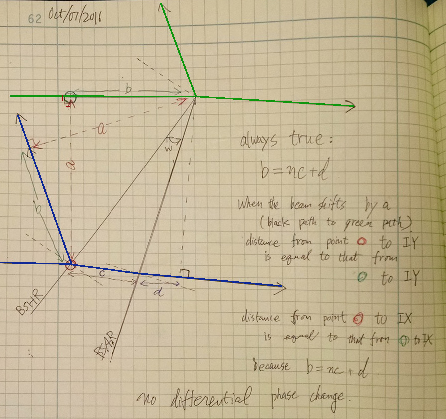
Update: Wrong.
If you do the correct calculation there's no differential phase change (see attached). In the above entry I ignored the fact that BS transmission is deflected relative to the incident.