peter.king@LIGO.ORG - posted 10:18, Sunday 09 October 2016 (30349)
trip data
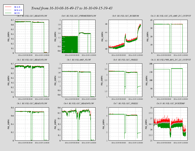
OverallView.png is the top level signals related to the cooling system. Clearly there is an oscillation with the flow in the
power meter circuit that is not apparent in the front end cooling circuit.
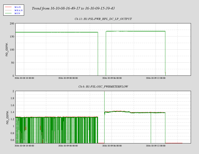
PowerMeterCircuitFlow.png shows the laser output and the flow in the power meter circuit.
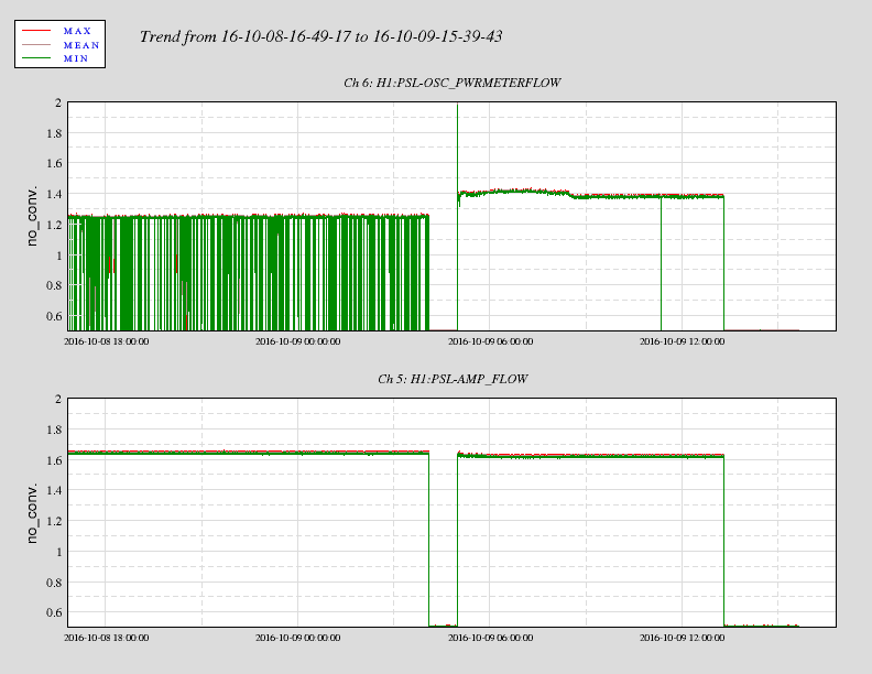
Flows.png shows the flows in the power meter circuit and the front end circuit.
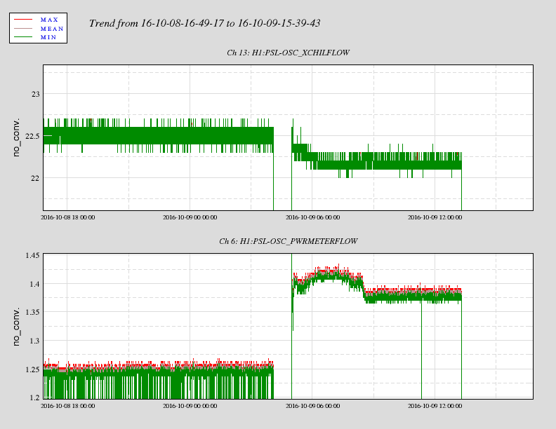
CrystalChillerFlow.png shows the flow in the power meter circuit and the flow from the crystal chiller.
Unfortunately the laser was being restarted when I got in, so I cannot tell if the error condition on the Beckhoff terminal
that reads the flow rate was latched or not. In this particular case it appears that the problem lay with the flow rate in the
power meter circuit and not the chiller, at least at first glance.
At this point the prime candidate for installation of the "electronic" flow sensor would be in the power meter cooling
circuit.
Images attached to this report