Peter, Kiwamu,
We have taken out the PD A photodiode out of the ISS inner loop box and placed it at a location where the PWR_EOM photodiode was. We confirmed that we can close the loop with the moved PD A.
[New setup]
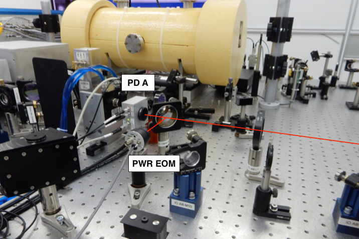
We opened up the inner loop box and removed the base plate on which the two photodiodes sat. Then we took out only PD A from the base plate while leaving PD B mounted on the base plate. We put the base plate back into the inner loop box. A black glass beam dump was placed at the location where PD A used to be. Careful: because we could not find a good screw hole, we could not clamp down the black glass beam dump which is currently just sitting on the base plate.
We placed PD A to the location where PWR EOM (Thoralbs PDA55) had been. We rerouted all the associated cables for PD A (a 5 pin lemo, 2 normal lemos) to the new location. We measured the beam power at this location to be 8 mW. Because this is too much for PD A (which we think typically runs with 1 mW), we installed an ND filter on the front panel of PD A (see the picture).
A few more pictures are available at ResourceSpace.
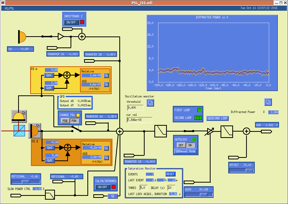
[ISS loop closed with PD A]
Here shows a screenshot of the setup for closing the inner loop with PD A. The gain slider needed to be a 12 dB higher (which still smells like a factor of two calibration error...) than the usual. The ref signal for PD A needed to be -0.46.
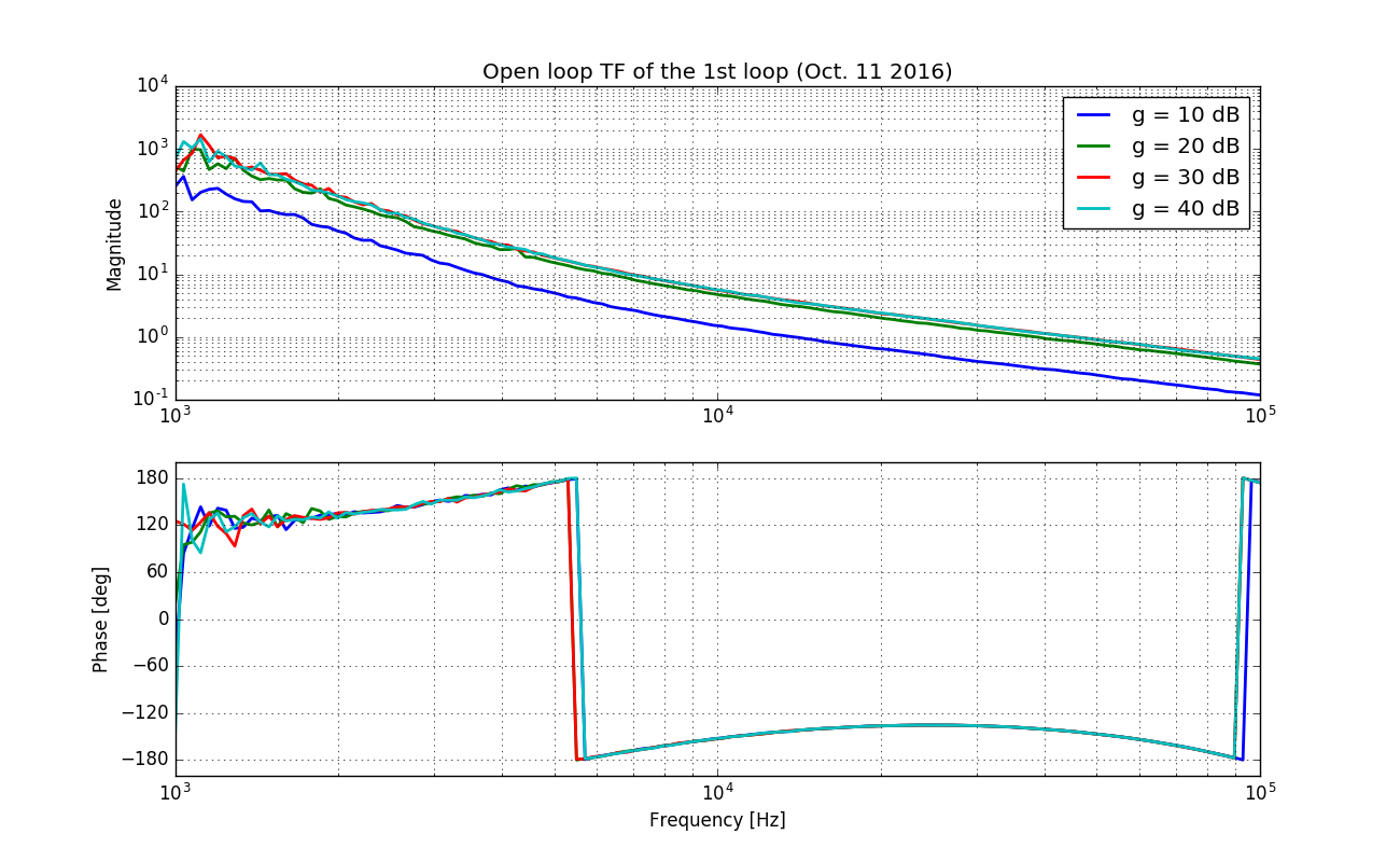
Here are some plots of the open loop transfer function with PD A used as the in-loop sensor. A gain of more than 20-30 dB in the gain slider actually does not do the job -- needs more investigation. The ugf is about 46 kHz with the gain slider set to 30 dB. Note that when PD B was in use, the ugf had been 54 kHz (29942).