jenne.driggers@LIGO.ORG - posted 01:48, Friday 14 October 2016 (30523)
Prep for TCS tuning tests
We were basically ready to start TCS tuning tests, but we can't relock the IFO :( Since it took me a while to get these settings, this will basically be a note-to-self of what I had set up, so that I can do it again more quickly tomorrow.
AS port OSA
- Sheila helped plug in the OSA that is at the AS port to the roaming wireless router (that belongs with the gpib setup - only having one of these is a problem!).
-
We can now use Jamie's script (documented in alog 29563) to pull the data.
-
tektronix download -c 'ch2' ~/LHO_work/2016_10_13_OSA_AS/ 0 60 - In the above, 0 tells it to keep downloading data until we crtl-c to quit. 60 tells it to get data once every 60 seconds. The help file is very detailed.
-
- We forgot to set the vertical axis ranges for channels 2 and 3 differently, so right now we can only see the 45MHz peaks clearly. We should zoom one of the channels in so that we can see the 9MHz peaks.
-
Gabriele has a script that will pull all the data from a folder, find the peak height and plot the peaks as a function of time.
- Currently it lives in /ligo/home/gabriele.vajente/2016_10_13/sideband_amplitudes.m
- Give the script the peak location for both upper and lower sidebands in the first data file, as well as about how much they move between data sets, and his script will find the max value in a range based on that.
- We ran it for about 45 min while I was still setting up, so without any TCS changes, and saw that the 45MHz sidebands started out pretty imbalanced, but were moving toward being more balanced as the IFO thermalized.
- The goal will be to tune TCS such that the 45MHz peaks are well balanced.
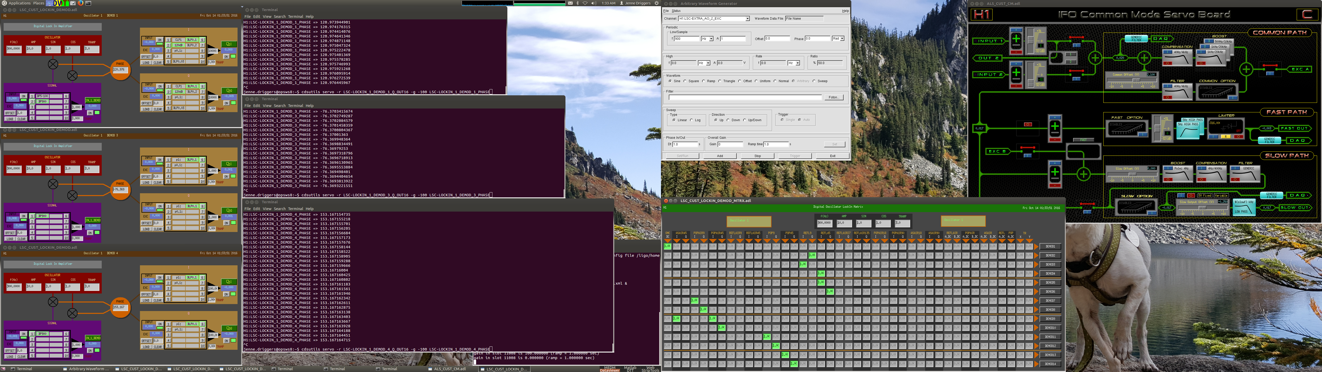
Frequency line
-
Similar to what was done in September (alogs 29553, 29509), I used awggui to inject a line at 900Hz into the Refl Servo, 100 counts amplitude.
- H1:LSC-EXTRA_AO_2_EXC is plugged into Exc A of the Refl Servo's common mode board, and H1:LSC-REFL_SERVO_COMEXCEN is enabled.
-
I used the LSC OSC1 to demodulate signals at this frequency.
- The frequency was set to the same 900 Hz, but the LSC output matrix didn't send the oscillator signal to any optics.
- Demod 1 looked at OMC DCPDs, Demod 3 looked at REFL9I, and Demod4 looked at REFL45I (this is the same convention as in alog 29553).
-
cdsutils servos were used to change the phase of the demodulators to zero the Q-phase signal.
-
cdsutils servo -r LSC-LOCKIN_1_DEMOD_1_Q_OUT16 -g -100 LSC-LOCKIN_1_DEMOD_1_PHASE -
cdsutils servo -r LSC-LOCKIN_1_DEMOD_3_Q_OUT16 -g -100 LSC-LOCKIN_1_DEMOD_3_PHASE -
cdsutils servo -r LSC-LOCKIN_1_DEMOD_4_Q_OUT16 -g -100 LSC-LOCKIN_1_DEMOD_4_PHASE
-
- The goal will be to tune TCS such that the frequency line is minimized in DARM.
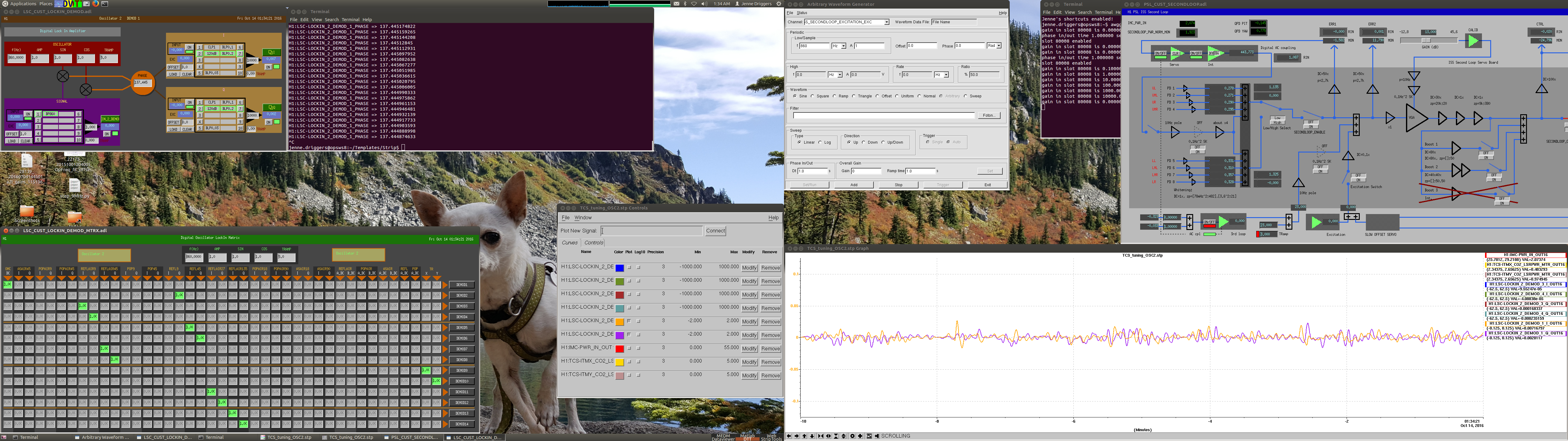
Intensity line
-
I used awggui to inject a line at 860Hz, 10,000counts into the ISS second loop.
- H1:PSL-ISS_SECONDLOOP_EXCITATION_EXC
- H1:PSL-ISS_SECONDLOOP_EXC_SWITCH_MON enabled, but first H1:PSL-ISS_SECONDLOOP_REFERENCE_VALUE set to zero so that I wouldn't give the ISS a giant kick.
-
I used the LSC OSC2 to demodulate, but only Demod 1 for OMC DCPDs. Same situation as the freq line - set the frequency of the LSC oscillator, but don't send the signal anywhere in the output matrix.
-
cdsutils servo -r LSC-LOCKIN_2_DEMOD_1_Q_OUT16 -g -1 LSC-LOCKIN_2_DEMOD_1_PHASEto zero the Q-phase signal.
-
- The goal will be to tune TCS such that the intensity line is minimized in DARM.
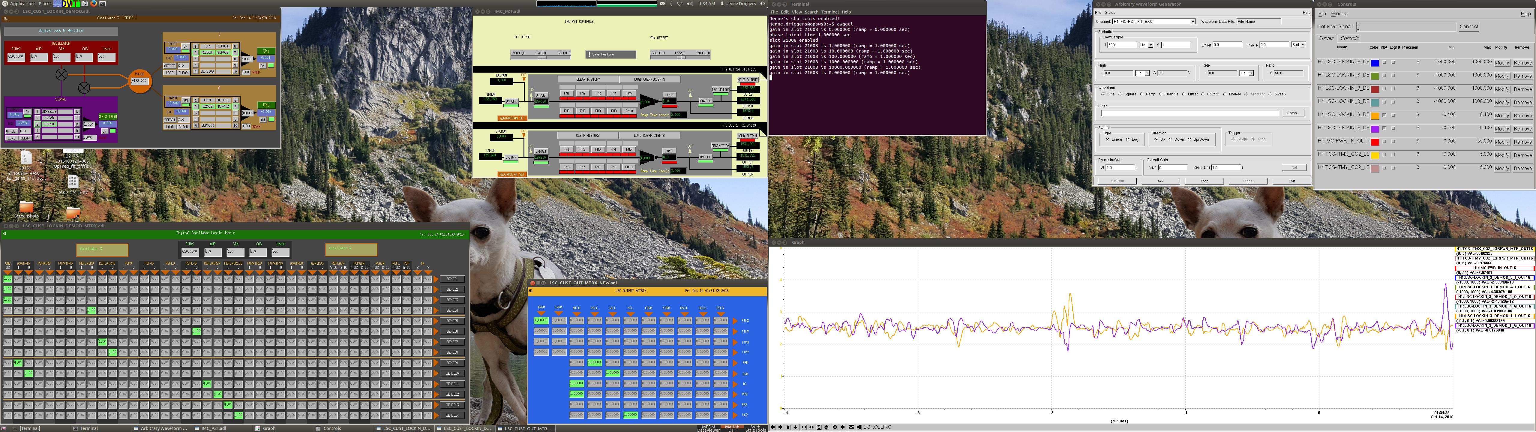
Jitter line (pitch)
-
I used awggui to inject a line at 820 Hz, 1000 counts into the PSL PZT in pitch.
- H1:IMC-PZT_PIT_EXC
-
I used the LSC OSC3 to demodulate, but only demod 1 for the OMC DCPDs.
- Since trying a larger amplitude for this line broke the lock, I didn't set the cdsutils servo.
- The goal will be to tune TCS such that the jitter peak is minimized in DARM.
Obviously, the goal is to find a perfect TCS place where all the couplings are minimized at the same time, and the giant peaks in DARM are minimized. We'll see if that is possible.
Attached are screenshots of my 3 desktops, to remind myself of any other settings that I've not written down. Note that the IFO was not locked when the screenshots were taken.
Images attached to this report