Sheila, Jenne, Kiwamu
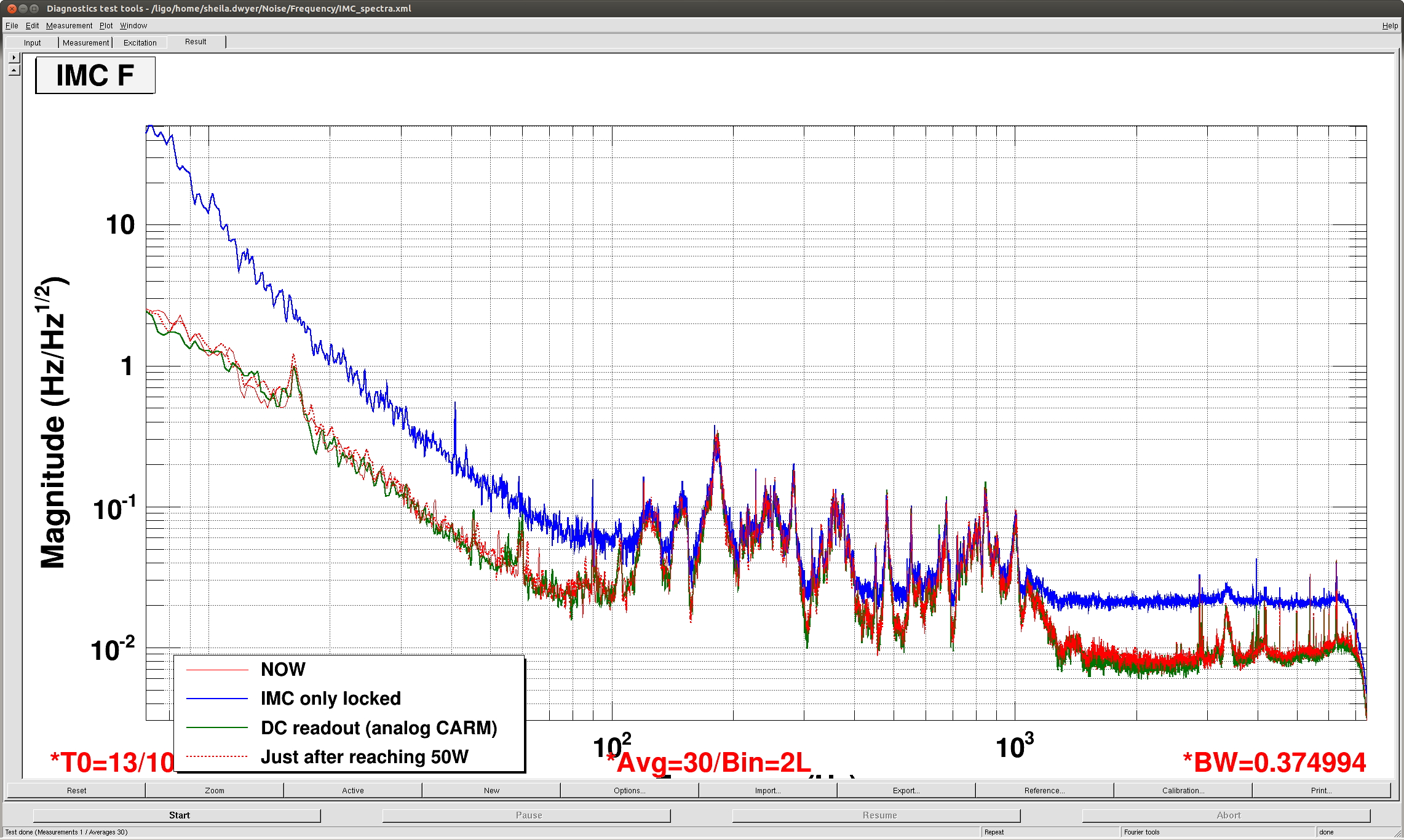
Attached is a spectra of IMC-F in different configurations. (MC locked at different powers, DC readout, low noise) From 100 Hz to about 1 kHZ, the spectrum of IMC F doesn't change much at all in all of these different configurations. So the IMC control signal is not dominated by REFL9 sensing noise in full lock, and probably represents the real frequency noise at the input to the IMC.
We can do a better job later, but if we assume this is really frequency noise we can roughly calibrate this into Watts on REFL 9I:
At 1kHz: 0.1Hz/rt Hz Frquency noise arriving at IMC (which is roughly consistent with measurements in P1100192, Fig 8) Suppresion of IMC loop: 1/200 (alog 22188) Supression of CARM loop (alog 22188, our ugf is now more like 8kHz) roughly a factor of 1/30. We can scale the DC optical gain of 0.017W/Hz used in 22188 by sqrt(2) to account for the factor of 2 increase in input power and the 6dB modulation index decrease since then. Taking into account the coupled cavity pole at 0.5 Hz give another factor of 1/2000:
0.1Hz/rtHz(1/200 Hz/Hz IMC supression )(1/30 Hz/Hz CARM suppression) (0.024*0.5/1000)W/Hz = 2e-10 Watts/rt Hz signal on REFL 9I or 1.7e-5 Hz/rt Hz of residual frequency noise expected.
We can repeat this at 400 Hz:
0.03Hz/rtHz(1/600 Hz/Hz IMC supression )(1/300 Hz/Hz CARM suppression) (0.024*0.5/400)W/Hz = 5e-12 Watts/rt Hz signal on REFL 9I or 1.7e-12 Hz/rt Hz of residual frequency noise expected.
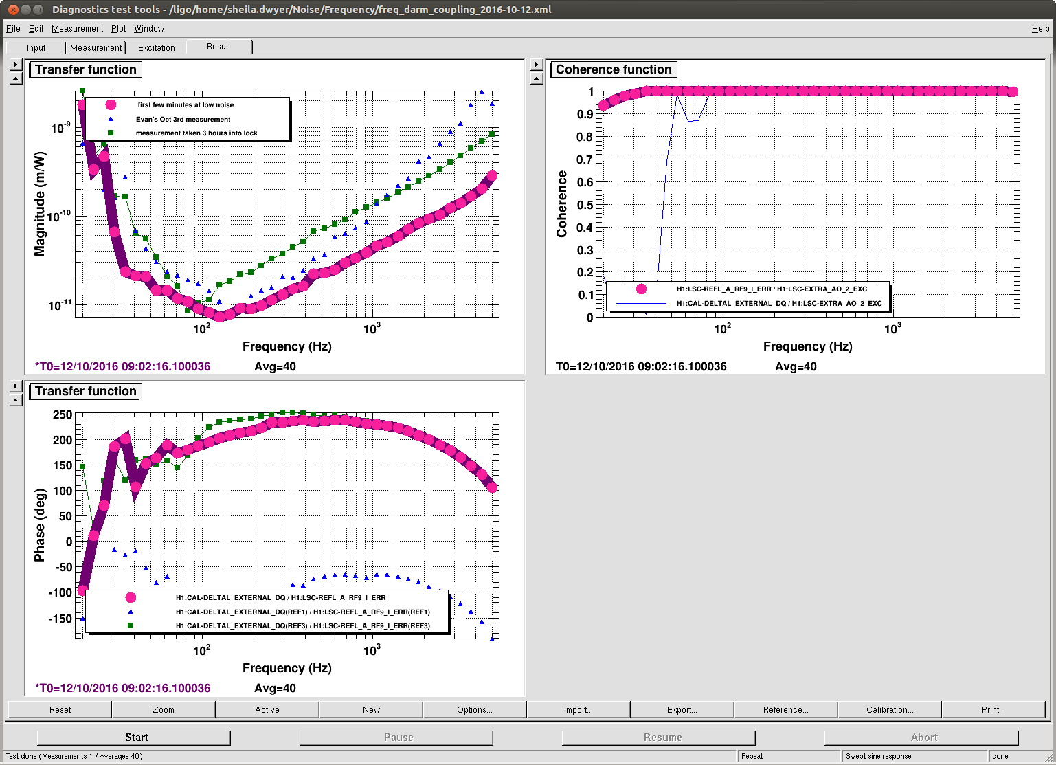
Comparing this to Evan's in loop measurement of the CARM noise using REFL control, (here) it is close at 1 kHz but not at 400 Hz. You can also compare it to the transfer functions from REFL 9I to DARM posted here, and see that at 1 kHz the expected frequency noise is of the order of 5e-20 m/rt Hz at 1 kHz.
The main message: It is probably worth making a projection for frequency noise in DARM using IMC-F to estimate the frequency noise after the ref cav, because a very rough estimate says it could be within a factor of 2 of DARM at 1kHz.

I just quickly tried changing gains on the FSS while watching the IMC F spectrum in full lock. The features from 100 Hz-1kHz do not change in IMC F as the FSS gain at these frequencies changed by 7 dB, so we are not limited by gain in the FSS at these frequencies. The FSS might have been oscillating at both the highest and lowest gain settings here.
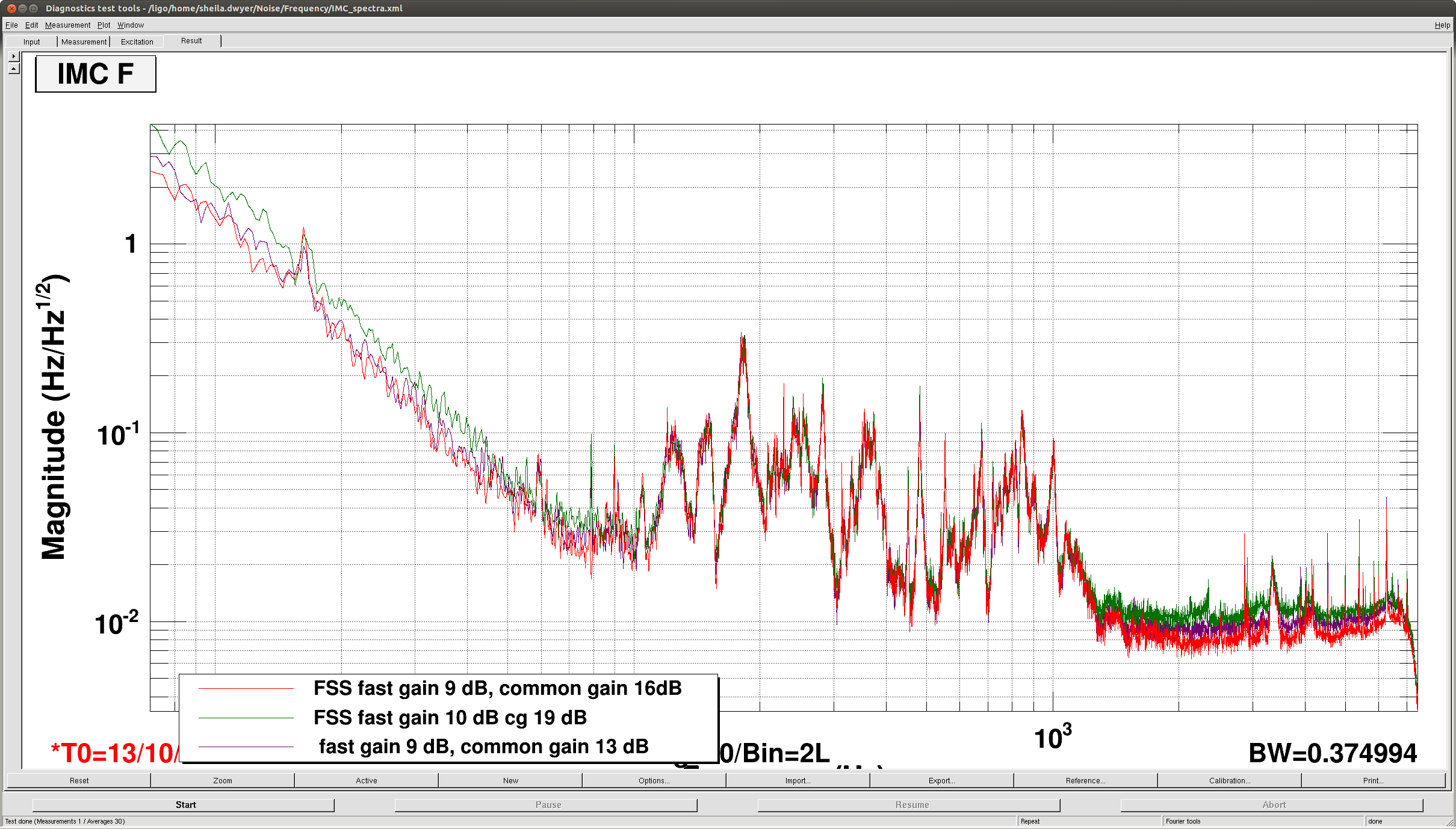
The gain at 1kHz from the IMC should be ~50 (ugf at 50 kHz) * 20 (boost) / 2 (mismatch between filter/cavity pole) ~ 500.
If the IMC gain is near 70 KHz one can probably kick in the second boost.
The noise level at high frequencies is 20 mHz/rtHz. Assuming this is the IMC shot noise at 2W, It would be at 4 mHz/rtHz at 50W. The VCO noise is around 2 mHz/rtHz at 1kHz. What we see is more like 8 mHz/rtHz, about twice higher than expected. Reference cavity?
The noise floor seen in IMCF with only the mode cleaner locked does not seem to be IMC diode shot noise, since it doesn't change as the input power is increased.