I wanted to find out how much contrast defect light we have in DARM at the moment. It seems to be about 2.0(5) mA at the moment. Since we run with 20 mA of total photocurrent, this implies a homodyne angle that is mistuned by about 6° away from the nominal value of 90°. I did not check how stable it is over the course of several hours.
To measure the contrast defect, I watched the height of 332 Hz pcal line in DARM while varying the dc offset.


Also, I found that the DARM residual is microseism-dominated at 50 W of input power (the current blrms is about 0.5 µm/s). So I turned on a boost in FM6 of LSC-OMC_DC. We should incorporate this into the DARM filter modules.
Expanding more on Evan's methods here:
Optical gain values in [mA/pm] were obtained by taking the magnitude of the transfer function at 331.9 [Hz] between H1:CAL-PCALY_RX_PD_OUT_DQ (pre-calibrated into [m] / zpk([],[1,1],1)) and H1:OMC-DCPD_SUM_OUT_DQ (pre-calibrated into [mA] to ~10% accuracy).
Total light on the OMC DCPD values in [mA] were pulled directly from H1:OMC-DCPD_SUM_OUT_DQ (again, pre-calibrated into [mA]).
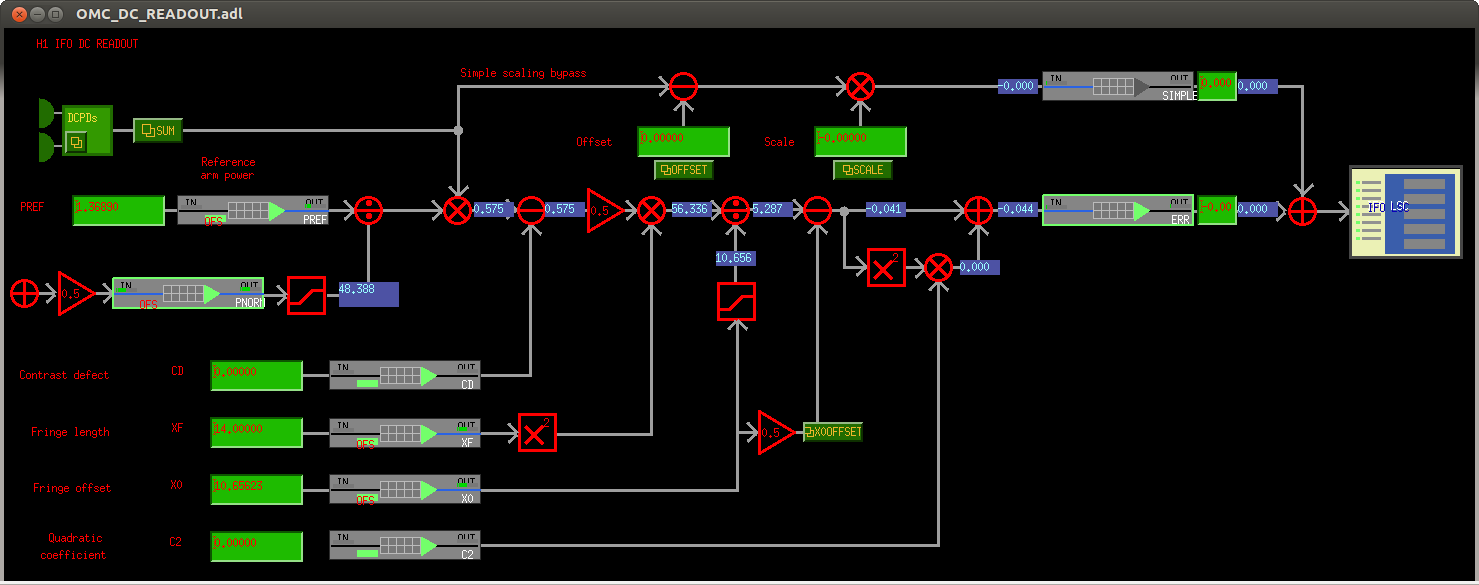
The DARM DC offset was varied by adjusting the "fringe offset" or H1:OMC-READOUT_X0_OFFSET (pre-calibrated into [pm] to ~20-30% accuracy). This EPICs record can be found on the "IFO DC READOUT" sub-screen (called OMC_DC_READOUT.adl) of the OMC_CONTROL.adl overview screen. The nominal value is 10.65623 [pm], and to obtain the above data Evan varied the DARM DC offset from 6 to 13 in 1 [pm] increments.
zeta = homodyne angle [rad] = arccot( contrast defect [mA] / total light on DCPDs [mA] )
where the contrast defect [mA] is the y intercept of the parabola.
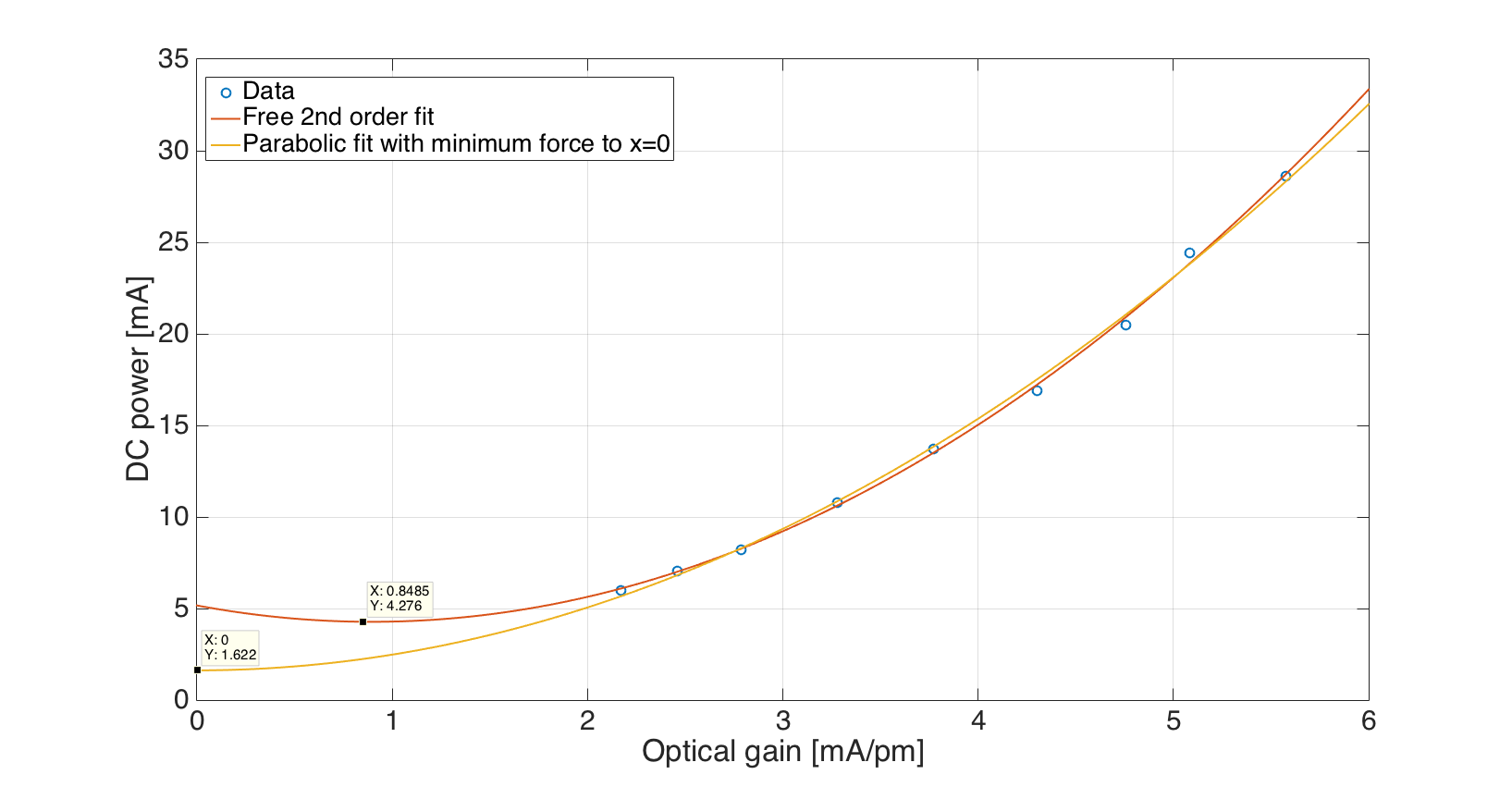
The subsequent IFO optical gain vs. DC power on the DCPDs was then fit (by-eye) to blind/simple quadratic function with a DC offset. to arrive at the answer.
From Evan's presentation G1601599, which nicely distills the famous-yet-cryptic 2001 Buonnano&Chen paper, the response of a DRFPMI interoferometer using detuned resonant sideband extraction can be parametrized into a pair of complex poles (for the optical spring, at frequency |p| and quality factor Q), a pair of real poles (for the coupled cavity, or "RSE" pole, at frequency xi) and zero, at frequency z, which can potentially (and typically does for low detuning) cancel one of the RSE poles:
dP 1 + i f / z
-- = g * --------------------------------------- (5)
dL (1 + if/|p|Q + (f/|p|)^2) - (xi / f)^2
The zero, in his presentation, is composed of the following fundamental parameters,
cos(phi + zeta) - r_s cos(phi - zeta)
z = f_a * ------------------------------------------ (8)
cos(phi + zeta) + r_s cos(phi - zeta)
where f_a is the arm cavity pole frequency (assumed to be the same for both arms), phi is the SRC detuning phase, and zeta is the homedyne angle.
One of the outputs of the above measurement, is that, if the homodyne angle, zeta, is consistently 90 +/- 6 [deg], then we can used Eq. (8) to simply fix the zero frequency in the overall IFO response (5), assuming the arm cavity pole frequency and SRC detuning phase also remain constant. This would reduce the parameter space over which the calibration group would have to MCMC in fits to measurements of the overall response (e.g. LHO aLOG 28302).
However,
(1) This is, again, *one* measurement of the homodyne angle, zeta. We're going to have to measure it multiple times, and quantify the uncertainty in the estimate better, to make sure that we're confident it stays there.
(2) The SRC detuning phase, phi, and the arm cavity pole frequency, f_a, also need measuring with quantifiable uncertainty. These are also parameters believed to be fixed, but the question is always to what level. f_a has been measured before to be ~83 Hz, using several techniques (e.g. LHO aLOG 7054), but rarely with quantified uncertainty. Further, those measurements are typically taken of a single cavity, and there is worry that the pole frequency may change a bit in the full IFO due to different spot centering*. The detuning phase "can be determined by the spring frequency."
To me, this is quickly going down a rabbit hole of another independent MCMC parameter estimation fitting regime, but I'm still quite ignorant on the topic.
*word on the street is that LLO has a technique, once in full lock, of "kicking the SRM fast enough" such that full IFO remains locked but simple as an PRFPMI. I couldn't find an aLOG on it, and these discussions with Evan today were the first I'd heard of it.
Worth exploring!
Doing a real least square fit gives different results, depending on what you assume
- If we require the minimum of the curve to be at z=0 (meaning that we have a good calibration of the optical gain zero), give a contrast defect of 1.6 mA. Sum of residuals is 1.3 mA^2
- If we allow the most generic second order polynomial, the fit is better (sum of residuals is 0.68 mA^2), but the minimum is at optical gain equal to 0.8 mA/pm and the contract defect is larger, 4.3 mA