Sheila, Jenne, Daniel
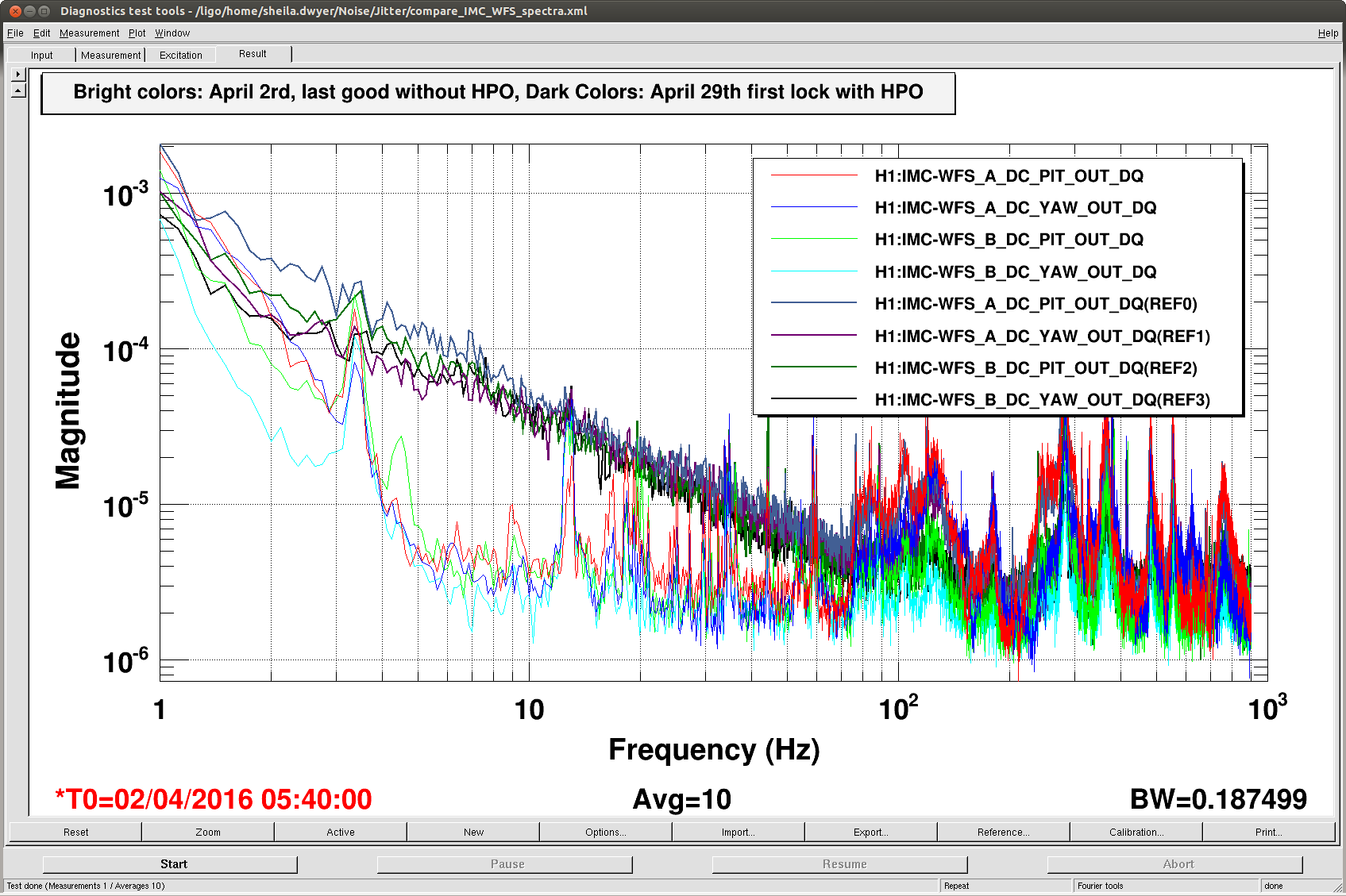
- The beam jitter seen by the IMC WFS became worse below 100 Hz as soon as the HPO was turned on, and has stayed similar since. The jitter at 100 Hz isn't much worse than it used to be.
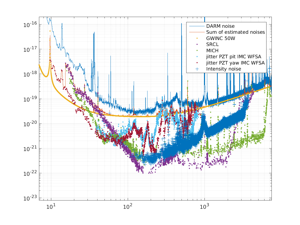
- Today Jenne and I redid a few white noise injections for MICH, SRCL, and jitter from the IMC PZT. The aux loop noise seems to be low enough that it is not our main problem.
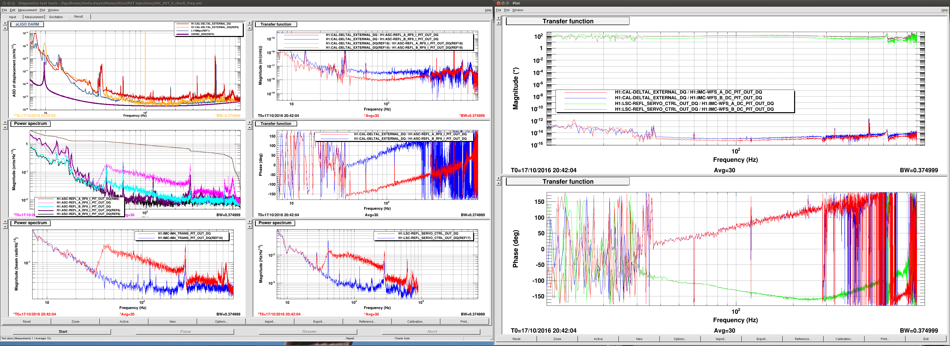
- We don't think that the main coupling of HPO jitter noise to DARM is through lock point errors on the refl diode.
More about the jitter measurements:
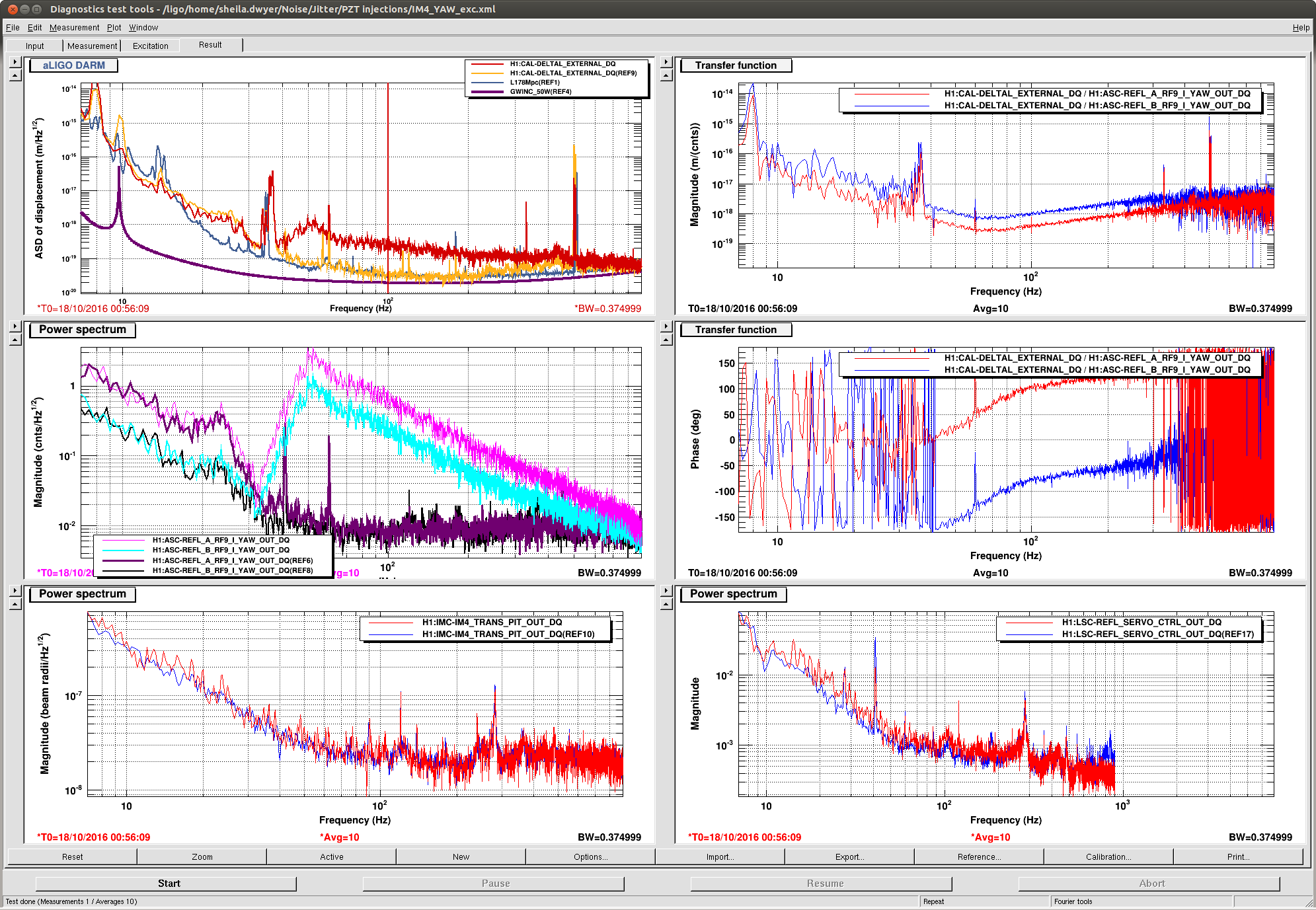
Jenne, Daniel and I made two types of jitter measurements this afternoon, first exciting the IMC PZT and making a projection using IMC WFS DC, then exciting IM4 and making projections using REFL WFS. The jitter measurements in the attached noise budget are based on the IMC PZT measurements, the IM4 ones are not included, because we don't believe that the REFL WFS noise floor is jitter, so these measurements were more like upper limits. The HPO jitter is in a gouy phase more similar to the one we excited using IM4 we believe, while the PZT excitations are in a gouy phase more simliar to the peaks from structures on the PSL table.
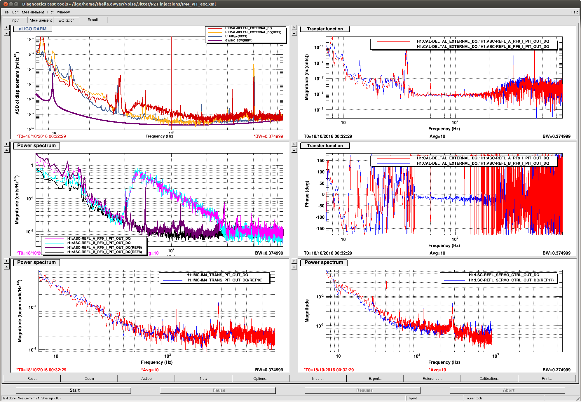
For both types of measurements, we wanted to see if it is plausible that the coupling mechanism to DARM is through the REFL diode. To do this we measured transfer functions to both the REFL control signal and to DARM. When we are exciting the IMC PZT, we cause sensor noise in the IMC loop which gets supressed by the CARM loop, so measuring the coupling to DARM CONTROL and multiplying by the previously measured REFL control to DARM coupling causes us to overestimate the coupling to DARM. For the IM4 excitation, we injected a line at 150 Hz, because we had to make a rather large injection in DARM to see it in REFL control. Using the REFL control signal to estimate the coupling to DARM we underestimate the coupling by about a factor of 5. This means that at least in the gouy phase that we excite with IM4 (which we think is similiar to the gouy phase where the broadband HPO jitter shows up), the main coupling of jitter noise to DARM is not through lock point errors on the REFL diode.