1. Noise
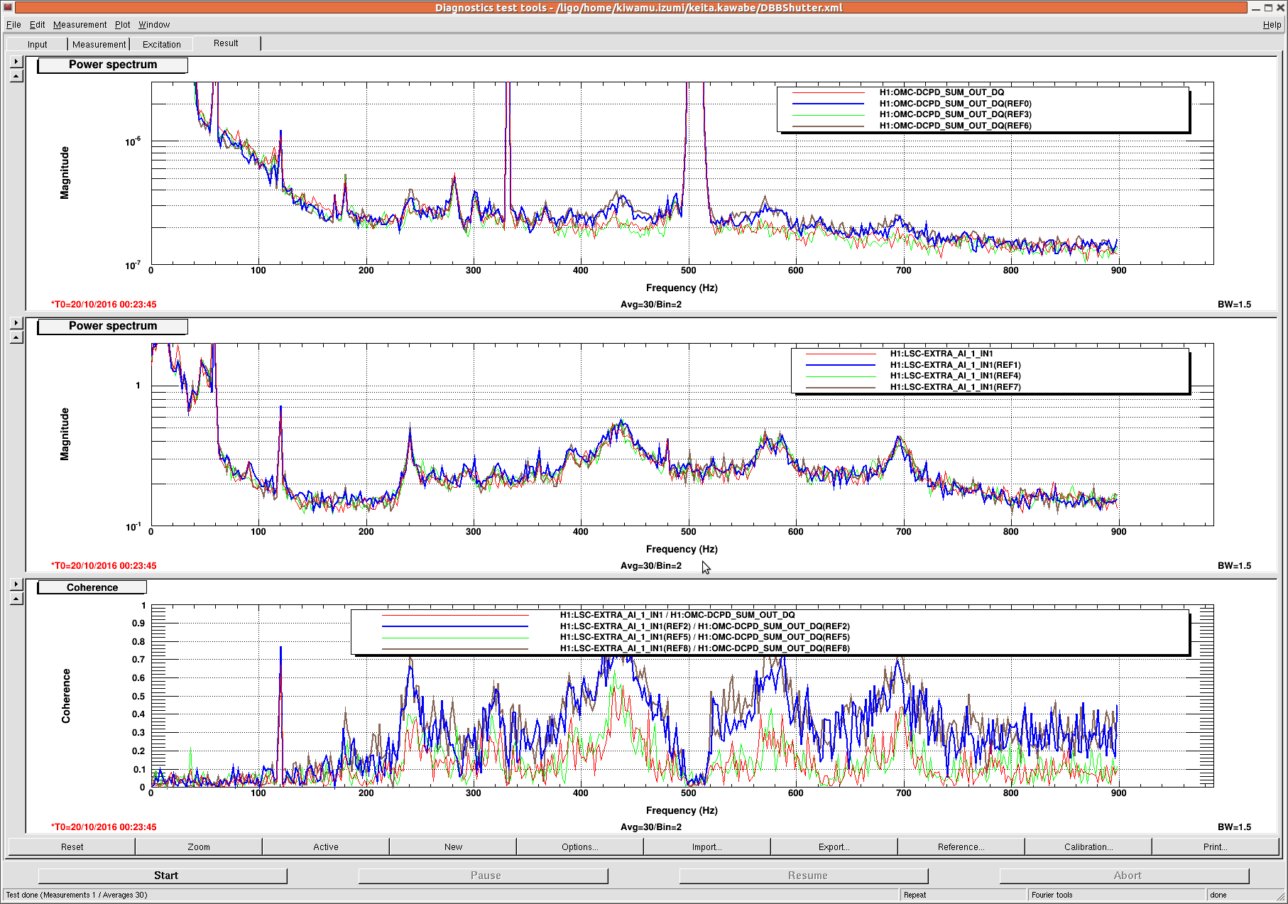
When DBB HPO shutter was closed, DARM noise decreased. I did open/close/open/close and this was quite repeatable (first attachment, red/green are shutter closed, blue/brown are open). Some of the jitter-ish peaks subsided and the DARM looked much smoother when the shutter was closed.
These days DBB shutter is open most of the time (it seems to have been in local mode most of the time for jitter FF). Now we're in half-working remote mode where the MEDM screen says "local" all the time but we can close/open the shutter by pressing buttons.
This should be some kind of scattering problem, e.g. optical feedback into HPO and/or even to the frontend.
Inside DBB the reflection from DBBPMC is received by photo diodes, there's one transmission received by CCD camera but the DBBPMC was not resonant. There's a thing called "TFP low power attenuator" that seem to attenuate the power going into DBBPMC, which is between DBB breadboard and the DBB HPO shutter.
Anyway, I wonder how many other significant scattering sources are there on the PSL table. There are other TFP low power attenuators as well as thermal type power meters which might receive some non-negligible power. I don't know which one is essential, but non-essential ones I'd like to temporarily block using black glasses.
2. Power
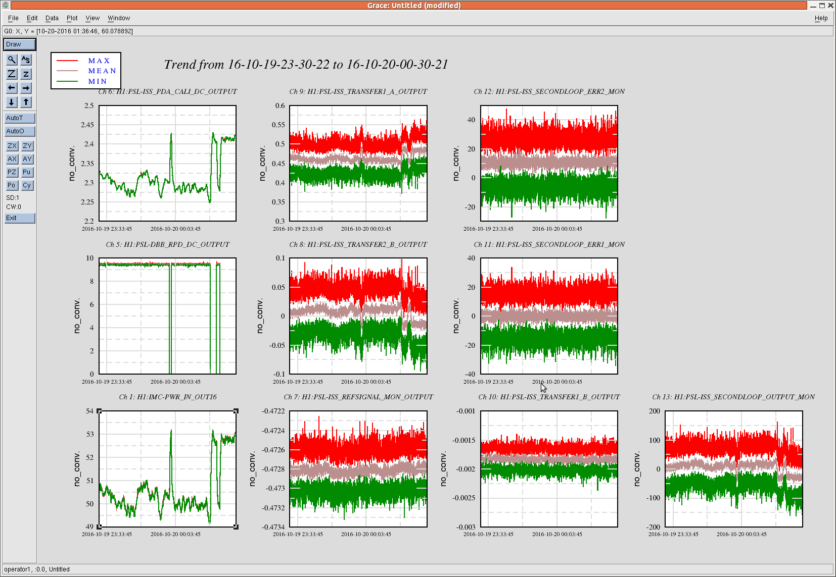
Stupid thing about this excercize was that the PSL power increased by about 3W when closing the DBB shutter (second attachment, left bottom is PSL power, left mid is the light the DBB REFL diode receives).
Even if you think the scatter causes some problem to the intensity, it should be taken care of by ISS.
It turns out that this doesn't have anything to do with the scatter, it's probably shoddy electronics (design or implementation).
The 1st loop PD actually changes even though the 1st loop is DC-coupled. REF signal is not changing. TRANSFER1_A is just the DCPD scaled and reference voltage added, i.e. PDA_CALI_DC/5+REF.
The "error signal" of the 1st loop is actually TRANSFER1_B (CH10), which is the sum of TRANSFER1_A and TRANSFER2_B.
TRANSFER2_B is the second loop output measured by the 1st loop board, and this should be proportional to the secondloop output measured by the second loop board (CH13). But the second loop was AC-coupled during this measurement.
If you look at all these signals, it's clear that the analog signal downstream of the second loop AC coupling point is pulled by a tiny amount by opening/closing of the DBB shutter (because of the current the driver has to supply?), amplified by the boost stage of the second loop, injected into the first loop, and the first loop dutifully responded by changing the power.
This is not a huge deal as far as we always close the shutter but it's disappointing.