I got suspicious about PMC length locking offset and changed H1:PSL-PMC_INOFFSET.
Increasing it by 1.7mV decreased the PMC length feedback by about a factor of 2, and 1st loop out of loop sensor by a factor of 4 or so, which doesn't make sense. In the attached, red and green are with nominal 3.1mV offset, blue and brown are with 4.8mV.
(After this measurement I noticed that Daniel increased the length gain from 16 to 28dB and forgot to bring it back. This measurement is with 28dB locking gain, but it still doesn't make sense.)
What's the nominal signal level for PMC demod? Is it tiny? When is the last time the PMC demod phase was optimized?
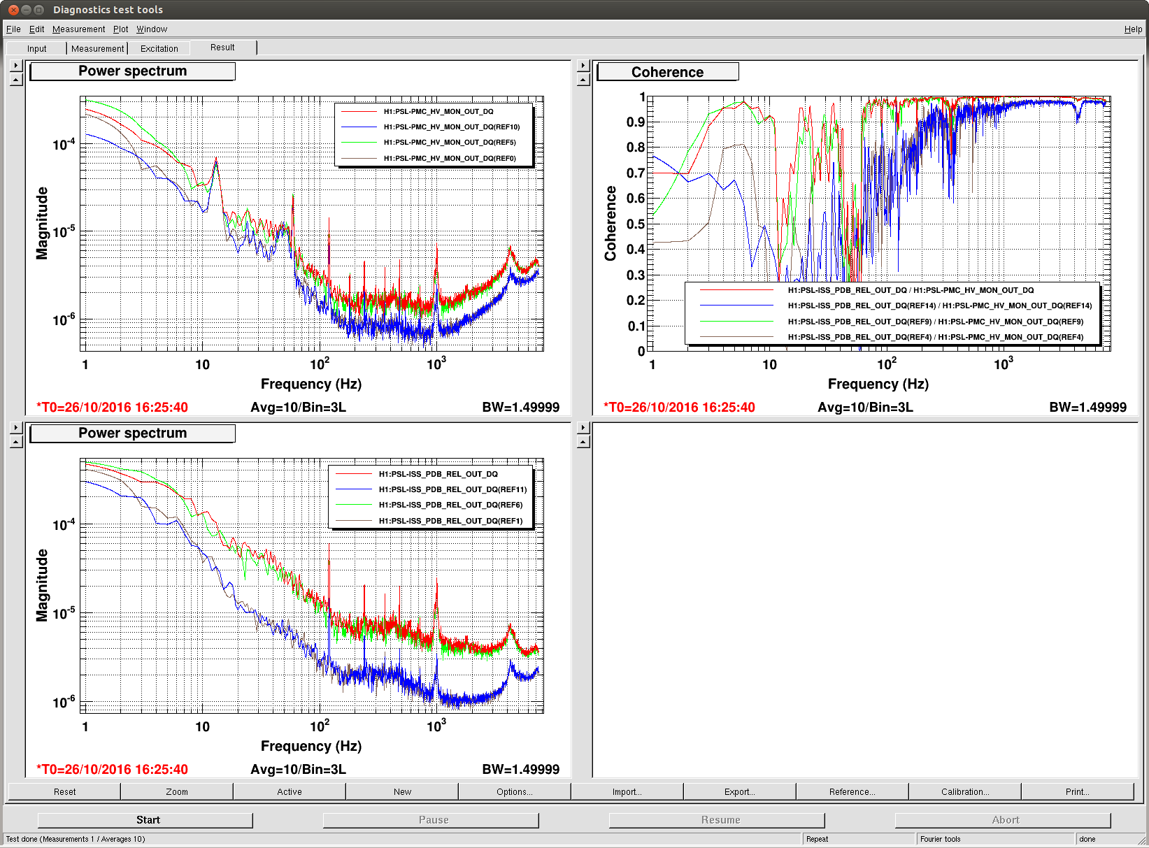
More strange stuff, when we look at the PDA and PDB photodetectors of the first loop in the ISS. In the attached plot, the current traces are with a PMC offset of 3.28mV, reference traces 1-15 are with a 3.58mV offset and reference traces 16-19 are with a 2.98mV offset. With a positive offset change we see a some degradation in PDA at high frequencies, whereas PDB sees significantly less noise. For a negative offset PDA gets a tad bit better and PDB gets worse. Overall PDB shows up to an order of magnitude change in its noise level, whereas PDA only shows up to a factor of 2, going the opposite way. The PMC gain was high and 28dB.

Here is the throughput as function of the offset with a Lorentzian as a fit. The parameters are 0.761, 3.28mV and 4.59mV for the amplitude, offset and HWHM, respectively. Looks like the demodulated signal is only ~9mV pk-pk.
(Keita writing as Sheila)
For those of you who are interested, Daniel's measurement doesn't mean that the noise behavior (in length locking and in intensity noise) makes sense.
(Now writing as myself.)
According to T0900577 (select ilspmc_servo3.pdf) the output of TUF-3 mixer is amplified by a DC gain of 4 and sent to a summation amplifier that has a gain of 10 for the demod and a gain of 1/100 for the offset.
The offset signal seems to be calibrated to represent the offset in the OUTPUT of the summation amplifier (i.e. +-100mV when the offset from DAC is +-10V). Update: I was deceived by HOPR and LOPR of he signal on MEDM being 100 and -100, but the calibration filter of this channel of this gain is just 3.2k, so the number should represent the equivalent offset after the gain of 4 but before the gain of 10.
So this 9mVpp is after the gain of 40 total, the demod right after the mixer should be ~9mV/4/10=230uVpp.
Update: The demod right after the mixer should be ~9mV/4=2.3mVpp.
If this is true this is excessively small and cannot be good, and I wonder if the demod phase is correct or if this is an expected signal level. If this is as designed, can't we increase the modulation depth upstream or something?
(The main document in the above DCC is so-called PDF Portfolio, which is just a document containing all pdfs listed in "other files". If you're on Linux workstations the pdf in the above DCC appears as if it's just a one-page document promoting Adobe product, but if you're using evince document viewer, change "thumbnails" on the left panel to "attachments", and you can select whichever file in the portfolio to view).
Looking at the RF chain:
- The output of the RF amp in the CER is 13 dBm
- There is a 2 dB attenuator in the CER
- Assuming 1 dB cable loss
- There is a 20 dB attenuator at the PSL rack panel
Therefore, the drive to the modulator seems to be -10 dBm, or 71 mV rms. A standard New Focus 4004 EOM has a modulation coefficient of 25 mrad/V. So the estimated modulation depth is around 1 mrad.
The mixer readbacks are flawed and just see ADC noise. They could use a gain of 200 to get above the ADC noise. Proposed values:
- N7: OP27
- R33: 1K
- R11: 200K
- R12: 0
- C4: 33p
- J2: remove