jeffrey.kissel@LIGO.ORG - posted 16:23, Monday 21 November 2016 - last comment - 17:06, Monday 21 November 2016(31693)
CAL-CS Front-End (and therefore GDS Low-Latency) DARM/DELTAL_EXTERNAL Time-Independent Calibration Updated for O2
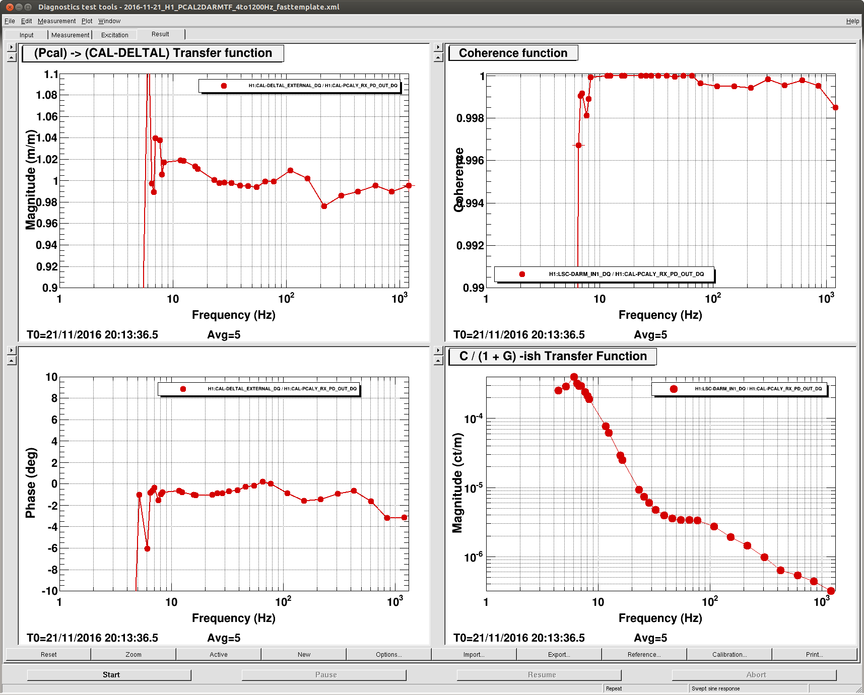
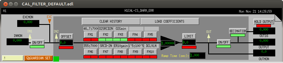
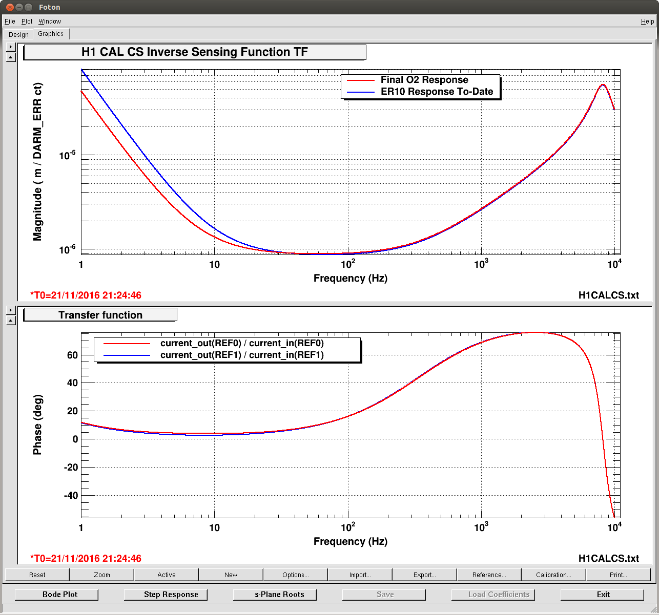
J. Kissel, D. Tuyenbayev, K. Izumi, E. Goetz, C. Cahillane

We have successfully updated the calibration in the front-end calibration. This means the static, frequency-dependent part of the low-latency calibration pipeline is ready to go for O2. Many thanks to all who've helped get this together in such short time.

Kiwamu has updated the actuation side: see LHO aLOG 31687
I have updated the sensing side: see this aLOG below.
Darkhan has updated the EPICs records that store the model at calibration line frequencies: see LHO aLOG 31696
These changes have been accepted in the CAL-CS SDF system.

I always hate saying this statement because it comes without an uncertainty estimate and boils down a time-dependent, frequency dependent answer to a pair of numbers -- and DELTAL_EXTERNAL is limited by the accuracy of the front-end -- but I know people like to hear it, and it's a good, simple benchmark to hit:
The resulting agreement between mean values of a swept-sine transfer function between the low-latency pipeline output, CAL-DELTAL_EXTERNAL and PCAL is roughly 2% and 2 [deg] for almost all frequency points between 10 Hz and 1.2 kHz.

I was minutes away from finishing a broad-band PCAL injection so we can compare the output with the GDS pipeline to get the full answer, when the 6.9 [mag] Japanese EQ hit (see LHO aLOG 31694). We'll get this during the next lock stretch.


We will be working on the uncertainty budget of the next coming days (but expect us to take a Thanksgiving break). We expect the time-independent, statisical uncertainty to improve beyond that of O1 but because they haven't happened yet, we can't make claims about the systematic errors that arise from uncorrected for time-dependence. This is especially true if the evidence for a changing SRC detuning spring frequency holds (see discussion in LHO aLOGs 31665 and 31667).

%%%%%%%%%%%%%%%
Details:
%%%%%%%%%%%%%%%
Actuation Function
Again, see Kiwamu's aLOG for details on the updates to the actuation function: LHO aLOG 31687.

Sensing Function
I've updated the front-end's inverse sensing function to the parameters that are now used as the O2 reference measurements:
                                 [Units]  value(95% c.i.)
Meas Date                 2016            Nov 12
IFO Input Power                  [W]      29.5
SRC1 Loop Status                          ON

Optical Gain              x 1e6  [ct/m]   1.153 (0.003)   => Inv. Optical Gain = 8.673e-7 (2.255e-09) [m/ct]
DARM/RSE Cav. Pole Freq.         [Hz]     346.7 (4.1)
Detuned SRC Optical Spring Freq. [Hz]     7.389 (0.3)
Optical Spring Q-Factor (1/Q)    []       0.0454 (0.01)   => Q = 22.015 (4.84)
Residual Time Delay              [us]     2.3  (3.4)      => consistent w/ zero, so not included

aLOG                                      LHO 31433

The front-end implementation in foton is as follows:
    Bank: H1:CAL-CS_DARM_ERR
        Module  Name           Design String
        FM2     O2SRD2N        zpk([346.7;7.2231;-7.5587],[0.1;0.1;7000],1,"n")gain(5458.55)
        FM3     O2Gain         gain(8.673e-7)
The bank is screen captured and attached, just in case SDF dies.

Explanation for each component in the FM2 / O2SRCD2N filter:
    - 346.7 Hz zero is the inverse of the darm coupled cavity pole, as fit in LHO aLOG 31433.
    - 7.2231 and -7.5587 Hz zeros represent in inverse of the detuned optical spring. Because of the limitations of foton and the need for anti-spring-like response, we must convert the two positive zero frequencies and Q into a positive and negative zero (i.e. one in the real, one in the imaginary plane):

                f^2                (2*pi*i)^2               f^2
    ---------------------------- =  ---------- * ---------------------------
    f^2 - i*(f*f_s/Q) + (f_s)^2    (2*pi*i)^2    f^2 - i (f*f_s/Q) + (f_s)^2

                                        (s = 2*pi*i*f  ; c_s = 2*pi*f_s)

                                             s^2
                                 = ------------------------
                                   s^2 + s*(c_s)/Q - (c_s)^2
          Zeros are the roots of
                            >> 0 = s^2 + s*(c_s)/Q - (c_s)^2

                                          1  (    (c_s)          { ( (c_s) )^2                     }
                            >> s_{+/-} = --- ( -  ----- +/- sqrt { ( ----- )   - 4 (1) (- (c_s)^2) }
                                          2  (      Q            { (   Q   )                       }

                                          1  (   2*pi*f_s          { ( 2*pi*f_s )^2                 }
                            >> f_{+/-} = ----(-  -------- +/- sqrt { ( -------- )   + 4(2*pi*f_s)^2 }
                                         4*pi(      Q              { (    Q     )                   }

                                         f_s
                            >> f_{+/-} = --- ( -1 +/- sqrt { 1 + 4 Q^2 } )
                                         2 Q
      For f_s = 7.389 Hz and Q = 22.015, that means the positive and negative zeros are at 7.2231;-7.5587 Hz, as shown in the design string.
    - The poles at [0.1;0.1;7000] are to artificially roll off the inverse response -- these are the same as they were in ER9. Remember the 7000 Hz pole distorts the response enough that this needs to be corrected for in the GDS pipeline.

This CAL-CS design is not perfect. I've exported the design back into matlab and compared it against the model using
      /ligo/svncommon/CalSVN/aligocalibration/trunk/Runs/ER10/H1/Scripts/CALCS/compare_model_v_CALCS_sensing.m

and I attach the discrepancy. The discrepancy at high-frequency should be the same, since we've used the 7000 Hz pole to roll off the darm coupled cavity zero as in O1. The low frequency could use some correction. The DARM UGF is now around 65 Hz, where this sensing function discrepancy starts to matter. There, the phase discrepancy is 0.52 [deg] @ 65 Hz, and works its way up to 3.6 [deg] at 10 Hz. Thus, we don't expect too much impact at all, but it needs to be quantified. I'll discuss with the GDS team to see if such a correction filter is worth it or possible.

All of the above actuation and sensing function parameters have been built into the matlab DARM loop model. From here on out, we'll be using the relative, time-dependent correction to make corrections to the model such that they match any new measurements.
Images attached to this report
Non-image files attached to this report


Comments related to this report
Nicely done Team Calibration!