Using ~1/2 of the ITMY pitch bias range, the green beam gets back to the ETMY.
After enabling the ITMY HEPI + ISI, I scanned the ITMY bias sliders and looked at the ETMY face camera. The ITMY EUL2OSEM matrix has gains of ~5-10 (unlike the TMSY ?) and so the +/-15000 cts of the slider screen is enough to go full scale...and consequently, I tripped the watchdogs a couple times.
The yaw alignment was really good - the return beam to the ETM was nearly centered horizontally, but needed ~1/2 of the ful pitch range of the ITMY TOP stage.
With the illuminator off, it was easy to see the beam flashing around after the watchdog tripped. With the illuminator ON, but turned down to 0.5 Amps, I could see the stuff in the chamber as well as the green beam. Then I used the usual method of putting the beam on the 4 compass points of the ETMY cage and centering it on the mirror by averaging.
Moving the yaw slider to the right moves the beam on the cage to the right. Moving the pitch slider to the right moves the beam down. It takes +1000 slider units of torque to move the beam from top to bottom of ETMY.
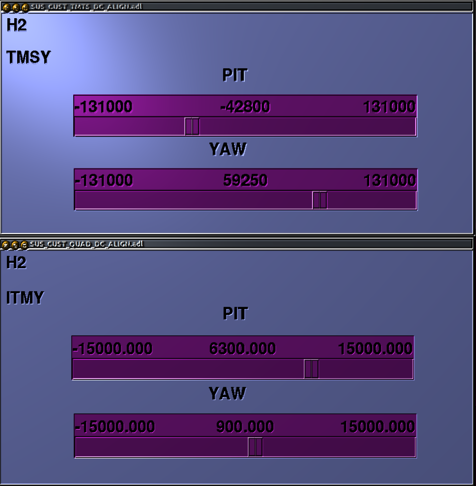
The values of ITMY bias that center the beam on ETMY are P = +6300 & Y = +900.
So the ITMY alignment was off by ~6 mirror diameters => (0.210 m / 4000 m) / 2 = 25 micro radians.
Now that the beam goes both ways, the next thing to do is to align the ETMY to center the beam on ITMY using the baffle PDs as before. Then perhaps we'll be able to hear the cavity flashes if we can route the audio from the baffle PDs or the ALS green PDs into the control room.
And...lots of YAW bias gets the ETMY aligned to get the beam back on to the ITMY baffle PDs. The ETMY bias for rough alignment is:
P = -2700
Y = +14200
I haven't seen any flashing yet that looks like a Fabry-Perot resonance, but at least all of the suspensions are close enough in alignment to proceed. Since the TMSY and ETMY both have large yaw biases, we can still hope that they can be mostly relieved by yawing the HEPI (assuming they need the same direction of yaw). Because of the double-loop nature of the quads, we should also get some ITMY pitch relief from pitching its HEPI.
From the flashing that can be seen from the ITMY spool cam, it seems like the return green beam is hitting the ITMY baffle at the edge around the mirror, at the 2 o'clock position look at the ITM from the spool.
While trying to get the video rerouted to the control room as well as EY I will look at hooking up a FiBox to the green light signal. Will talk to Keita about this.
There is something funny about the numbers here. The claim is that the ITM alignment was off by about 25 micro-radians, and that correcting this uses about 1/2 of the pitch control range (I assume this is at the TOP stage). However, according to T1100595-v1, the control range of the quad, from the TOP stage, is 1.14 mrad in pitch; it is a little unclear as to whether this is +/- 1.14 mrad or a 1.14 mrad total swing; either way, it is much larger than 25 urad -- it should take less than 1/10 of the range to correct it.
I think its funny too. Using ~50000 cts (as measured at the DAC outputs for the face OSEMs on TOP) seems like its close to the 217 limit for the DAC.
Should have checked the coil driver readbacks to find out how much current/voltage was being used to make sure there is no attenuation happening downstream.
Jeff K and I found the basic problem with the ITMY alignment numbers. There is a factor of 10 error in the observed pitch misalignment number. The 0.21 m above should be 2.1 m (6 * 0.34 m). The pitch offset is thus 250 micro-radians. We also noted that there seems to be a factor of 2 discrepancy between the designed input range for the TOP driver and the DAC output range, so that we can only access half the current range for each BOSEM: the TOP driver was designed to give +/- 200 ma for each coil, but we can only go to +/- 100 ma. So, the 250 micro-rad of offset is about half the pitch bias range we have available, which is about half of what we should have.
P. Fritschel, J. Kissel

The confusion lies in Rana's calculation of the total distance for beam travel:
1000 cts of torque = beam moves top to bottom of ETMY
the ETMY is 34cm in diameter.
So, a 6300 cts offset, is
6300 [ct]* 34/1000 [cm/ct] = 214 [cm] = 2.14 [m]
not ~0.210 [m] as Rana uses in his calculation (i.e. he's off by a factor of 10). So, correcting the number in his calculation, we get

pitch offset = torque [ct] / (2 L) % factor of two from "optical lever" effect see G1200698
             = (2.14 m / 4000 m) / 2
             = 250 micro radians.


This jives with the predicted range of the QUAD TOP driver and the current monitors:

Predicted Range
T0900232 says, in section 6.1:
"As the input voltage is specified as 10V* and the voltage gain of the circuit is 1.2** the voltage swing of each output terminal is +/-12[V]. As each output resistor is 40 Ohms, and the [B]OSEM coil resistance is 40 Ohms, the total output resistance is
     (40 [Ohms] + 40 [Ohms] + 40 [Ohms]) = 120 [Ohms].
The voltage across this resistance will be 24[V] maximim, so the [maxmimum] current will be
     24 [V] / 120 [V/A] = 200 [mA] "

However,
* I've confirmed via direct measurement that the 18-bit DACs can only do +/- 10 [V] differentially NOT per leg. So the max possible voltage is
     DAC_MaxV = 10 [V] (differential output)
** The DC gain of the circuit is
     CD_VoltageGain = (1+R3/R10) = 1.22 [Vin/Vout]
(OK, 2% error, but just wanted to make sure we understood from where Ron's numbers came)
And just in case, to remove all suspicion:
From the QUAD Top Driver board schematic, D0902747:
-      Rout = (R1+R5)*(R90+R91)/(R1+R5+R90+R91)
          = (22+22)*(220+220) / (22+22+220+220) [Ohms]
          = 40 [Ohms],
so that's correct, and Stuart just measured the BOSEMs to have a resistance of
-      Rcoil = 42.7 [Ohms] ,
so that's correct as well.

So, the maximum output current of the circuit is actually

     DAC_MaxV * CD_VoltageGain / (2*Rout+Rcoil) = 10 [V] * 1.22 [V/V] / (40+40+42.7) [V/A] = 0.09943 [A] = 99 [mA]

which if all other numbers from T1100595 are correct, then this would produce a maximum displacement of

Pitch: 560 micro rad
Yaw: 580 micro rad


Current Monitors
The current monitors have a calibration of

Amps across the BOSEM coil = ADC [V/ct] * Fast_I Mon Circuit Gain [V/V] / BOSEM Coil [V/A]
                           = 40/2^16 [V/ct] * 3/2 [(single ended Vout) / (differential Vin)] * / 42.7 [V/A]
                           = 2.1441e-05 [A/ct]

The current monitors for the primary Pitch OSEM (F1) on the ITM, with a 6400 [ct] torque offset from the sliders, show -2736 [ct] of current. (I use F1 and not either F2 or F3, because F2 and F3 also contain the Yaw offset). That means the current across the coil is

Icoil = 2736 [ct] * 2.1441e-05 [A/ct] = 0.059 [A] = 60 [mA]

which is indeed about half the range of the coil driver, which jives with both the [corrected] calculation of 250 urads and the observation that Rana saw ~50000 cts (or half the range of the 2^17 ct DAC max).


Note that the original design intent was to have ~1 mrad of range from the TOP stage, so if we want to restore that intent, we should reduce the output resistance of each leg by a factor of 4, such that the range is

DAC_Max * CD_VoltageGain / (2*Rout+Rcoil) = 10 [V] * 1.22 [V/V] / (10+10+42.7) [V/A] = 0.19458 [A] = 194 [mA]

which could be done by changing the values of R1, R5, R90, and R91 to 10 Ohm resistors.