evan.goetz@LIGO.ORG - posted 19:09, Tuesday 13 December 2016 - last comment - 11:24, Friday 16 December 2016(32542)
Some investigations needed
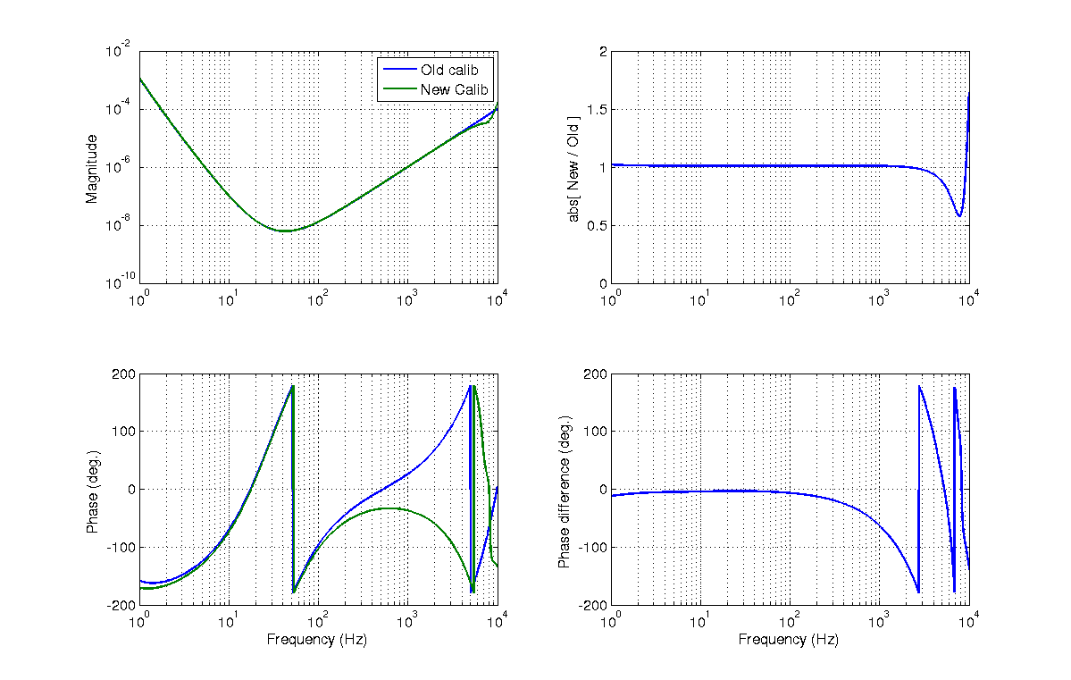
Looking at a few tasks on the calibration to-do list, I ended up down the rabbit hole. Sadly, it's getting late and will have to return to this tomorrow.

Investigations:

1) Working on fixing the PCAL --> CAL-CS_DELTAL_EXTERNAL calibration (see LHO alog 31994). Kiwamu's original script computed a transfer function accounting for time delays caused by the DAQ and the CAL-CS whitening filter. However, this is already taken into account in the clock cycles delay in the CAL-CS model when adding the sensing and actuation paths. Since CAL-CS corrects for the phase delay caused by AA/AI filtering--analog and digital--using the delayed actuation path, then what one really wants is to correct CAL-CS for the magnitude changes of the AA/AI filtering and any CAL-CS whitening on this channel while also correcting the PCAL_RX_PD channel for the effect of AA and that we also have not applied a filter with two poles at 1 Hz (for the free-mass response):

DELTAL_EXT   W * [Derr/C_foton + A*Dctrl*delay]
---------- = ----------------------------------
PCAL_RX_PD         m * f^2 * AA_a * AA_d

 m     DELTAL_EXT [C_real/C_foton] / [W * abs(AA_a * AA_d * uncompensatedOMCpoles)]
--- = ------------------------------------------------------------------------------
 m                PCAL_RX_PD / [f^2 * AA_a * AA_d]

Note that the correction factors applied in the numerator of the final equation are really only to be applied to the sensing side. However, the corrections are only at high frequency (low-frequency corrections are simply unity), so the numerator term is dominated by the sensing function.

Thus the calibration to be applied is thus:

   [C_real/C_foton] * [f^2 * AA_a * AA_d]
----------------------------------------------
[W * abs(AA_a * AA_d * uncompensatedOMCpoles)]

Unfortunately, this results in a large deviation in phase at higher frequencies (~60 degrees at 1 kHz, see attached figure) while recent measurements using an incorrect calibration filter do not suffer from this large phase deviation. The phase deviation is due to application of the analog and digital AA on the Pcal. Why?

2) I constructed an O2 version of the front-end calibration time delay diagrams based on the model (see attached), but when I look at the GDS correction factors to be applied to the CAL-CS channels, I do not find matching delays. In addition, the values obtained to not mesh with the recent work done at LLO (see LLO alog 29899). This will have to be investigated further tomorrow also.
Images attached to this report
Non-image files attached to this report

Comments related to this report
The AA (analog and digital) had to be taken into for DELTAL_EXT also, including their phase. And also we need a cycle advacne for DELTAL_EXT. Attached plot show the same comparison with the mentioned modifications and we see that the old correction factor was good to use. I have also attached the script used to make the plot. Most of these correction factors are calculated in computeSensing.m of DARM model code, so I just get these factors from there.
Images attached to this comment
Non-image files attached to this comment

Thanks to Shivaraj for pointing out the 7 clock cycles adjusted the actuation path to have consistent phase with the sensing path, but that a signal measured by back CAL-CS_DELTAL_EXTERNAL would have an apparent delay of 117.6 usec (see PDF attachment to original alog entry above) + 61 usec for the delay between OMC user model and CAL-CS user model. The apparent 117.6 usec on the sensing side is a combination of optical response, AA filtering, and uncompensated, super-Nyquist OMC DCPD poles.
The correct math is as follows:
DELTAL_EXT W * [Derr/C_foton + A*Dctrl*delay]
---------- = ----------------------------------
PCAL_RX_PD m * f^2 * AA_a * AA_d
m DELTAL_EXT * [C_foton/C_real] / [W * AA_a * AA_d * OMCpoles * OMCtoCALCSdelay * lightTimeDelay * unknownSensingDelay]
--- = -----------------------------------------------------------------------------------------------------------------------
m sign * PCAL_RX_PD / [f^2 * AA_a * AA_d]
So the calibration transfer function is:
[C_foton/C_real] * f^2
-------------------------------------------------------------------------------------------
[W * sign * uncompensatedOMCpoles * OMCtoCALCSdelay * lightTimeDelay * unknownSensingDelay]
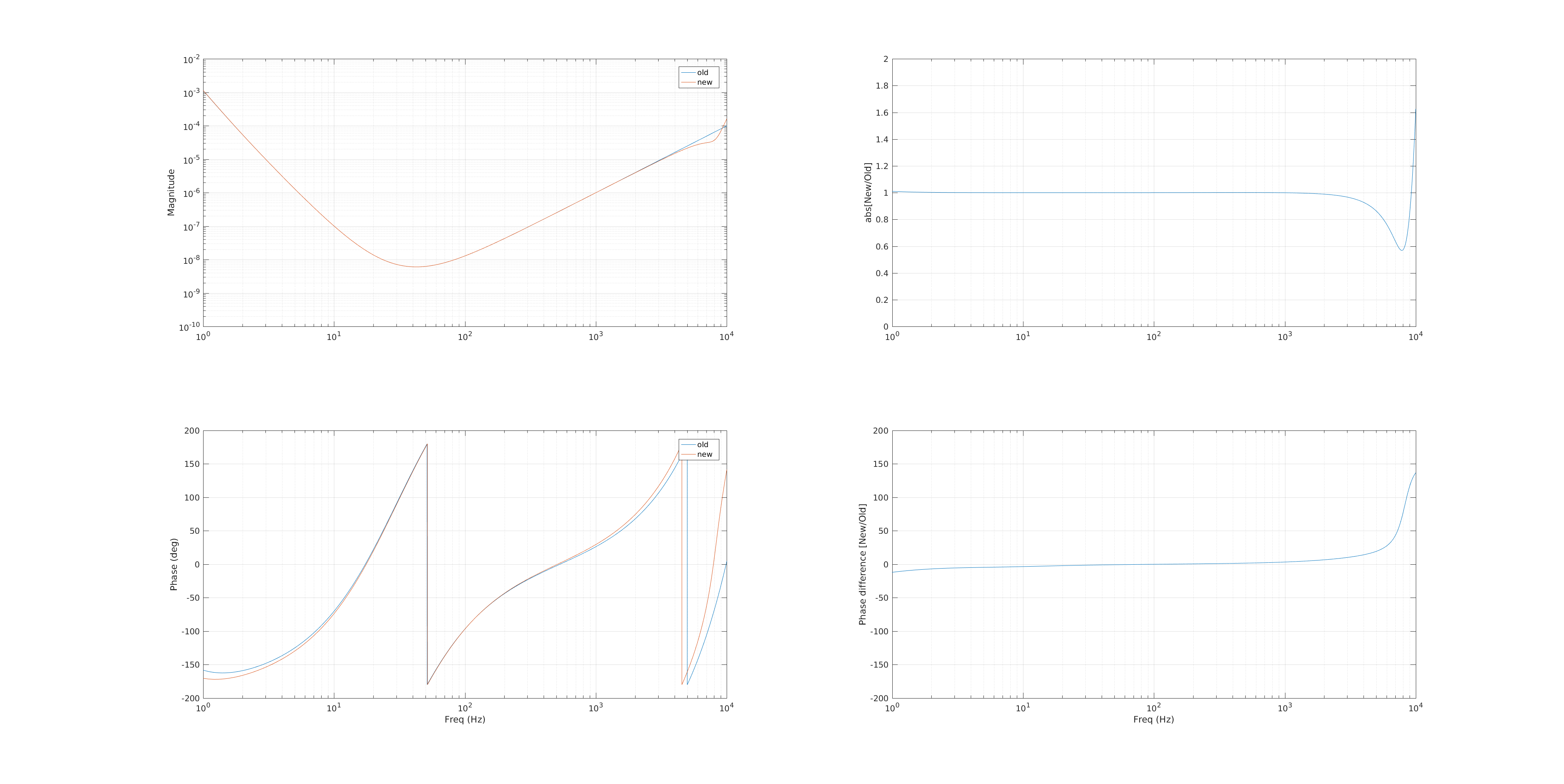
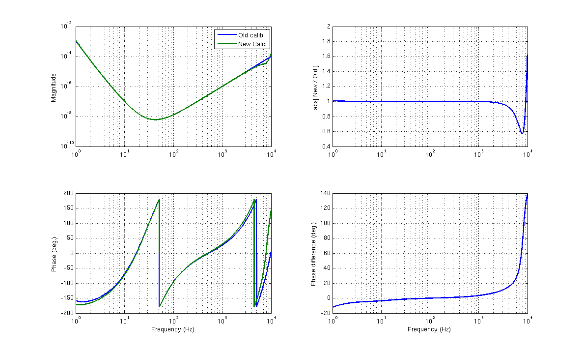
A comparison of the new transfer function is attached below. Note that the magnitude is basically unchanged, but there are changes in phase at the ~5 degree level or less from 10 Hz to 1 kHz. The new transfer function is stored at: /ligo/svncommon/CalSVN/aligocalibration/trunk/Runs/PreER10/H1/Scripts/ControlRoomCalib/pcal2darm_calib.txt.
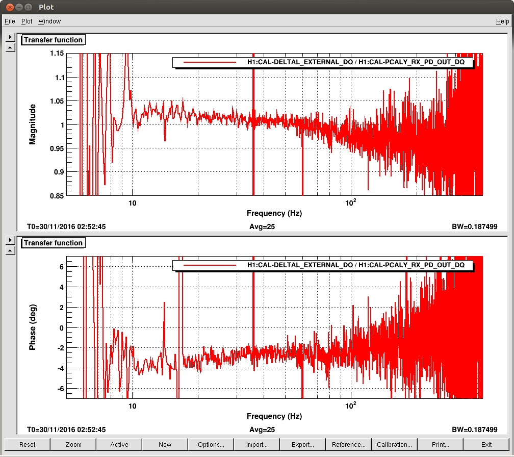
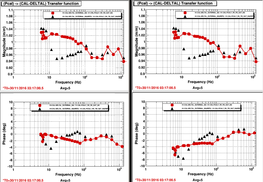
I also attach a comparison of DTT transfer functions using the old calibration versus the new calibration. The magnitude of the transfer function is basically unchanged. The phase is modestly affected. Unfortunately, since the transfer function wasn't perfect before and it remains imperfect (darn). I saved 2016-11-30_H1_PCAL2DARMTF_4to1200Hz_fasttemplate.xml with the new calibration transfer function.
Images attached to this comment
The broad-band calibration has also been updated. The transfer function is also created by the same script,
/ligo/svncommon/CalSVN/aligocalibration/trunk/Runs/PreER10/H1/Scripts/ControlRoomCalib/H1_pcal2darm_correction.m

The broad band transfer function is stored at: /ligo/svncommon/CalSVN/aligocalibration/trunk/Runs/PreER10/H1/Scripts/ControlRoomCalib/caldeltal_calib.txt

I have updated the most recent DTT session with this changed calibration (see attached): /ligo/svncommon/CalSVN/aligocalibration/trunk/Runs/ER10/H1/Measurements/PCAL/2016-11-30_H1_PCAL2DARMTF_BB_5to1000Hz.xml

Note that the DTT session calibrates the DELTAL_EXTERNAL and PCAL_RX_PD channels separately. The PCAL_RX_PD channel is calibrated by zpk([],[1;1],1,"n"); therefore, the DELTAL_EXTERNAL needs to have all the other calibration applied to it:

                           [C_foton/C_real]
-------------------------------------------------------------------------------------------
[W * sign * uncompensatedOMCpoles * OMCtoCALCSdelay * lightTimeDelay * unknownSensingDelay]
Images attached to this comment