jeffrey.kissel@LIGO.ORG - posted 17:17, Wednesday 21 December 2016 (32799)
PUM Driver Reverted; Detailed Comparison Between Temporary Swap and Now Reverted Driver; Suggest a 'Poor Calibration Flag' for the Observational Stretch
J. Kissel
Yesterday, after seeing little-to-no impact from replacing the H1 SUS ETMY PUM driver, we have reverted to the original driver.
- Spare Driver (s/n S1102648) swapped in: LHO aLOG 32745
- Original Driver (s/n S1102652) reverted in: LHO aLOG 32780
The only H1 observational stretch that includes this temporary PUM driver:
Dec 20 2016 10:44:28 UTC - Dec 20 2016 13:43:44 UTC
Dec 20 2016 02:44:28 PST - Dec 20 2016 05:43:44 PST
GPS 1166265885 - GPS 1166276641
Duration: 10756[sec] or 2.99 [hr]
During this time, L1 only had a short 22 minute lock stretch,
Dec 20 2016 12:31:15 UTC - Dec 20 2016 12:53:34 UTC
Dec 20 2016 04:31:15 PST - Dec 20 2016 04:53:34 PST
GPS 1166272292 - GPS 1166273631
Duration: 1336 [sec] or 0.37 [hr]
Note: While reverting the coil driver, Fil also power cycled the respective AI chassis, so observational stretches after Dec 20 2016 13:43:44 UTC, if they have an improved glitch rate, are likely due to either reseating / reconnecting the original PUM driver (s/n S1102652), or are perhaps more likely related to the power cycle of the AI chassis.
---------
Characterization Measurement Comparison between Temporary Spare Original (S1102648) and Original Driver (S1102652)
Using the same entirely digital measurement technique we used to determine the compensating poles and zeros for the coil drivers before O1 (i.e. using the coil driver monitor circuits; see LHO aLOG 20846), I measured the PUM driver's frequency response before and after we swapped out the driver for a spare. Results are attached.
The .png attachments focus on State 3, which is the state used in nominal low noise and therefore would affect calibration, coil balancing, and length-to-angle decoupling filters. The .pdf attachments cover all four states for all four coils that were measured (because we do transition between states during lock-acquisition -- important for duty cycle, not sensitivity).
The analysis process is as follows (in order of .png attachments):
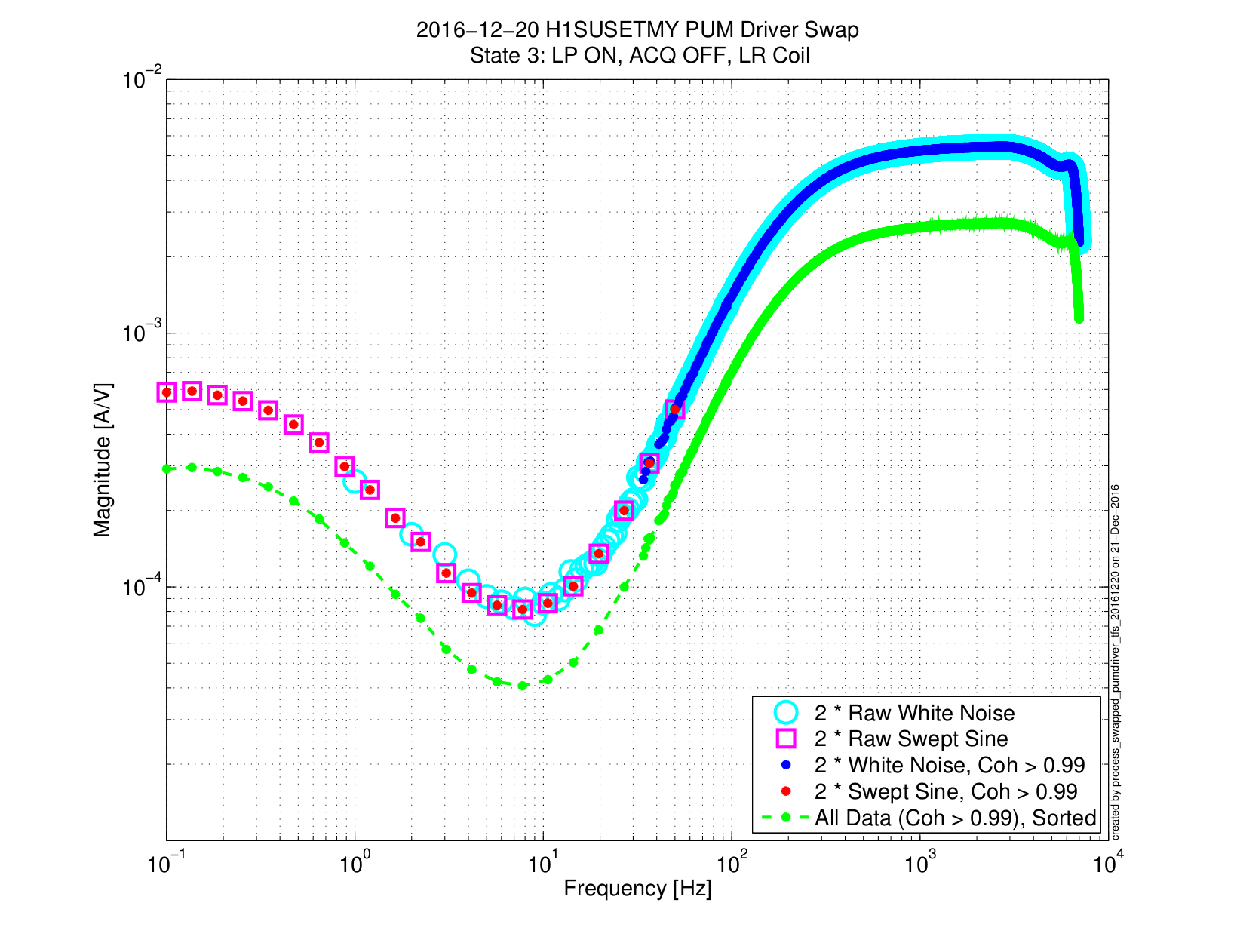
(1) In order to get coherence across the entire relevant frequency band**, I took both swept sine and white noise transfer functions. These were each filtered for high coherence (a threshold of 0.99), and then concatenated. The .png shows one coil (LR), in one state (state 3), for the original driver (S1102652) as an example to illustrate the process.
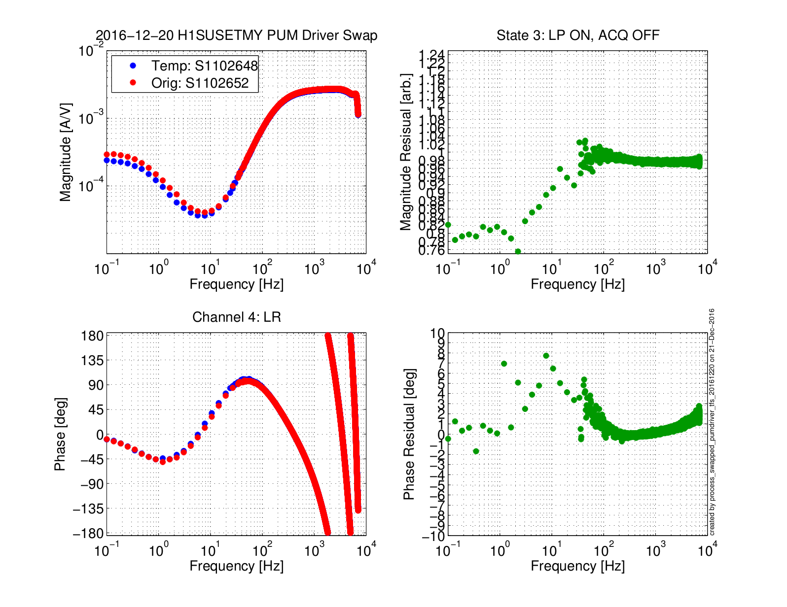
(2) Once this data is gathered and concatenated for the two drivers, for all 4 states of all 4 coils, I take the ratio of the original vs. the temporary driver. The .png shows an example of this again for the LR coil in state 3, but for both drivers and their ratio.
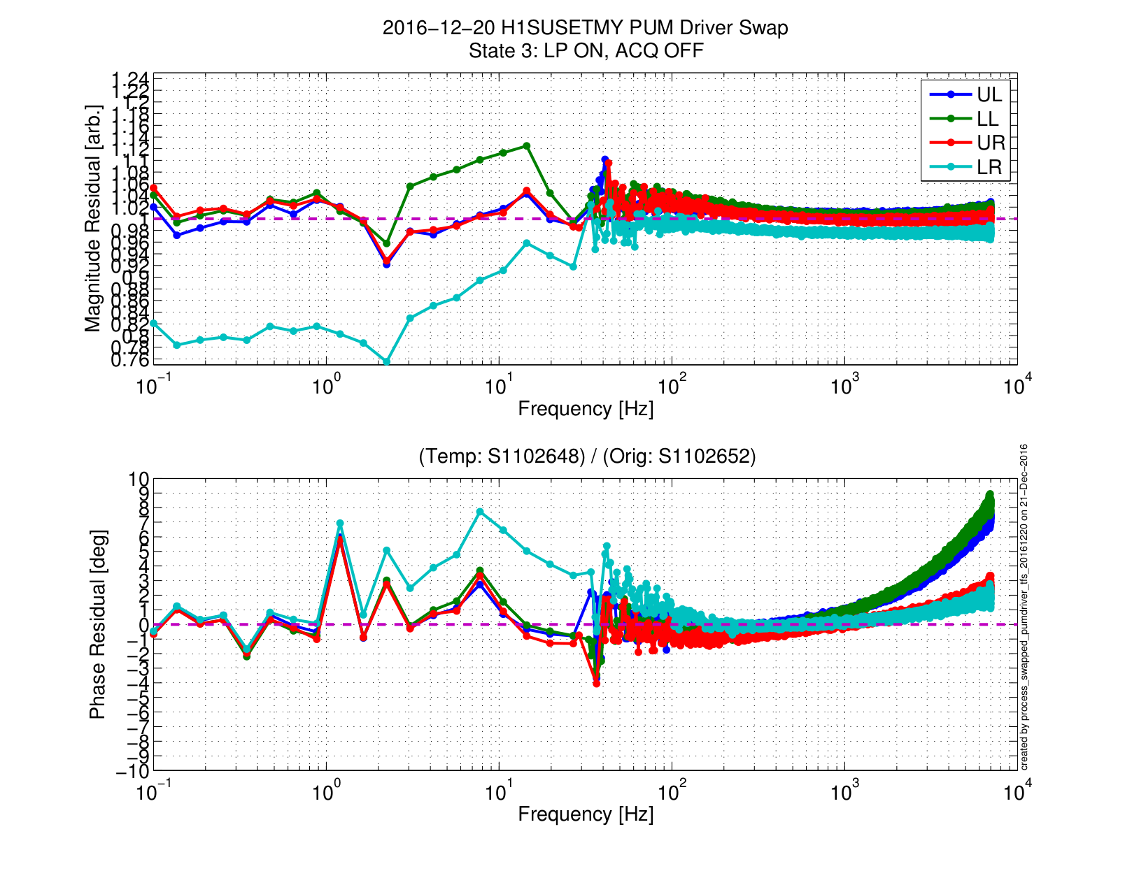
(3) The ratio of driver response for all four coils is shown in the same plot in the 3rd .png.
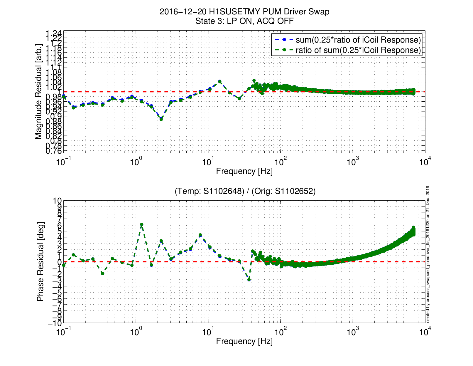
(4) To compute the impact of these changes on the longitudinal response of the stage, we show two traces in the 4th .png. Mathematically similar but not identical, I show
(a) the "average" (more accurately, the sum of each coil multiplied by 1/4) of the ratios from plot (3), and
(b) the ratio of the "average" of each driver's coils.
Plot 4 shows that, if we had left the temporary driver in place, then we would have a frequency dependent, +/- 4% / 5 [deg] systematic error in the IFO's response to gravitational waves in the 10 - 30 Hz region.
It also means, that for that 3 [hr] observation stretch on Dec 20th, we have this +/- 4% / 5 [deg] systematic error in the IFO's response in the 10 - 30 Hz region. For this reason, if at all reasonable, I suggest we create a data quality flag for that observation stretch. Otherwise, the librarian's nightmare of creating a new DARM model for just those 3 [hrs] would divert the calibration group's energy away from where I think our priorities lie in the foreseeable future.
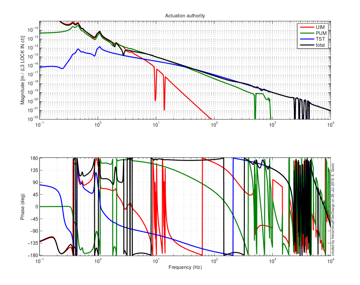
* This actuator authority comparison was generated by Evan, originally in LHO aLOG 28746. The script to generate these plot lives here:
/ligo/svncommon/CalSVN/aligocalibration/trunk/Runs/PreER9/H1/Scripts/HeirarchicalFilterDesign/HeirarchicalFilterDesign.m
and the plots from the entry live in the same directory.
** This data was taken when I expected that we were going to stick with the S1102648 PUM driver and needed to readjust the coil compensation filters (see LHO aLOG 21232). As such, the relevant frequencies are from 0.1 [Hz] -- enough below the lowest pole frequencies it can be separated from DC transconductance in fitting -- to 10 kHz where the impact of coil impedance begins to flatten out.
------------
The templates and exported data from this aLOG live in:
/ligo/svncommon/CalSVN/aligocalibration/trunk/Runs/O2/H1/Measurements/Electronics/
The script to analyze the data lives in:
/ligo/svncommon/CalSVN/aligocalibration/trunk/Runs/O2/H1/Scripts/Electronics/
The .pdfs of the attached plots live in:
/ligo/svncommon/CalSVN/aligocalibration/trunk/Runs/O2/H1/Results/Electronics/
Images attached to this report
Non-image files attached to this report
