
REMOVE SEARCH FILTER
SEARCH AGAIN
Search criteria
Section: H1
Task: COC
Ibrahim, Betsy, Oli
BBS01 AOSEM flag standoffs were removed, concluding gluing.
BBS01 was flipped to the HR Side via the inspection fixture.
Betsy and I then first contacted the HR Side (S1) and peeled an hour or so later.
We did not see any features or defects as we did with S2.


Ibrahim, Betsy, Rahul
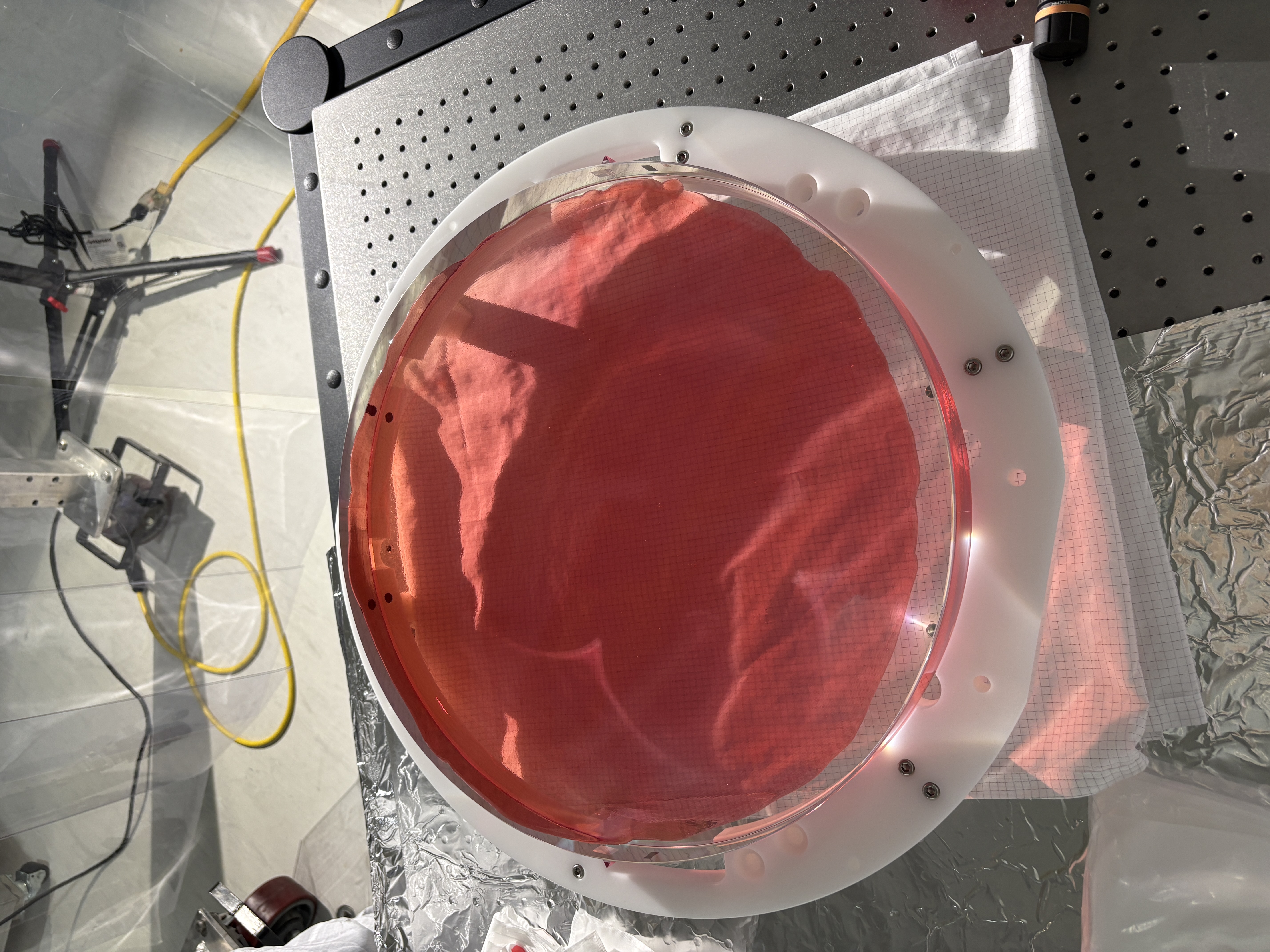
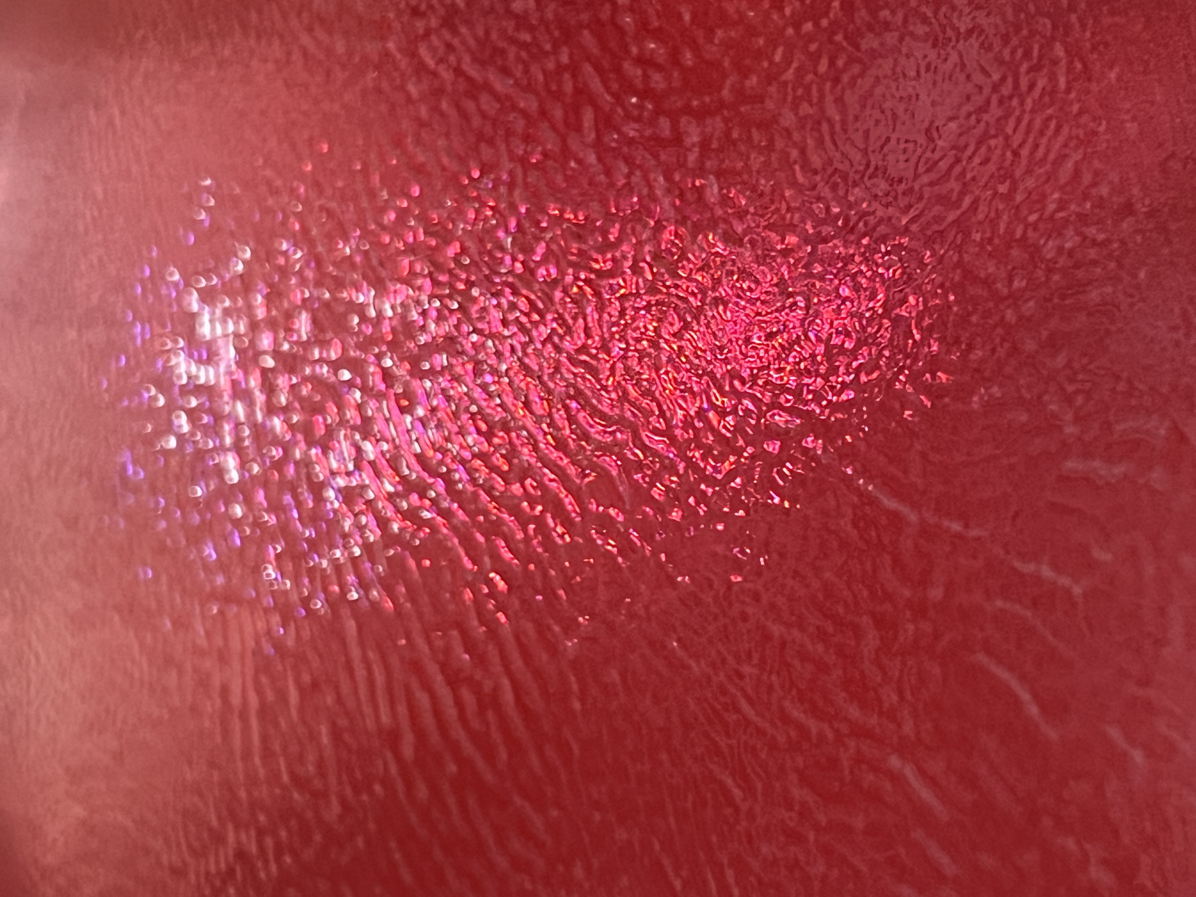
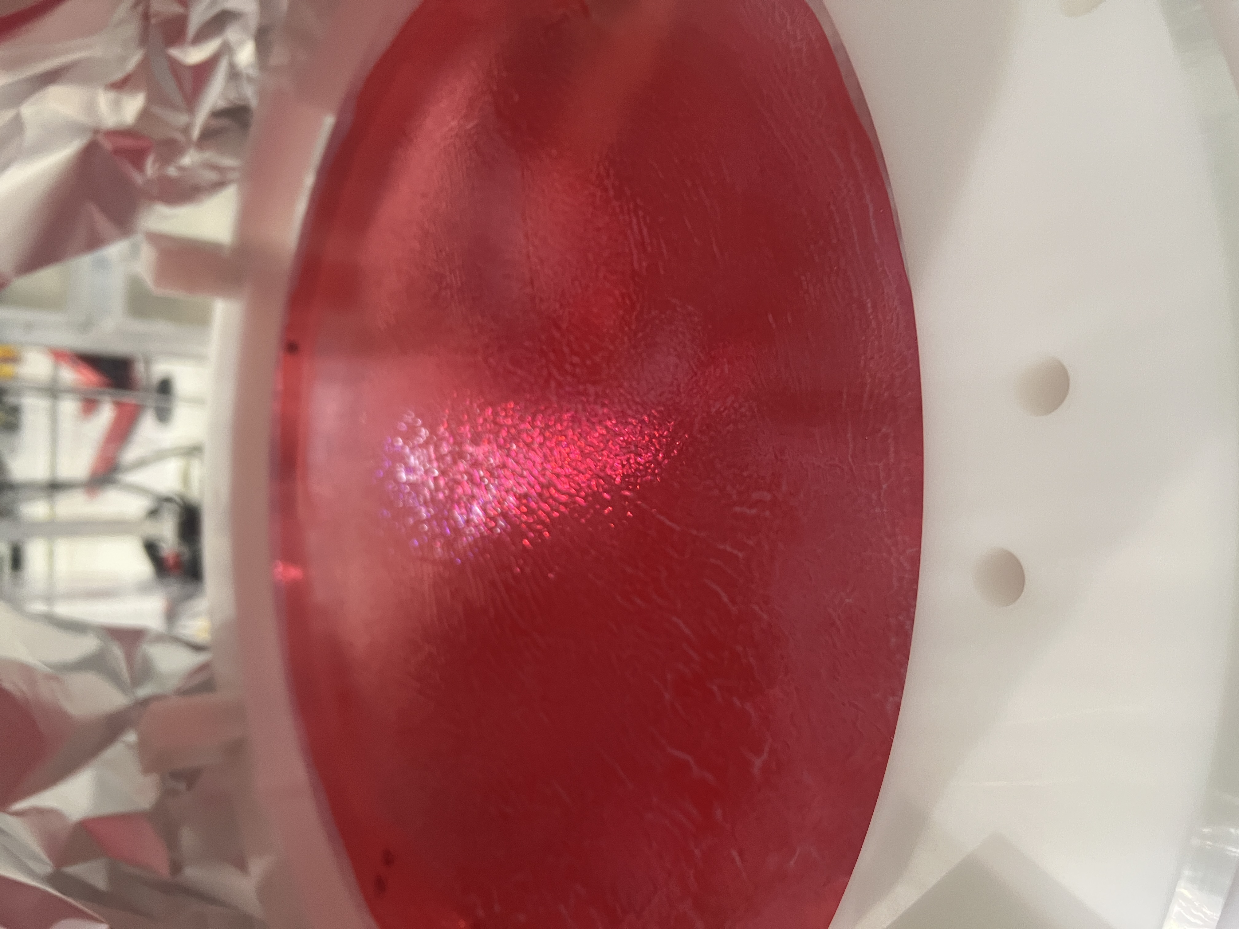
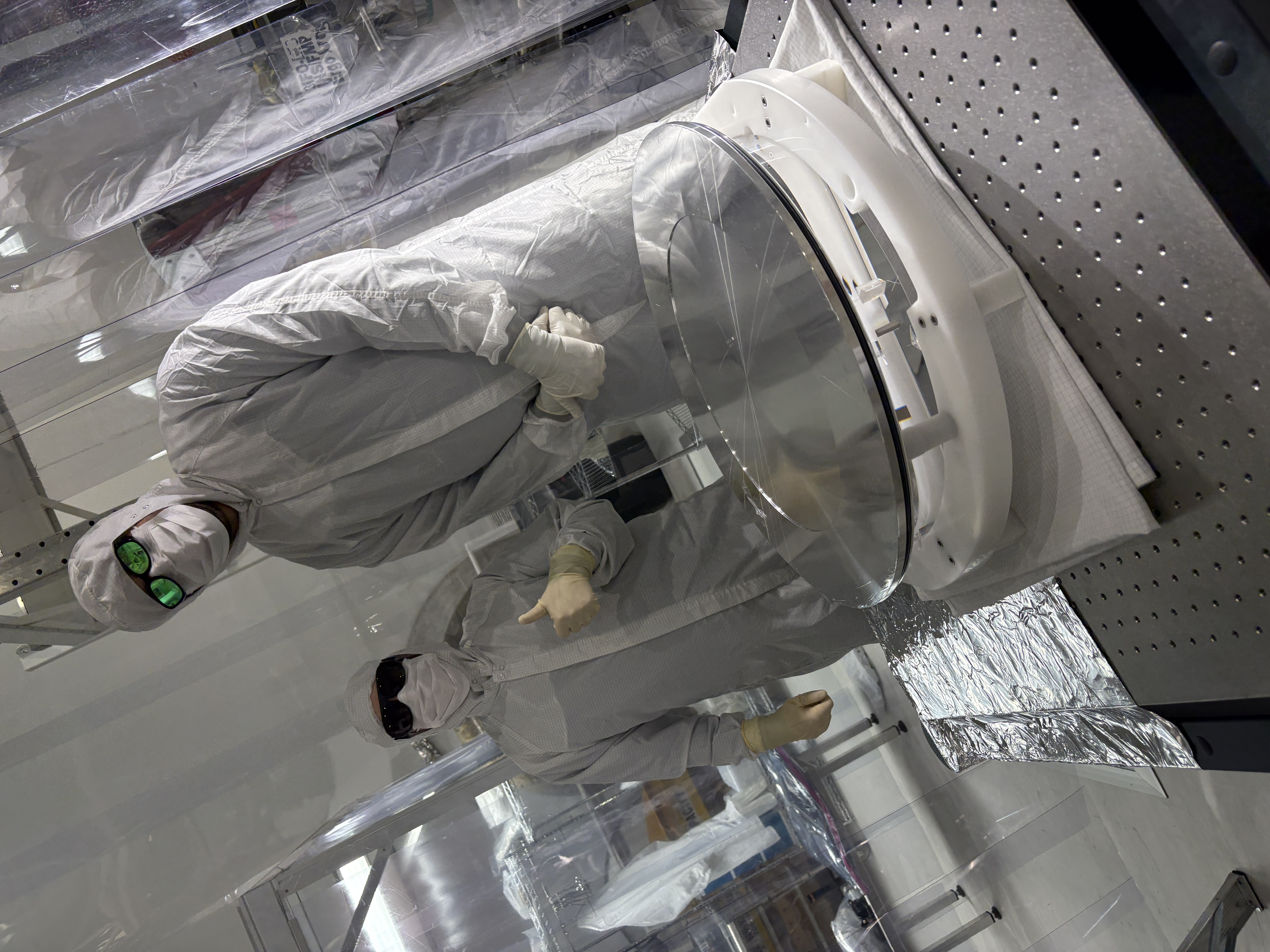
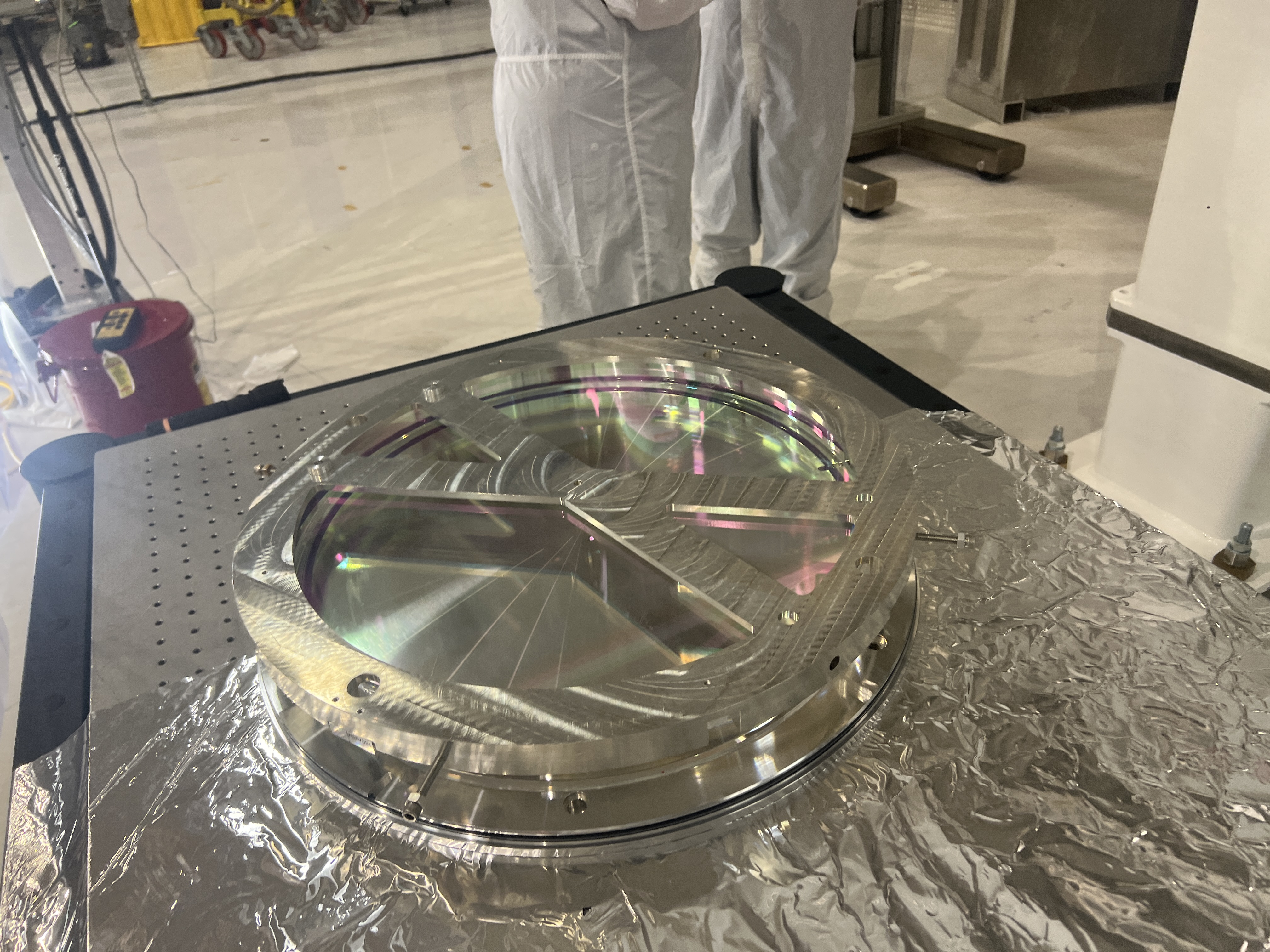
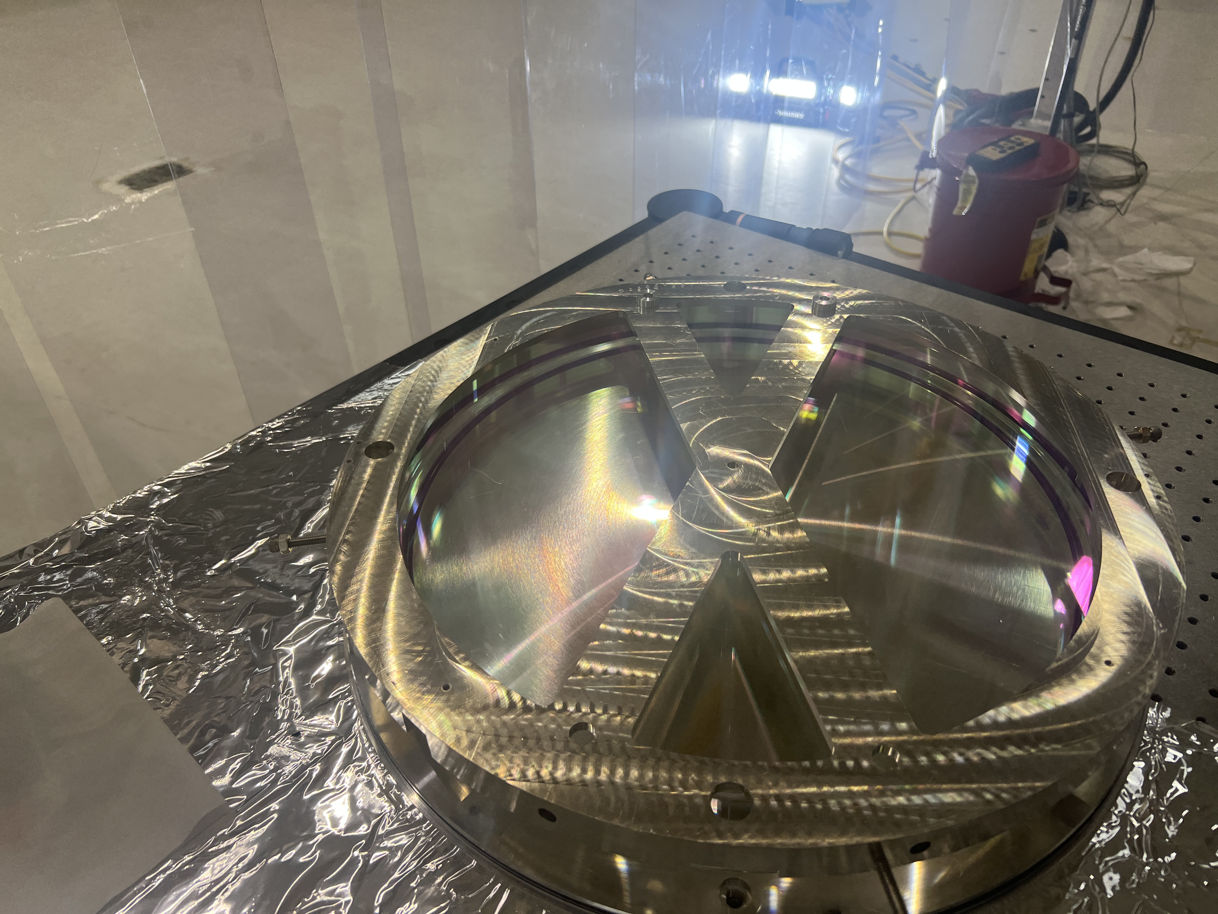
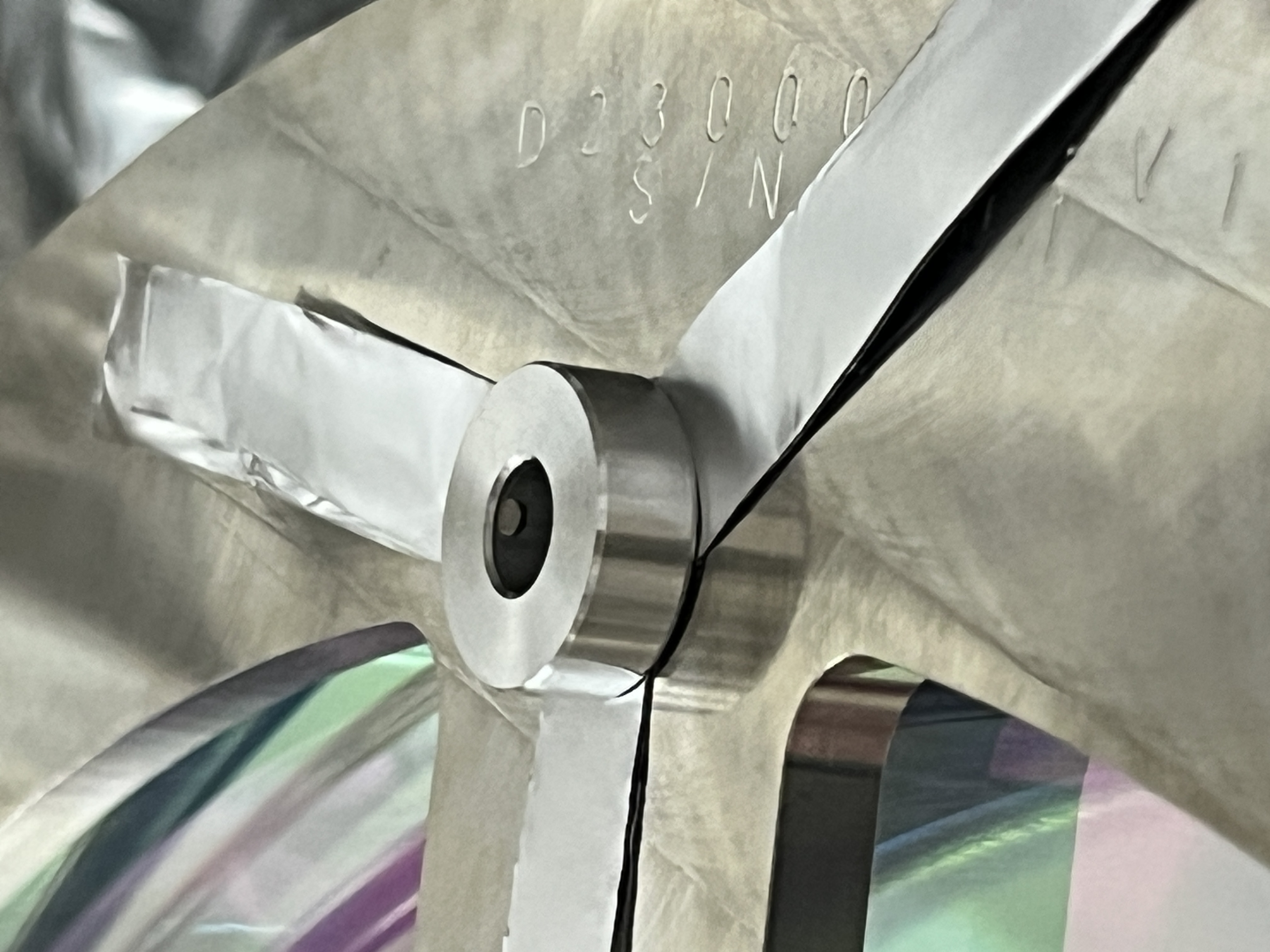
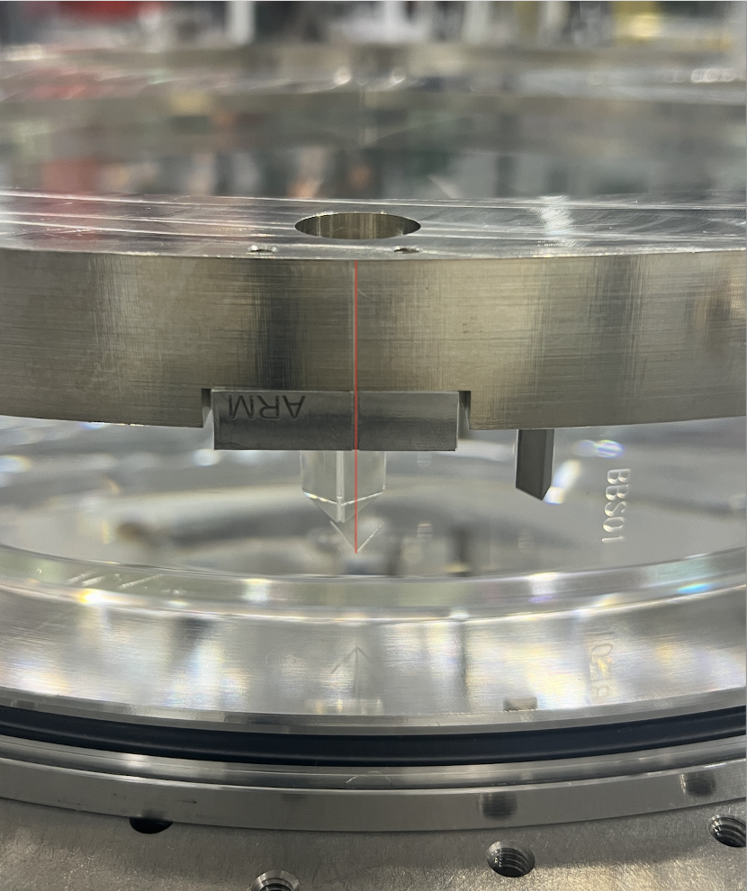
Today we glued two of the four AOSEM flag standoffs onto S2 of BBS01.
After gluing, we wanted to make sure we were contacted evenly so an hour and a half later, we used magnets to remove the flags from the glued-on mounts.
We discovered that some glue was touching the bottom of the magnet bushings, so we elected to use some foil as shims to create more space between S2 and the bottom interface of the bushings.
Otherwise, the mounts were flat on the surface. We put the bushings back on for the overnight cure. See pictures below.

Ibrahim, Betsy
Today, Betsy and I set up a Dino-Lite to image the spots we found yesterday (alog 90147).
Below are photos including before and after cleaning - according to the names of the files. None of the spots seemed to change after cleaning.
We also cleaned the spot that's in the center (not imaged with dino-lite) but it also did not go away.
Current most likely hypothesis is a coating defect due to circular nature of the spots and the resistance to cleaning.
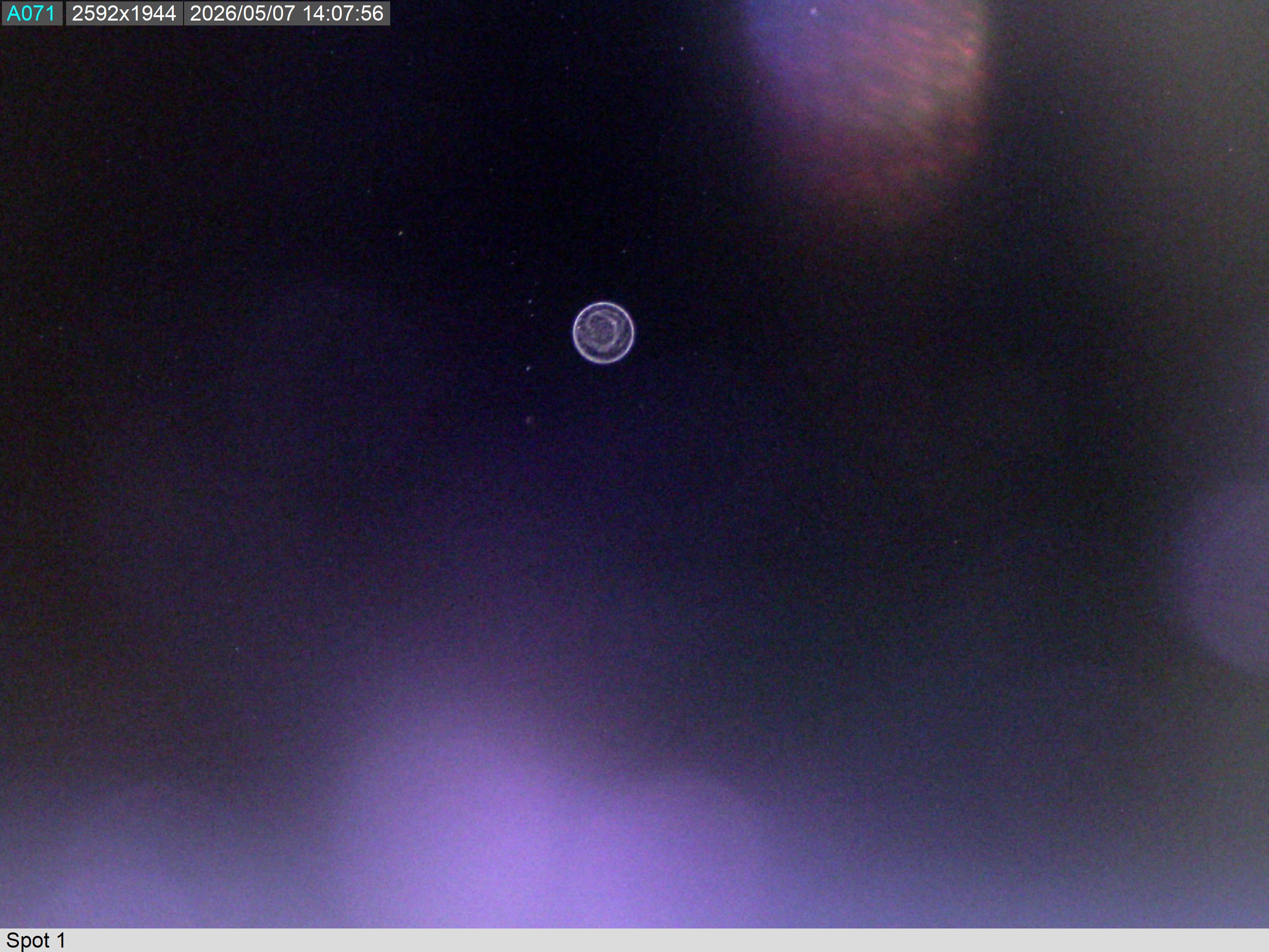
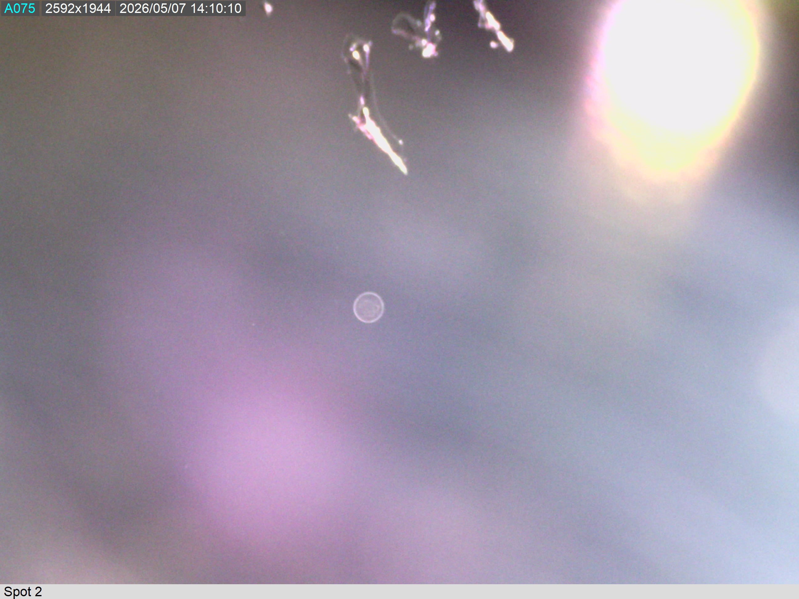

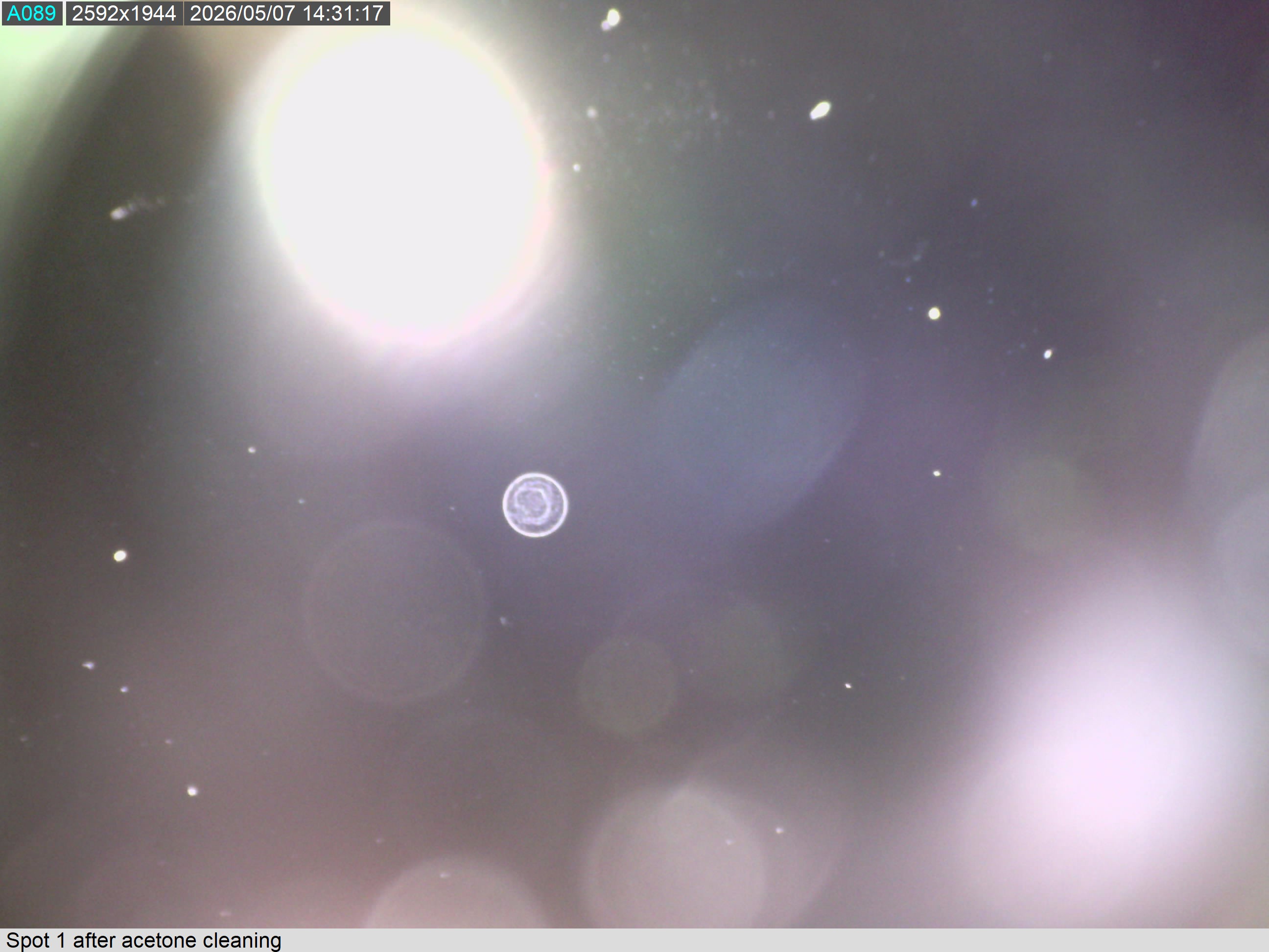
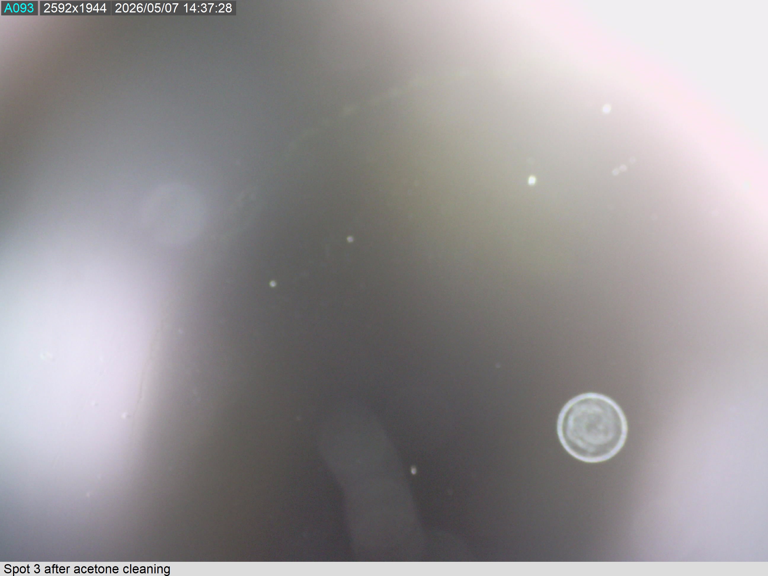


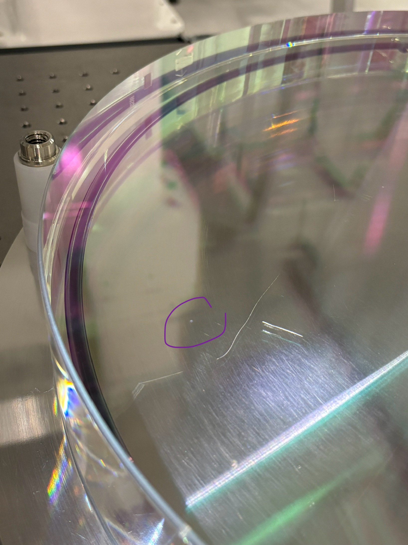
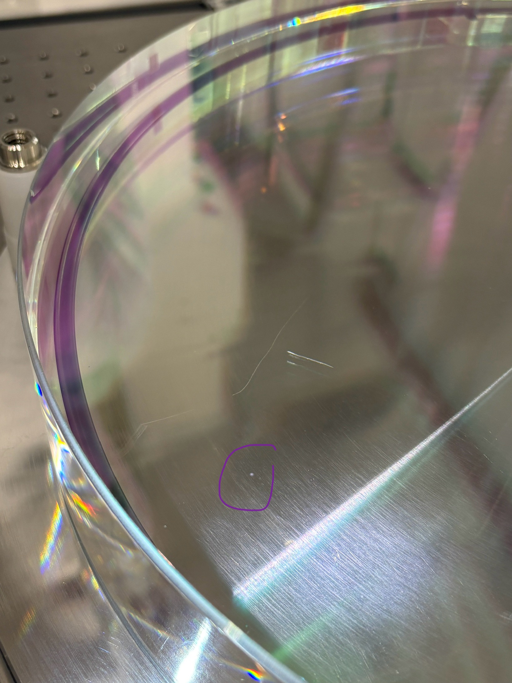
All of the spot pictures are un-cropped since the dino-lite was jigged to be roughly the same picture size and therefore show the relative spot sizes from one picture to the next. The last picture has a 2mm disc shown for scale (a banana was way too big, thankfully). The attached shows roughly where the 4 spots are. From some estimating on the pictures, spot sizes are roughly:
1: 0.5mm diam, bottom of the optic
2: 0.3mm diam, bottom of the optic
3: 0.6mm diam, centerline, but left a few inches
4: No pictures, almost dead center of optic so riskier to photograph, but much smaller like 0.1-0.2mm diam when visually comapred to the other spots

tagging for photos
Ibrahim, Betsy, Rahul
First contact was successfully poured on BBS01 AR side. Pictures below.
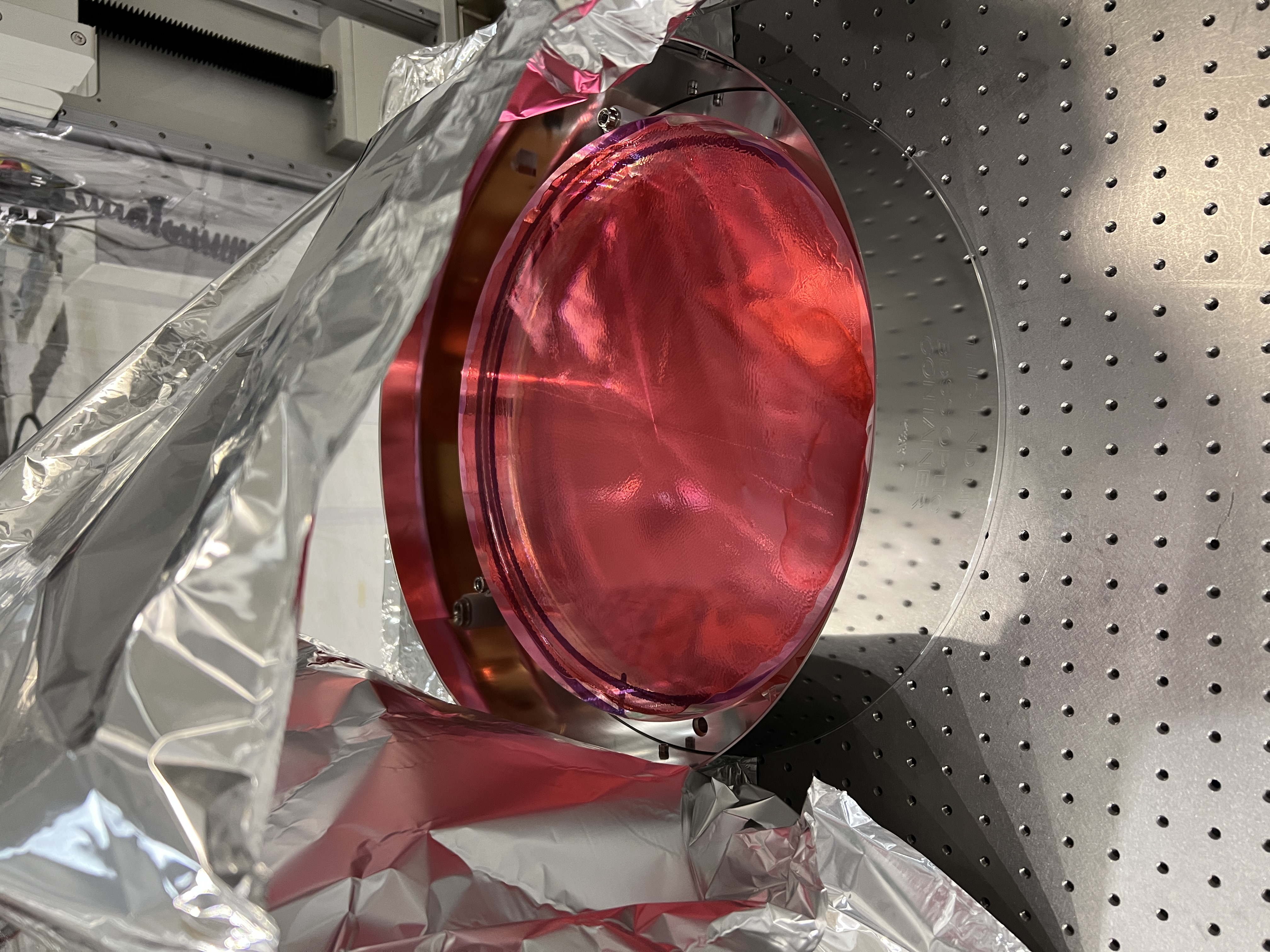
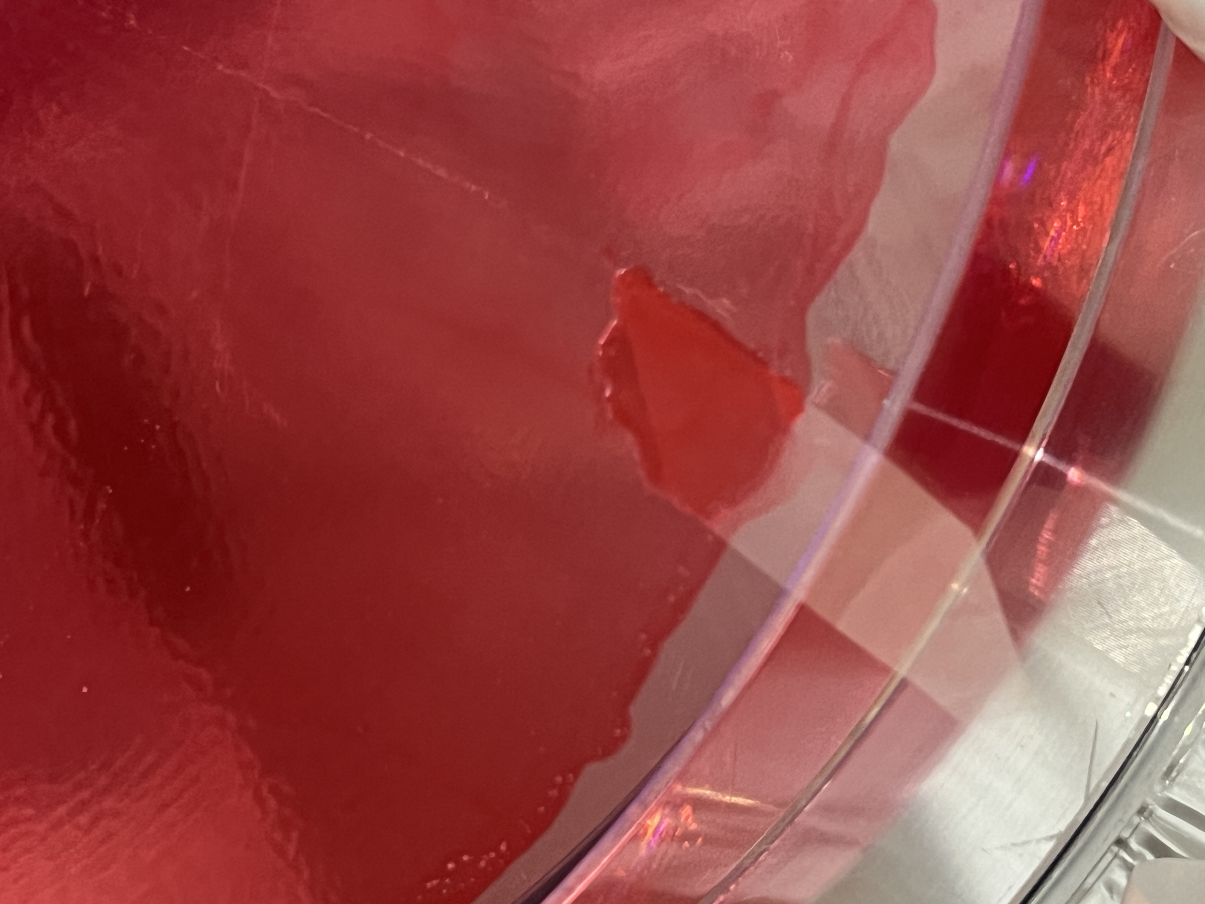
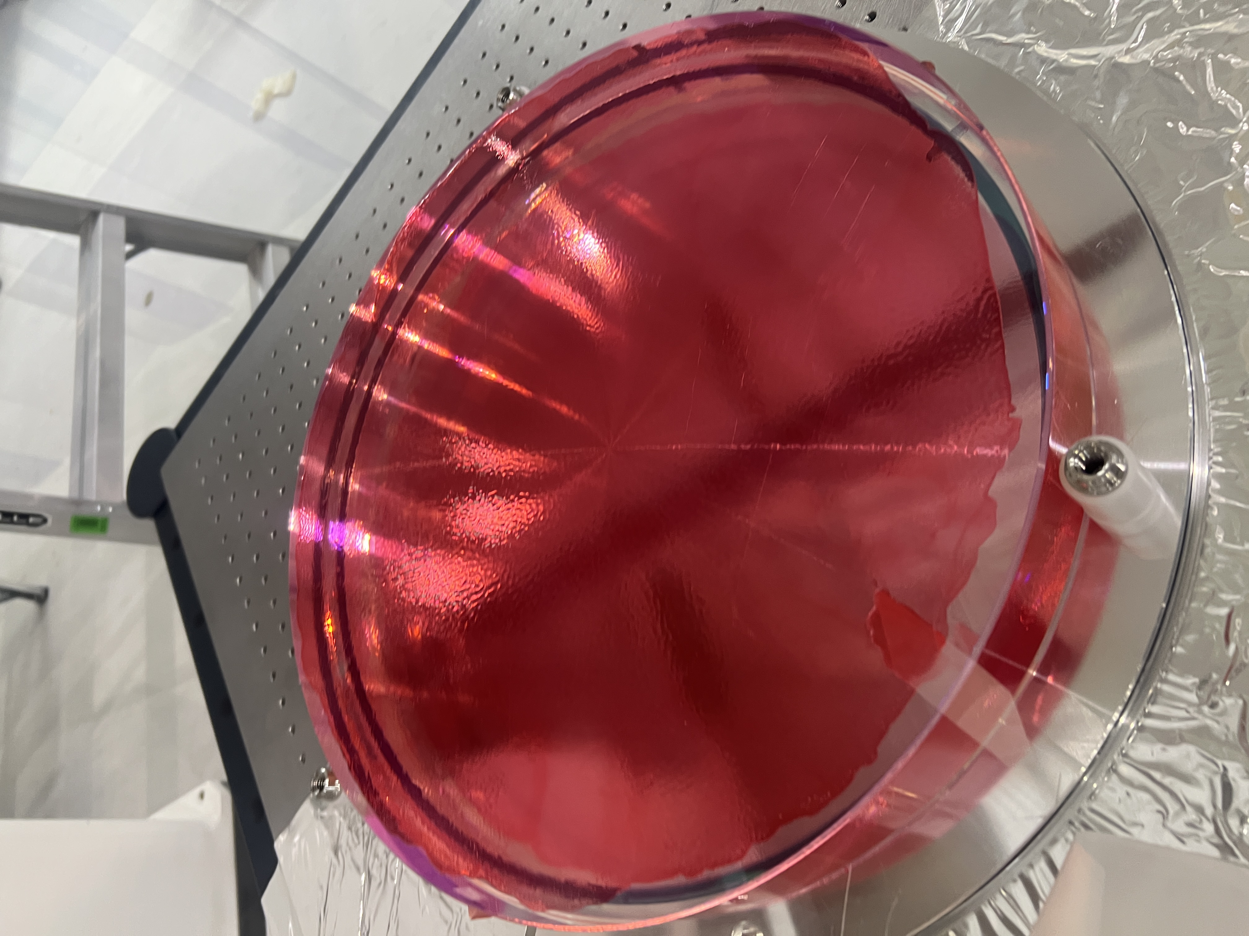
tagging for photos.
Ibrahim, Betsy, Rahul, GariLynn
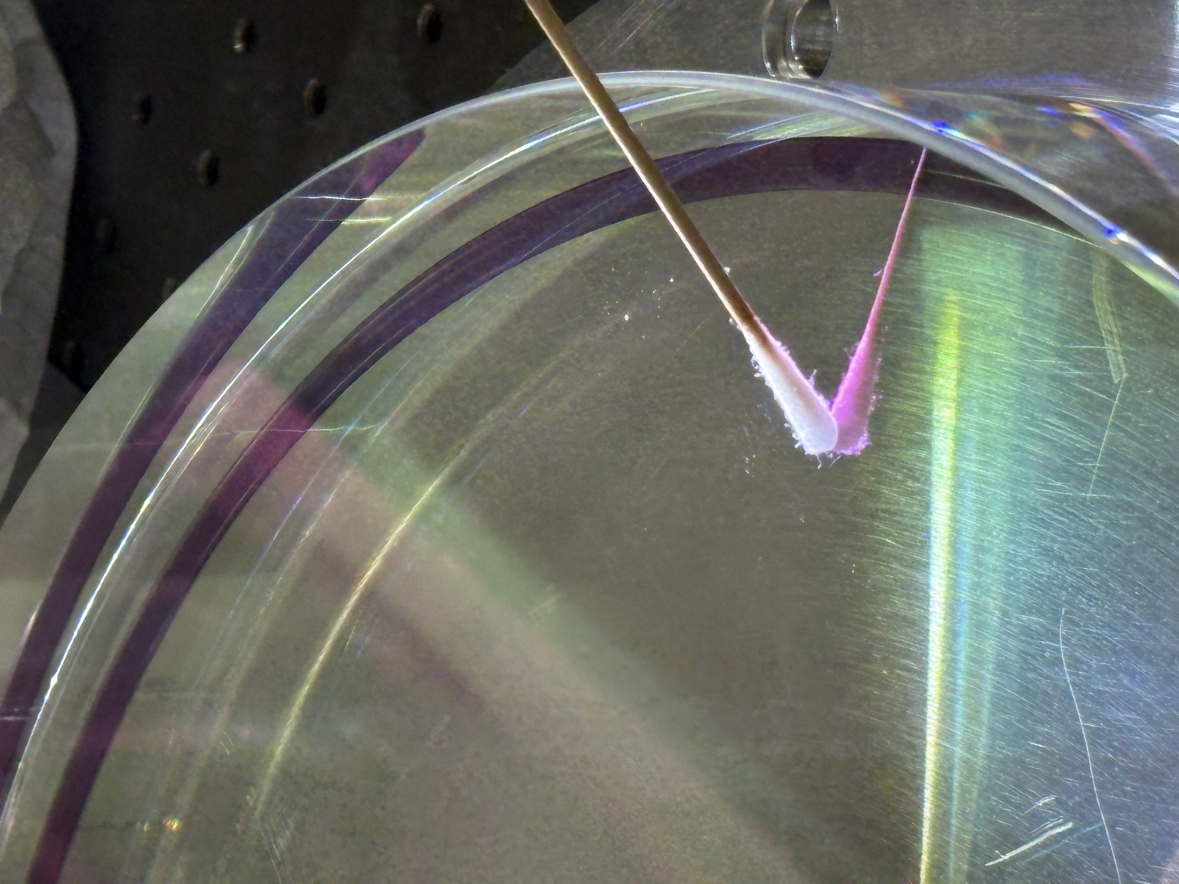
Following AR side first contact removal, we did our first flashlight inspection of the AR side (S2) of the optic. We found that there were 4 spots of varying size all under 1mm, perfectly circular. They seem to look like water (look at image). We contacting COC (GariLynn), who informed us this may be some coating defect. Nontheless, we tried cleaning it.
There are 2 smaller spots on the side of the optic (see image). There are 2 other spots near the center, with one being pretty dead on-center.
First, we used acetone with a cotton swab to wet two spots (the ones on the side). This didn't work and the spots were still there.
Second, we followed T1800350 to clean two spots with water, then immediately apply first contact. This didn't work either.
We will continue to clean spots with water tomorrow. Images below.


I had a look at the three SRC gouy phase measurements listed in 88155, this is related to commissoning modeling git issue 33
To do this, Evan Hall helped get me started using the current version of finesse (3.13.13) in the control room. Anyone can use this conda environment by using conda activate finesse.
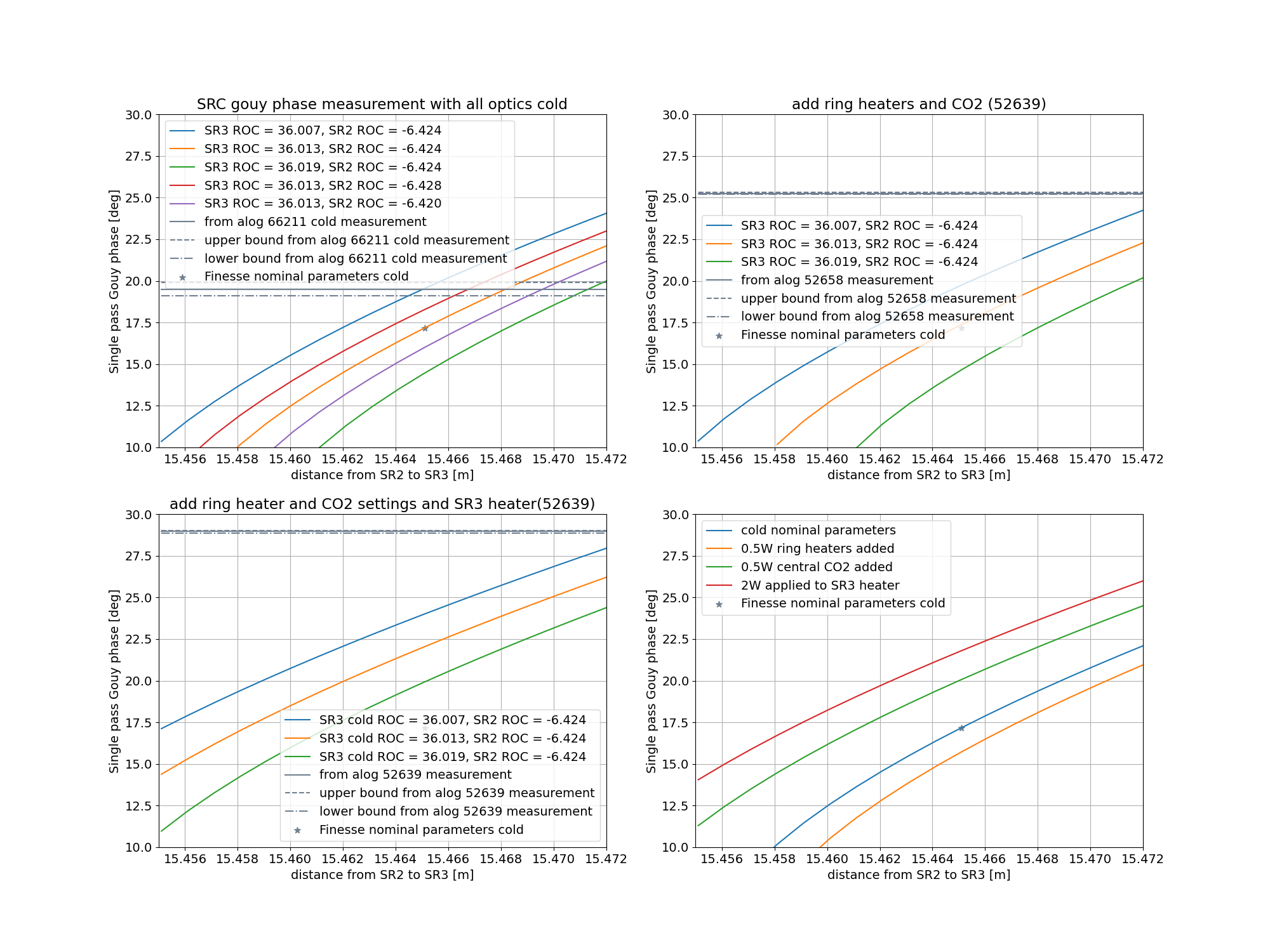
In the first plot, the upper left subplot shows the cold gouy phase measurement, which is reasonably close to the finesse prediction using nominal parameters from the LHO_O4.yml. I've added traces to show what happens when the SR3 ROC and SR2 ROC are changed by the rss error given by Garilyn, +/-6mm for SR3 and +/-3.7mm for SR2, and varied the distance between SR2 and SR3 around the value in the finesse yml. The gray band shows the measurement result, indicating that the gouy phase measurement could be explained by the nominal ROCs if the SR3-2 distance is longer than the value used in finesse by 3mm, or if the distnace is nominal the SR3 ROC could be shorter by 6mm to explain the measurement.
The next two panels show the two measurements made in October 2019, before the ITM replacement (52638 and 52658). The ring heaters were on for both of these measurement, decreasing the expected gouy phase, and central heating was also on which should increase the gouy phase. Using the TCS actuation strengths from 90004 we cannot easily explain these measurements as compatible with the cold state measurement.
The last panel shows the impact of each indivdual TCS actuator on the gouy phase measurement. The fact that all these lines are fairly close to parallel suggests that a series of measurements where we change only one actuator at a time could be a useful check of the actuation strengths.
In the second attached plot, I plotted the difference in gouy phase between having the heater on and off, which we can get from the comparison of the two 2019 measurements, with various parameter changes. I was wondering if we could use this difference to get information about the SR3-SR2 distance if we trust the HWS measurement of the SR3 heater strength. The 1.8 degree systematic uncertainty on the gouy phase measurements is large enough to make this seem not very promising.
The script used to make these plots is in the commissoning modeling repo here commit 8635b914

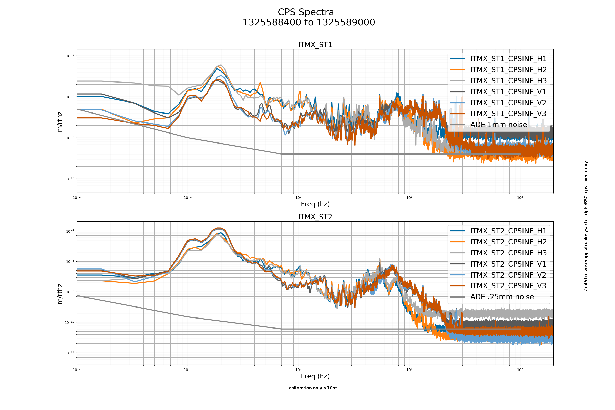
Maybe this isn't the best place to share this, but life can be frustrating as a deuteranope. Matplotlib has an easy to use colorblind friendly style built in. It can be invoked by adding the line plt.style.use('tableau-colorblind10') before starting to setup your plot (if you've used the usual import matplotlib.pyplot as plt). Maybe this is common knowledge, but I just found it while working on a script.
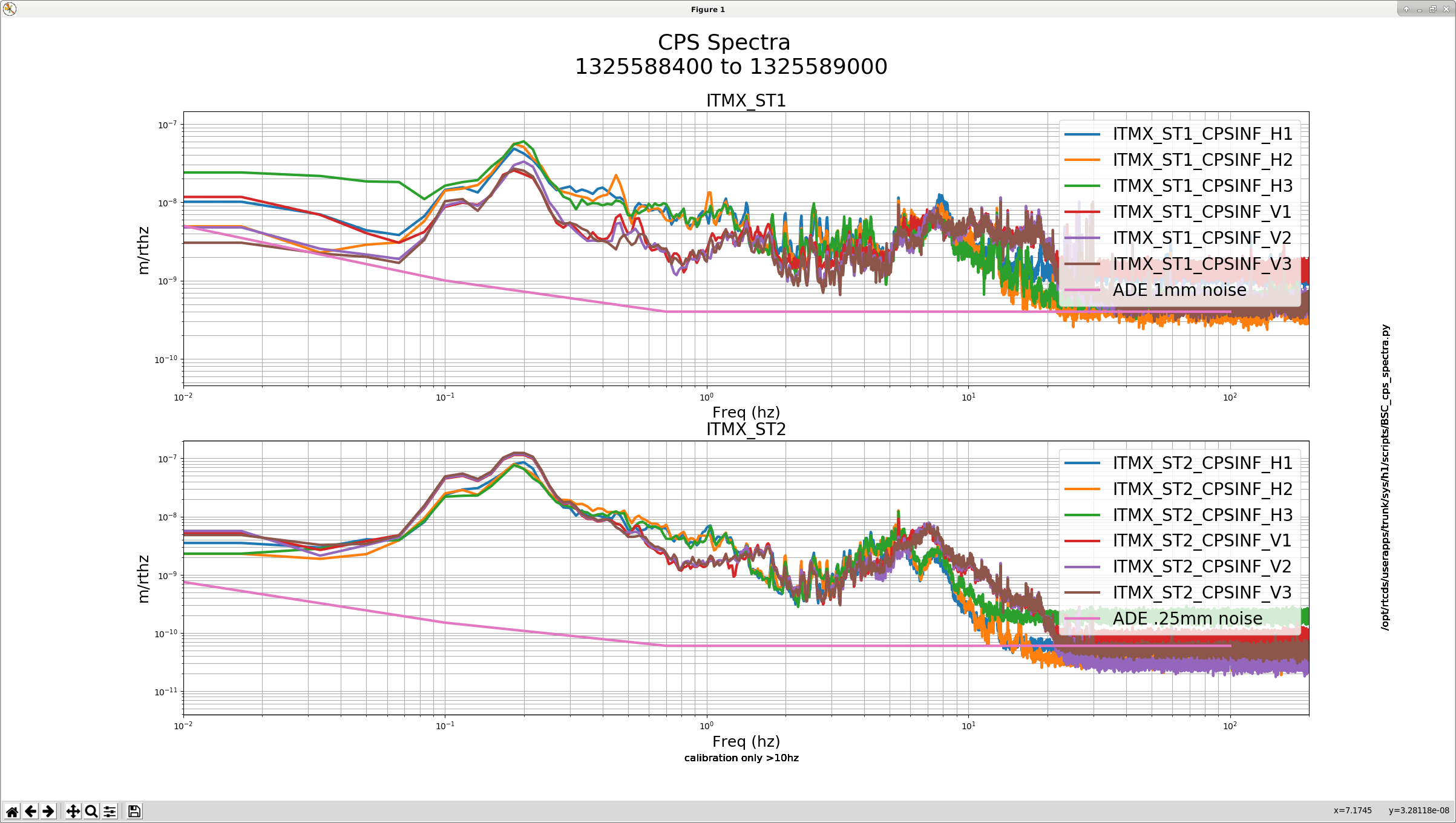
The first plot is one of the plots produced for the weekly CPS noise monitoring famis for ITMX. The second plt is the same one, but I added the colorblind style to the script. For me, on the first image the H3 and V1 sensors on both subplots are almost the same color. It's especially difficult to go between the legend and the traces on the first plot. Reading these plots on a backlit monitor make this even harder. More than a 4-6 traces, I have a really hard time telling which line is which.
On the second figure, it's much easier. Add in some different linestyles and thicknesses, and everybody's pretty plots can be appreciated by more people.
Nice one! Tagging all the groups, so some folks get emails about this dueteranope-approved color palate.

Now we just need the equivalent for matlab!
Today, Travis and I pulled the ITMX-HR FIrstContact cleaning layer and inspected. With bright light it was difficult to find many particulates in the main area of the center of the optic which was good. We fully suspended the 8 locked QUAD masses and returned the ACB back to it's nominal position (removed locking bracket and wedge). We then inspected the ITMX OPLEV laser transmitter and receiver beam with respect to the new nozzle baffles, and also check to confirm that for this ITM, the optical lever readback SUM is the same as it was before the locking episode. So all good there. A few quick TFs identified that I left a stop rubbing on the CP top barrel which Travis found, but the TFs look better now. Wafers are down in the chamber and we swept for tools, etc.
Nidhi is finishing the ITMY SUS TFs.
Jim is going to try to run ISI TFS of ITMX, ITMY, and the BS tonight.
Today, Travis peeled the BS FirstContact cleaning layers he applied last week. (We had to feed the N2 Top Gun and hose through the side of the HAM3 East door since that door was off.) Upon inspection, Travis found that there was some leftover FC streaks at around the 10 o'clock position on the AR surface of the optic, so he had to reapply the FC brush-on layer. The HR surface appeared clean. A few hours and a meeting later, we repeated the removal process, this time yielding a clean looking AR surface.
We unlocked the suspension, added the toilet seat shaped AR and HR baffles back onto the suspension cage, took a few pictures, pulled all tools from the chamber and exited. We redamped/untripped the ISI and BS SUS from the control room. The BS is not back to the nominal ALIGNED guardian state. HAM3 was still damped even though we were in the vicinity.
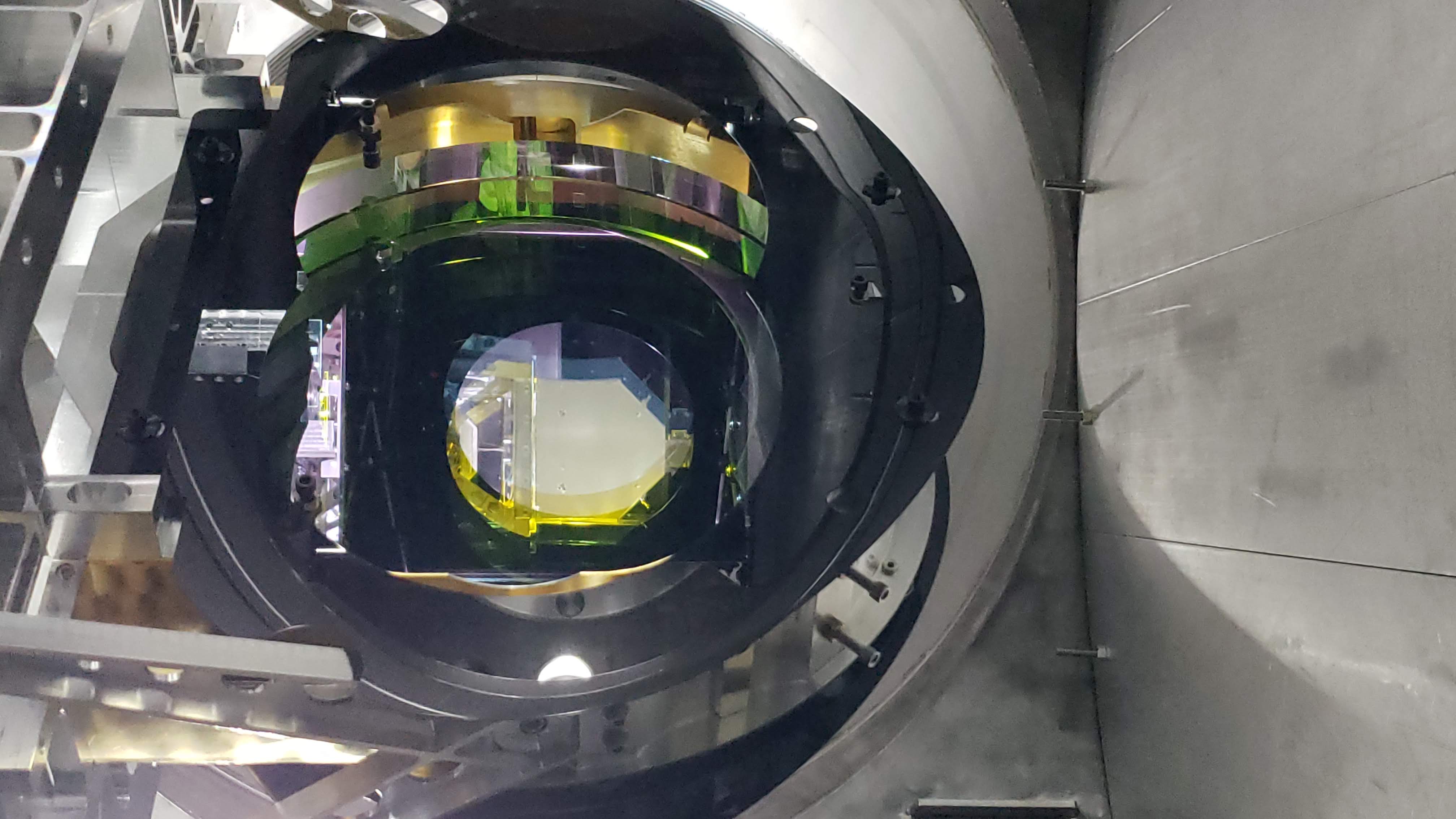
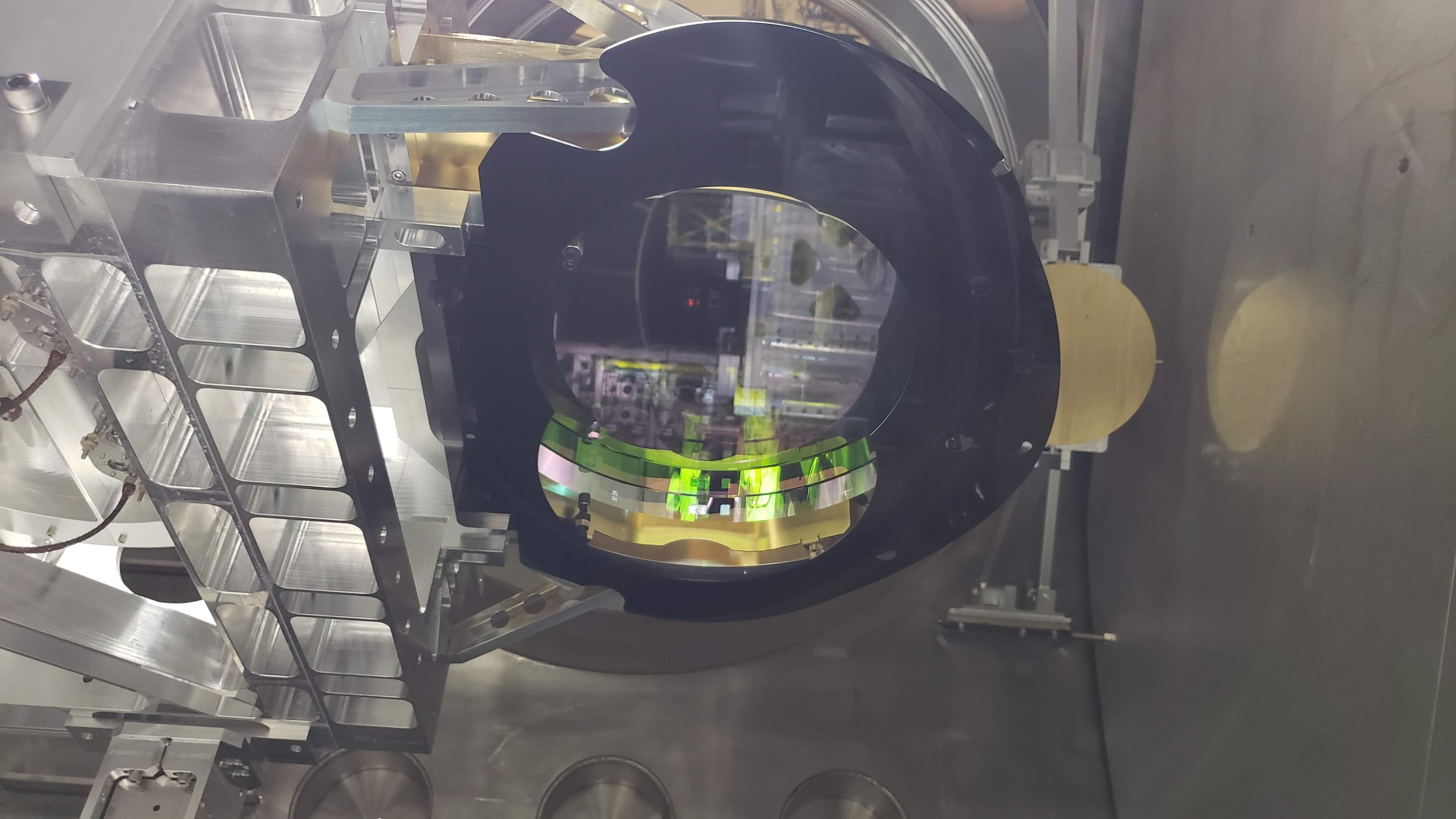
The first picture attached is the view of BS-AR from the SR3 perspective, showing how the gold barrel wire protection baffle on the left side is now less in the beam path than previously (recall it was cut per a new revision of the drawing and reinstalled). The second is the BS-AR as viewed from ITMX, again showing that the sharp edges of the right side baffle have been cut back per the drawing.
https://dcc.ligo.org/DocDB/0148/E1700418/001/BS%20WIRE%20BAFFLE%20MODS%20DETAILS.PDF
In prep for closeout of the BSC corner chambers, Camilla assisted me in applying First contact to the ITMY HR surface today.
We used the tooling bracket and wedge to push the ACB out of the way and we painted the cleaning layer onto the surface. It was decided to perform the painting application as opposed to the spray application, after Calum and I quickly l reviewed procedures again this afternoon. As well, the surface did not seem terribly dirty since there has been very minimal activity in this chamber, 0-5 particles per square inch.
Camilla also took note of the particle counts from the monitor very near the door, which were all around 20 and 40 or less during entry and exit of the chamber.
As Patrick recorded in his summary from yesterday, we have put the ITMY in the SAFE Guardian state and then removed many of the OSEMs. So, ignore any error signals from th ITMY SUS. (Recall the BSC1 HEPI and ISI are locked so those states are also now static.)
Yesterday, Travis and I got so far as to lock all of the masses and muscling through the removal of most of the hardware on the QUAD needed in prep to remove the lower structure (and lowest 6) masses of the ITMY QUAD. We plan to do the deinstall with the arm on Monday. We noted a fair amount of metal particulate on the bottom of our shoe covers each time we exited the chamber.
Prior to disassembly, Travis marched down to the ITMY Optical Lever receiving viewport and double checked our previous mapping. Namely, with bias enabled for the main and reaction chain, the ITMY-HR beam is ~centered on the OPLEV diode (as confirmed by Kissel's trends yesterday) and the ITMY-AR overlaps the CP-HR very well. I'll add the sketch soon.
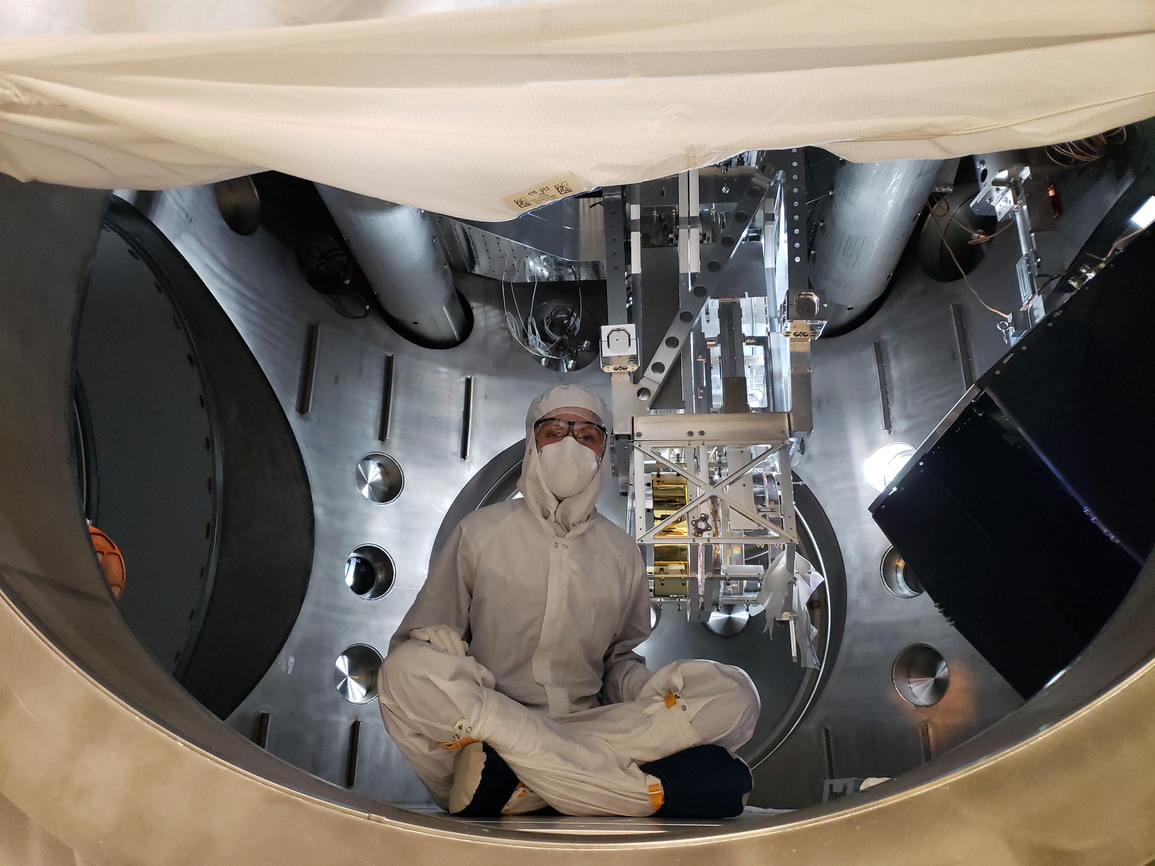
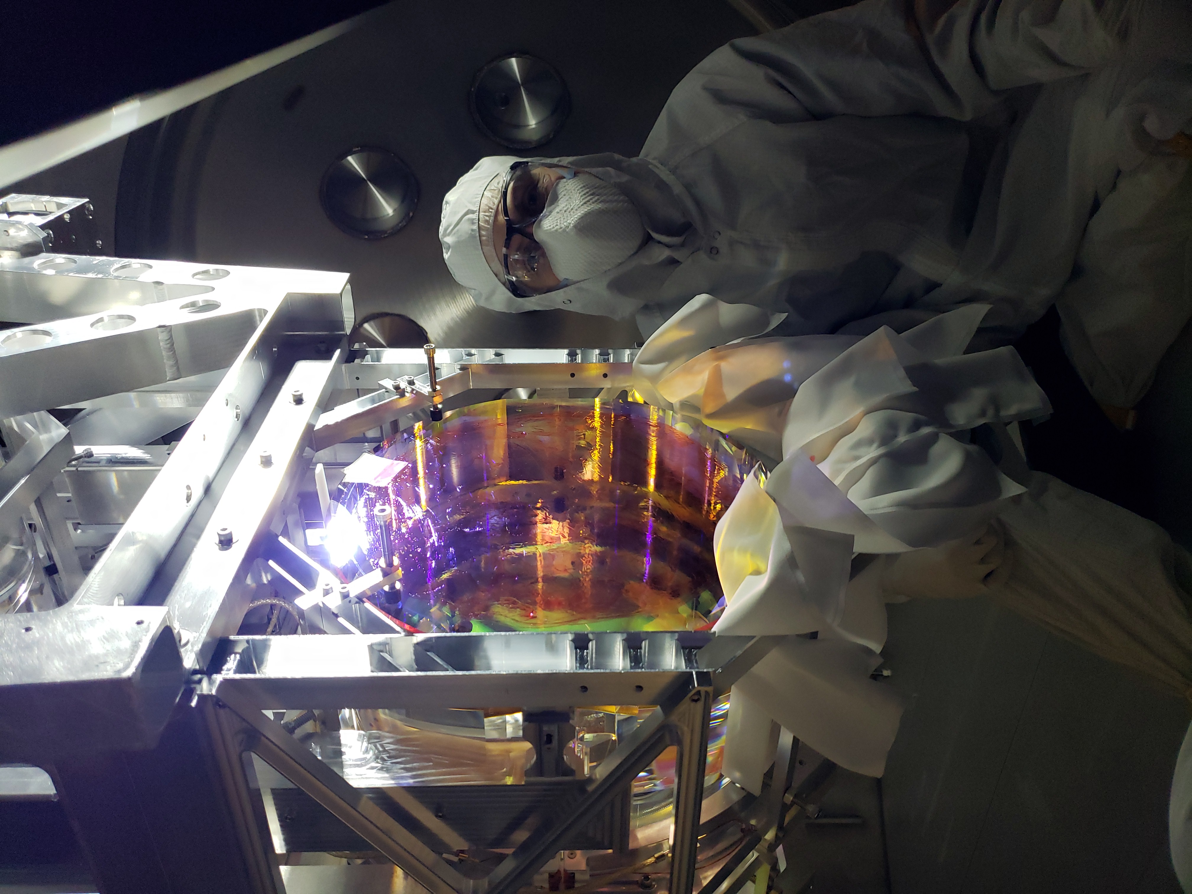
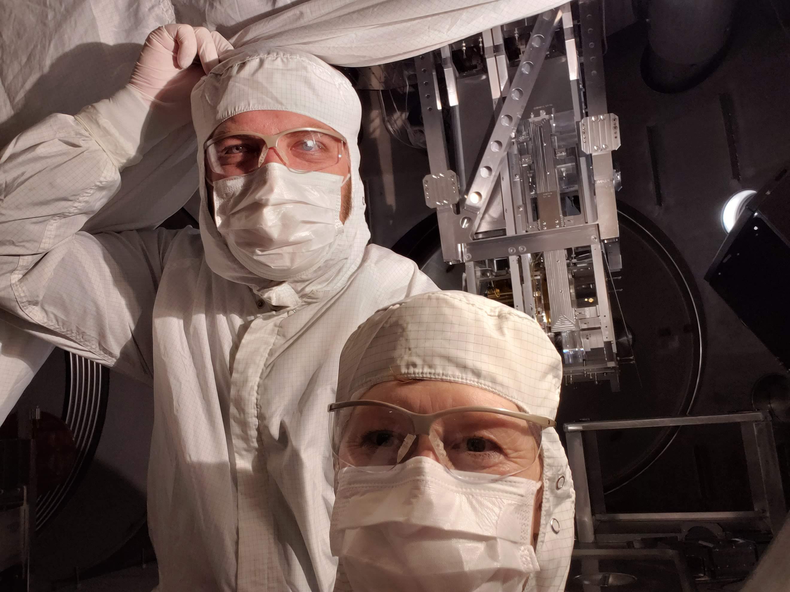
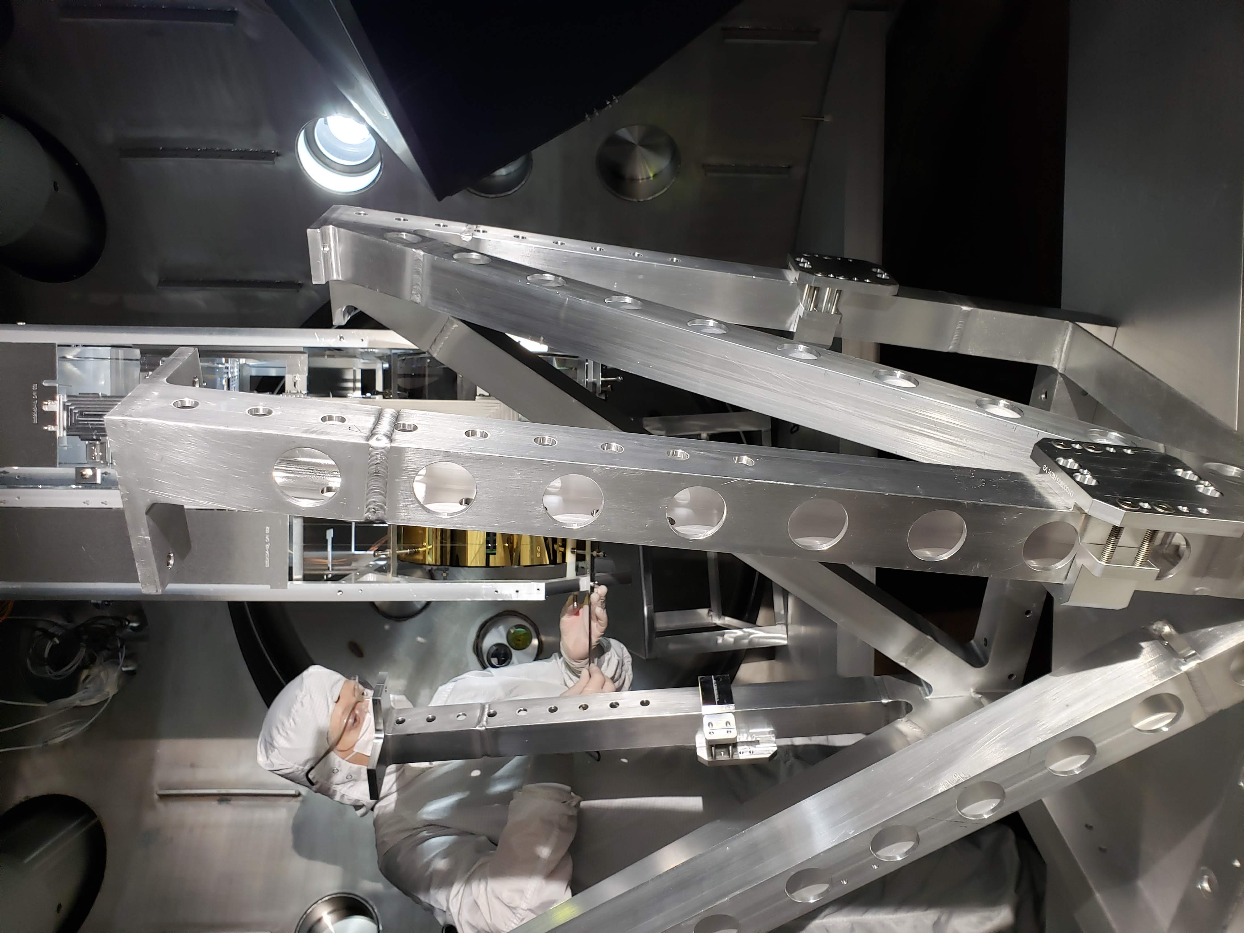
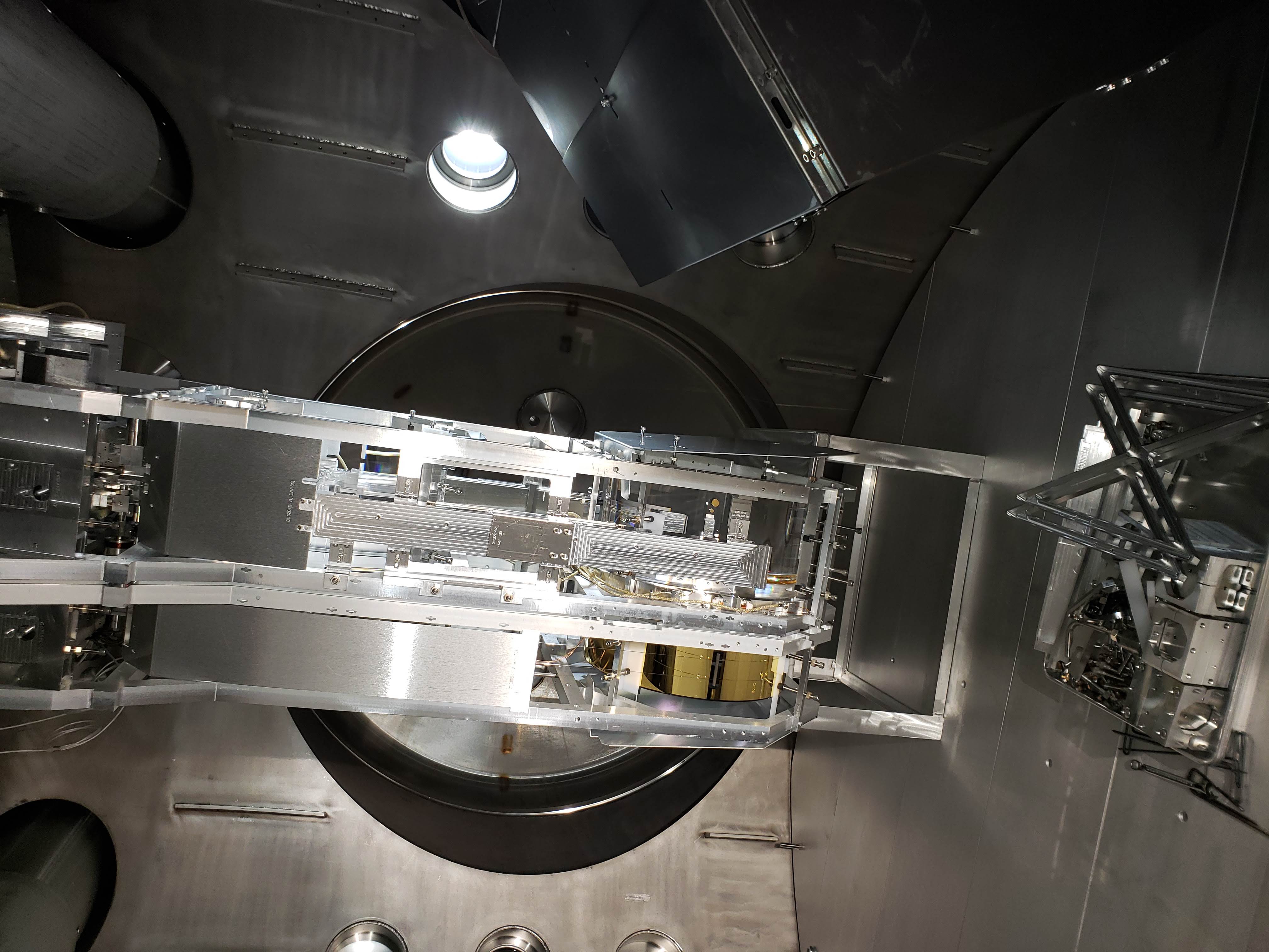
Pictures attached are 1) ITMy pre-disassembly, 2) disassembly in process (ACB swung back, floor planks removed, sleeve removed) and 3) ITMy bit naked and ready for arm-assist removal.

For the record, the new ITMY optic (ITM01) was weighed after the ears were bonded and comes in at: 39,611g
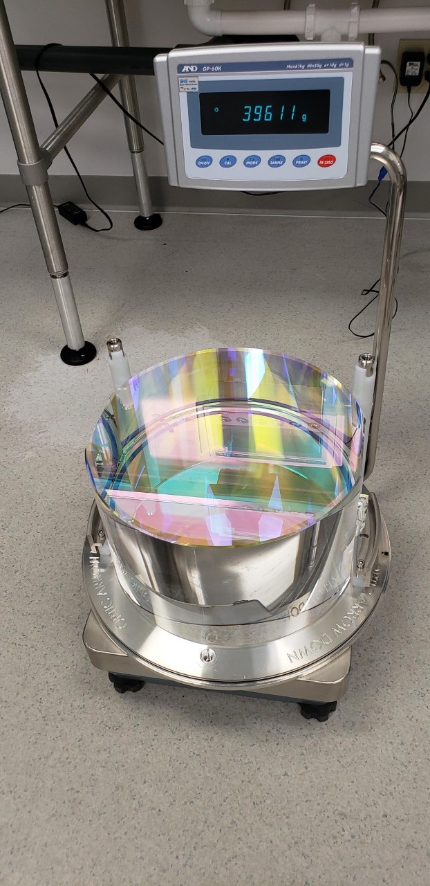
Gerardo and I, with Rahul in training, bonded PUM ear S1201472 to the test mass ITM01 S3 flat. (Yes, a PUM ear on a test mass - this was deemed acceptable in times of short test mass ear supply.) The bonding was straight forward and placed with 0.04mm measured error along the beam path axis (0.1mm is the tolerance).
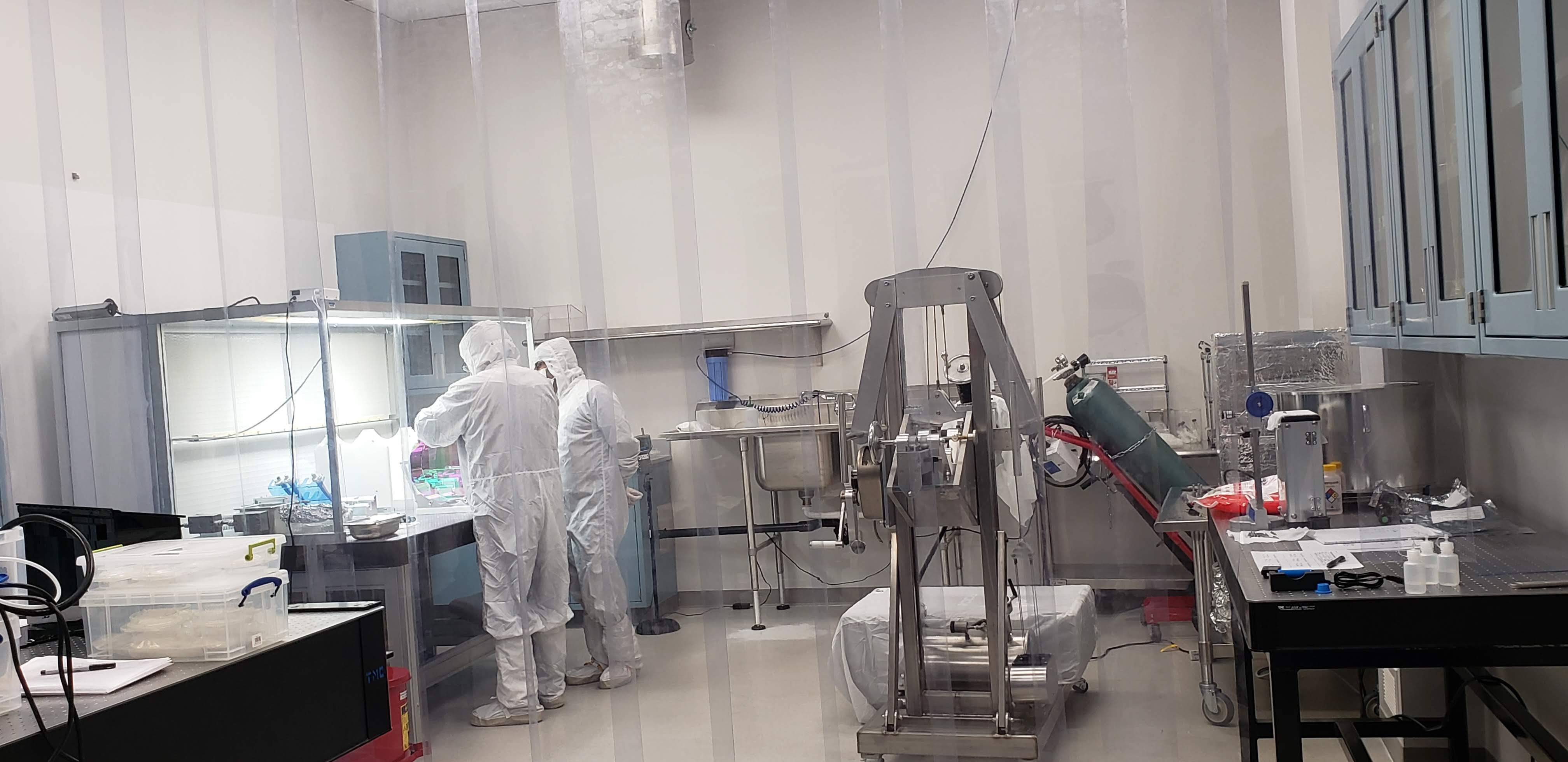
Note this was the first bond in the new lab space. All systems up and working well, thanks to Bubba/Tyler/Chris and the many hours Travis spent to help move everything.
The second ear bonding session is scheduled for next week.
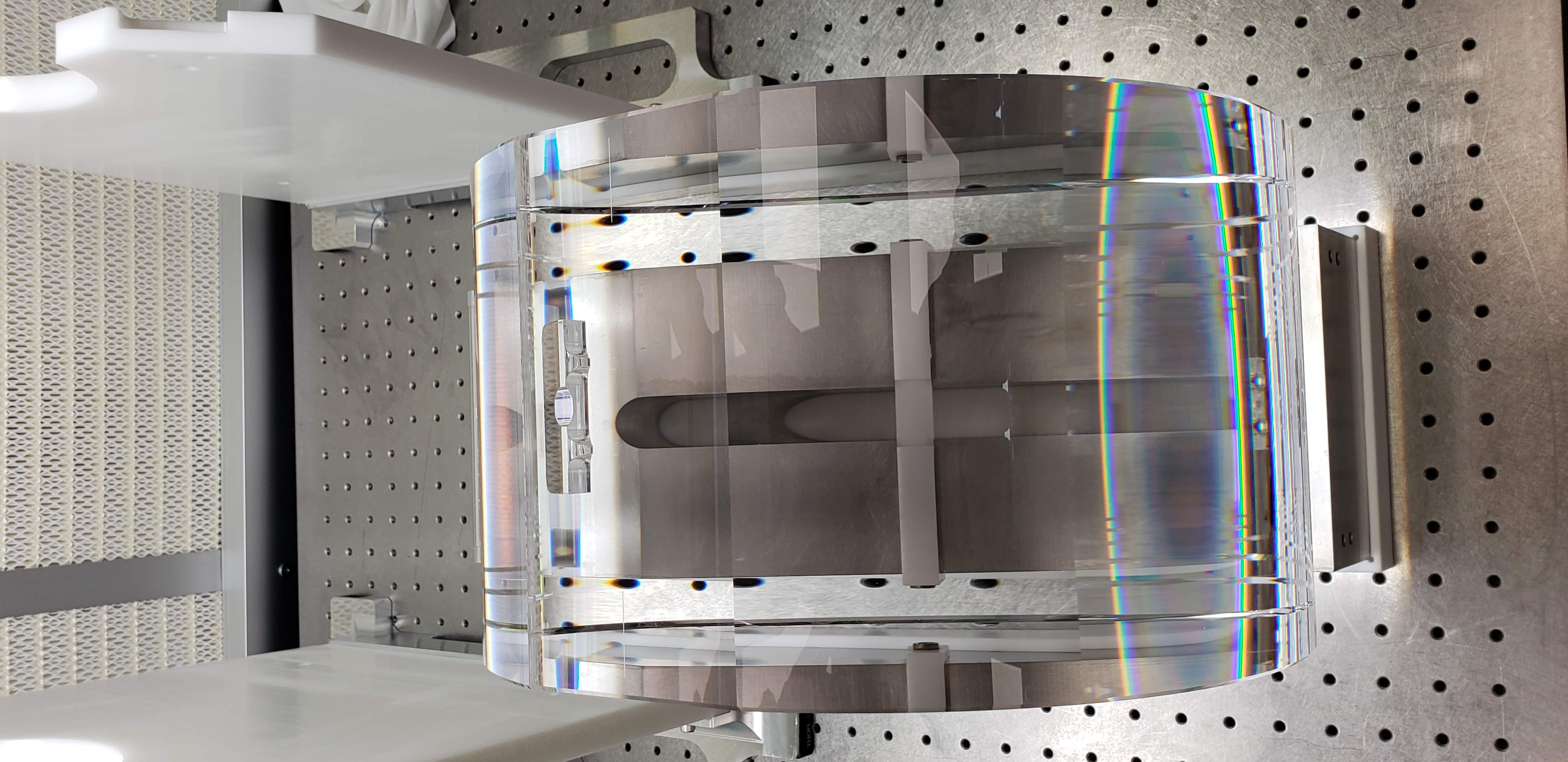
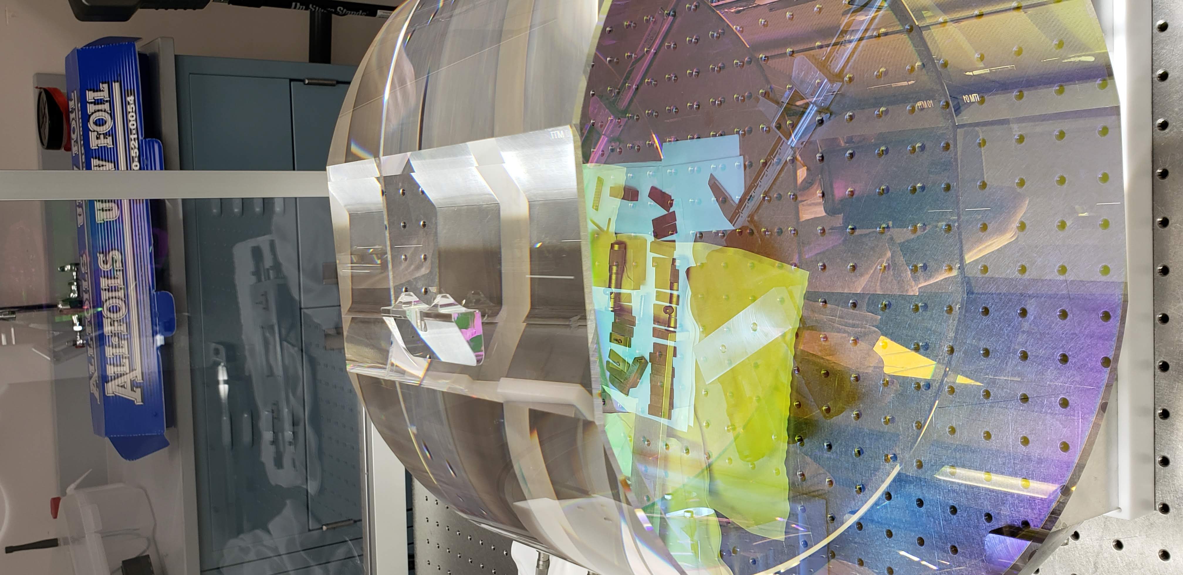
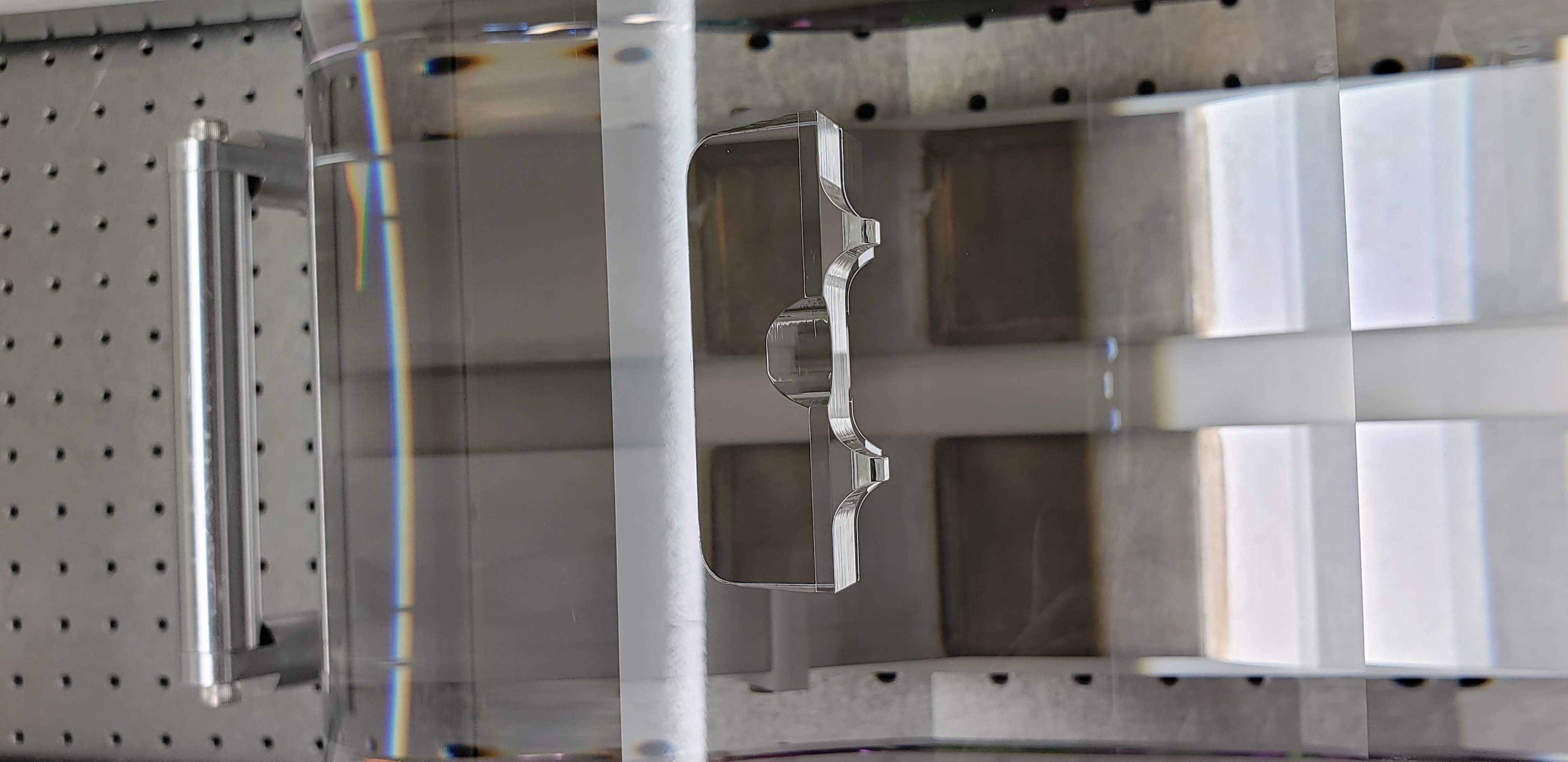
Late entry - ITM01 had the second ear bonded on March 4th, 2020.
A PUM ear was again used. Ear - S1201484
During the bond, there was initially a set of bubbles which we watched migrate out over the course of a few hours. At 2 hours the location and bubble situation (very minimal) were well within tolerance.
The optic will be FirstContact cleaned and stowed in the coming week.
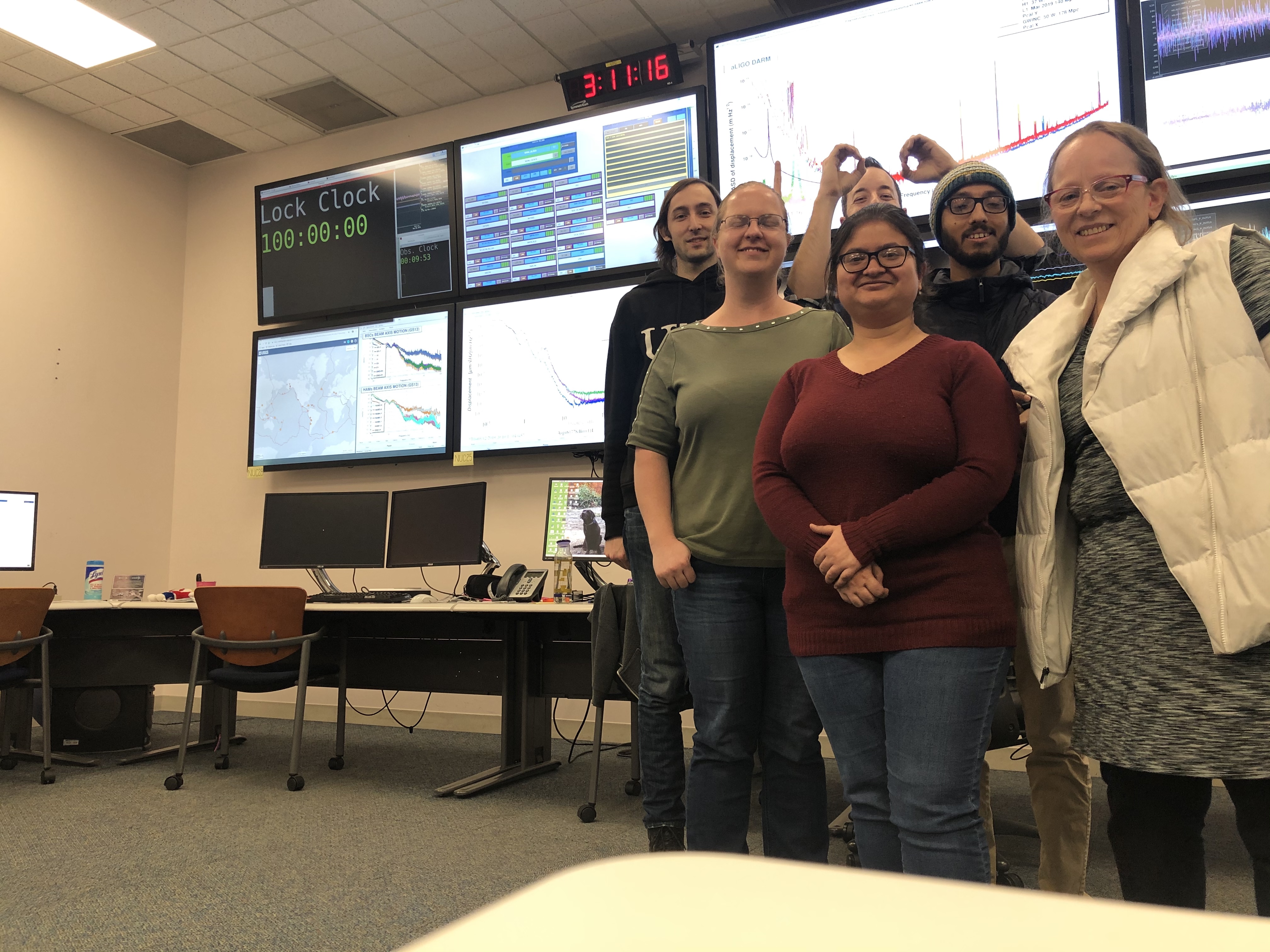
4 hours 48 mimutes 26 seconds later, H1 is still locked, and GPS time rolls over to 1260000000.
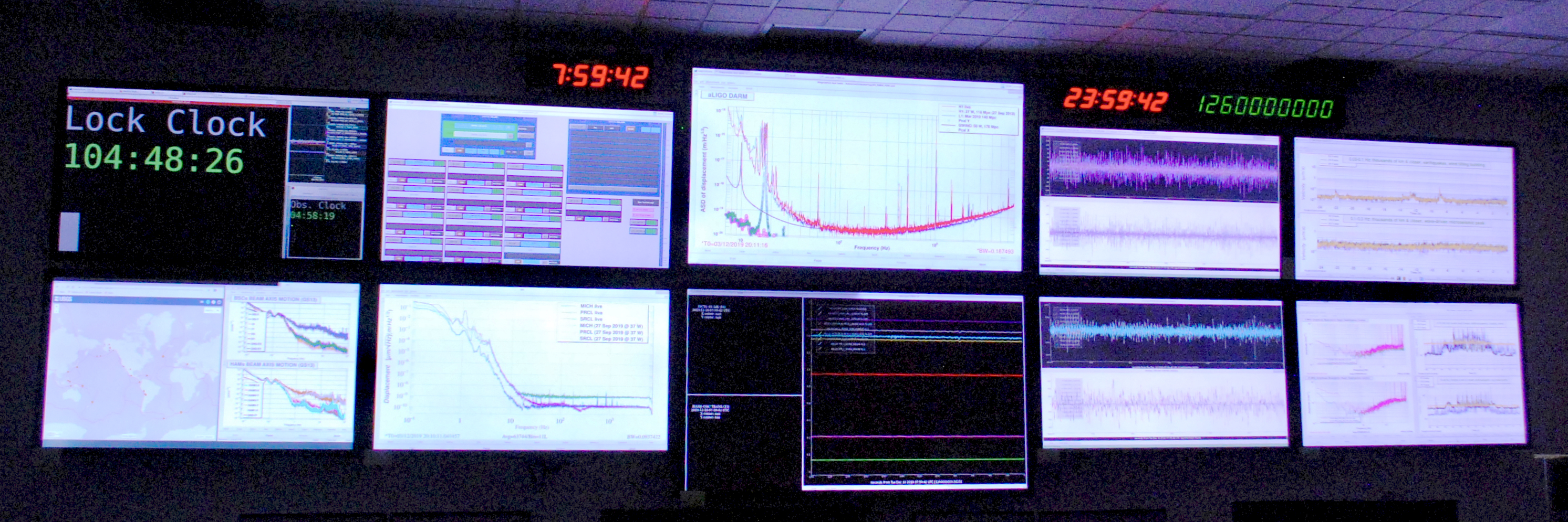
Very nice!