REMOVE SEARCH FILTER
SEARCH AGAIN
Search criteria
Section: H2
Task: IOO
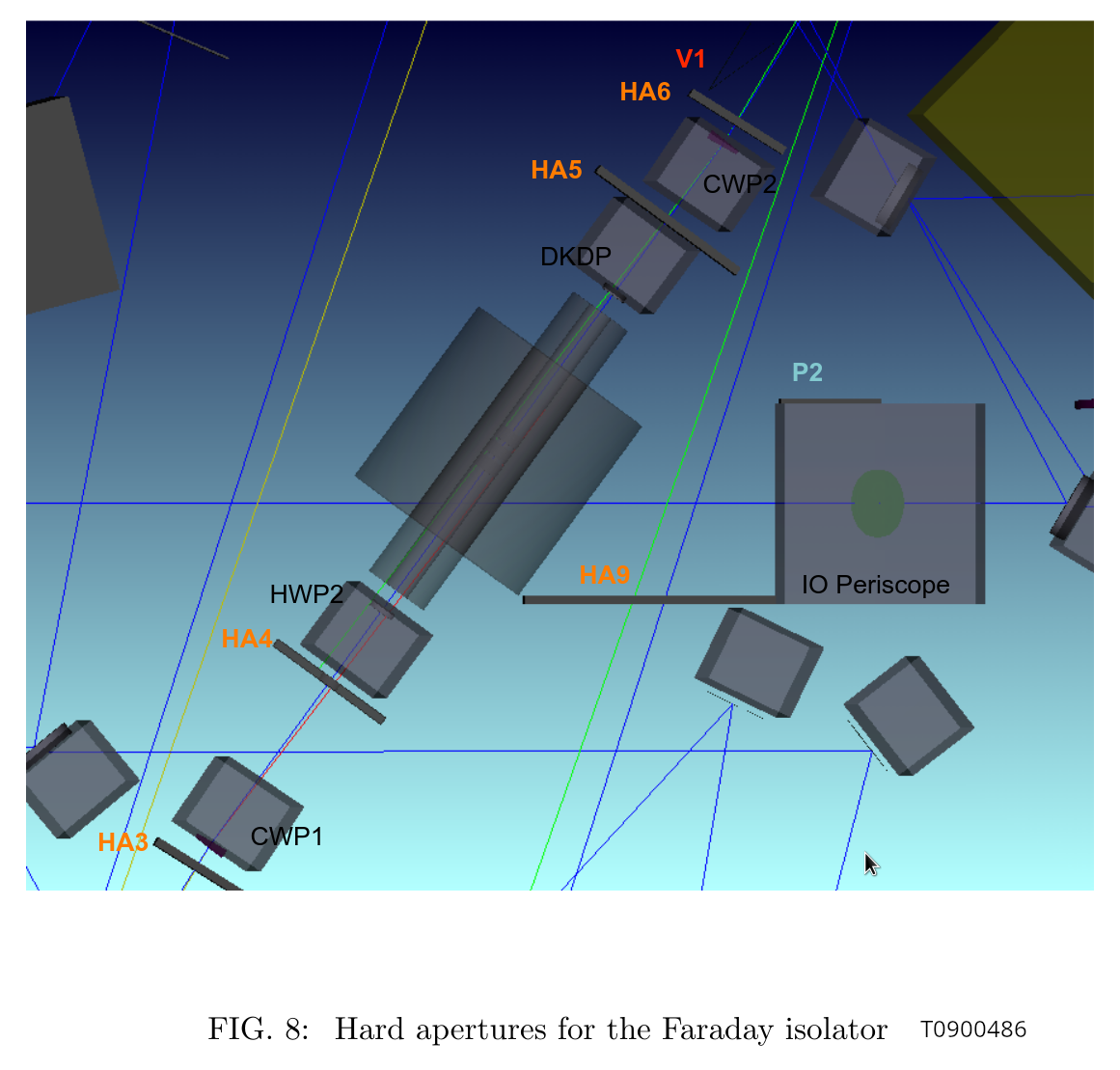
(I learned from T0900486 "IO Stray Light Analysis and Baffle Design" that the IFI input baffle is called HA3, IFI output baffle is HA6, the baffle right in front of IM4 is actually supposed to be a pair of HA12-a and HA12-b but there's only one baffle which I suppose is HA12-a, two-hole baffle for ISS array is HA11, and the last IFO REFL before the beam leaves HAM2 is HA13.)
The beam spot on this baffle was OK before we did anything to IM1 on Tuesday (IFIinput_before.jpg). It's low and toward +X, but nowhere near clipping.
This baffle is right in front of the calcite wedge that deflects the IFO REFL beam away from the incoming beam path from IM2 (HA3_calcite_wedge.png). The lever arm from the wedge to the baffle looks to be an inch or so at most. Hard to imagine that the REFL is clipped while forward going beam is not, but the scattering goes away when I block the beam between PRM and IM4.
The reported "IFO REFL beam clipping" on this baffle is either because the PRM is not retroreflecting, or maybe it's some kind of ghost beam produced from the PRM reflection somewhere.
If we establish that the main IFO refl is NOT clipped when PRM retroreflects, we don't have to worry about this baffle too much (though ghost beam is still a problem).
We will have to bring a card with a hole to make sure that the beam is retroreflected as good as we can.
FYI, IFIinput_aftercentering.jpg shows the same baffle after we made a huge change in IM1.
We don't have any good view of that baffle so it's hard to assess, and we forgot to check it before making changes to IM123.
However, given how small the change was on IFI input baffle, we don't expect that it was very bad before. We'll have to revisit and confirm.
As of now, the measured beam position in front of MC mirrors are as follows this. For measurement points, see mc_beampos_measurement_cartoon.jpg. The height is pretty good for all. MC3 is great horizontally too. Beam spot on MC2 and MC1 are both shifted in -Y direction. MC2 by 3.6+-1mm, MC1 by a couple +-1mm.
| Height from ISI measured [nominal] | Horizontal shift in Y direction from the nominal beam position | |
| MC1 | 154.3 +- 1.3 [155.5] | -1.9 +- 1 |
| MC2 | 167 [166.7] | -3.6 +- 1 |
| MC3 | 154 +- 0.5 [155.5] | +0.3 +- 1 |
Horizontal positions were determined by covering half of the beam with a vertical hard edge (ruler etc.) and then measuring the position of the edge relative to the neighborhood screw holes using a small ruler, and then using the drawings (D0901088, D901089, D0901099) as well as other IO documents (e.g. T0900486) to figure out the nominal beam location. As an example of tedious work done, see ham2mc1.png. Due to the way it was done, we cannot determine the horizontal position of the beam much better than maybe 1/2 of the beam radius. I just put +-1mm error for all measurements. Height numbers were measured off of a ruler, the error bar (if any) is the difference between Rahul's reading and mine divided by two.
What if we move MC2 or MC3 beam spots (or both) to unclip IM4 baffle (HA12)
To get more sense of magnitude of IMC motion relative to the beam motion on IM4, I calculated how much the IMC alignment should be changed to move the beam on IM4 by 3mm in -Y direction (comfortably far from clipping but not enough to center) without moving IMs.
There are many linear combinations of the MC3 spot position and the angle of the beam coming through MC3 that will move the beam on IM4 by 3mm, so I just chose "parallel transport of MC2-MC3 line" (i.e. no angle change of the angle of the beam coming out of MC3), "rotate MC2-MC3 line around MC3" (i.e. no beam displacement on MC3) and something in-between ("rotate around MC2").
See cartoon_IMC_alignment_to_unclip.png (not to scale but the sign of displacement/rotation is correct along the entire path) and IMC_to_unclip_HA12.png (actual calculation). IMC is not the only thing that moves, we can also move IM2, but anyway. In the "parallel transport" case the beam will be move further away from the center of MC2 (remember it was already 3.6+-1mm in -Y direction to start with so the end result will be 6.8+-1mm in -Y direction). OTOH in the "rotation around MC3" case, the beam on MC2 will move by 11mm in +Y direction so the end result will be 11-3.6+-1=7.4+-1mm in +Y direction.
In all cases the beam will likely still hit the IM4_TRANS because the QPD (Excelitas C30845) has a huge 8mm active diameter, but it will likely be completely in one quadrant. So all of these will be bad solution if we believe that the IM4_TRANS position should be close enough.
Note that the "rotation around MC3" case will result in about 1mrad beam angle change on IM4. This needs to be absorbed by IM4 rotation by about 500urad to send the beam to PR2.
It's also worth noting that IM4-PRM HR distance is almost the same as IM4-IM4_TRANS distance.
What if we fix the beam on IM4_TRANS?
Instead of IMC alignment, now let's think about the beam positions from the end point (IM4_TRANS).
Again, assume that we want to keep the IM4 TRANS beam position. We tried two different IMC alignment, and the beam was clipped on IM4 baffle (HA12) after bringing the beam back to the target IM4 TRANS position.
Moving the beam position on HA12 by 3mm in -X direction without changing the IM4_TRANS position means that we shift the beam position on IM3 by about 8mm. IM3-IM4 path beam angle changes by 4.8mrad counter-clockwise. This is an absolutely huge change.
PRM should be moved by 2.4mrad, and 8mm on IM3 is already the radius of IFI output baffle (HA6) so we'll be worrying about clipping there. There seems to be no solution where the beam is far enough from the IM4 baffle (HA12) edge AND the beam is on the same position on IM4_TRANS as in vacuum.
As far as we assume that IM4_TRANS is trustworthy, it's very likely that the beam was clipping or at least very close to clipping on HA12 in O4.
However, if IM4_TRANS path moved after HAM2 was opened (i.e. somebody bumped something), IM4_TRANS position as of now doesn't mean anything. We have to at least grab and wiggle the steering mirror as well as the QPD for that path to make sure that nothing is loose. (I already did that test for MC2 TRANS, and they didn't move.)
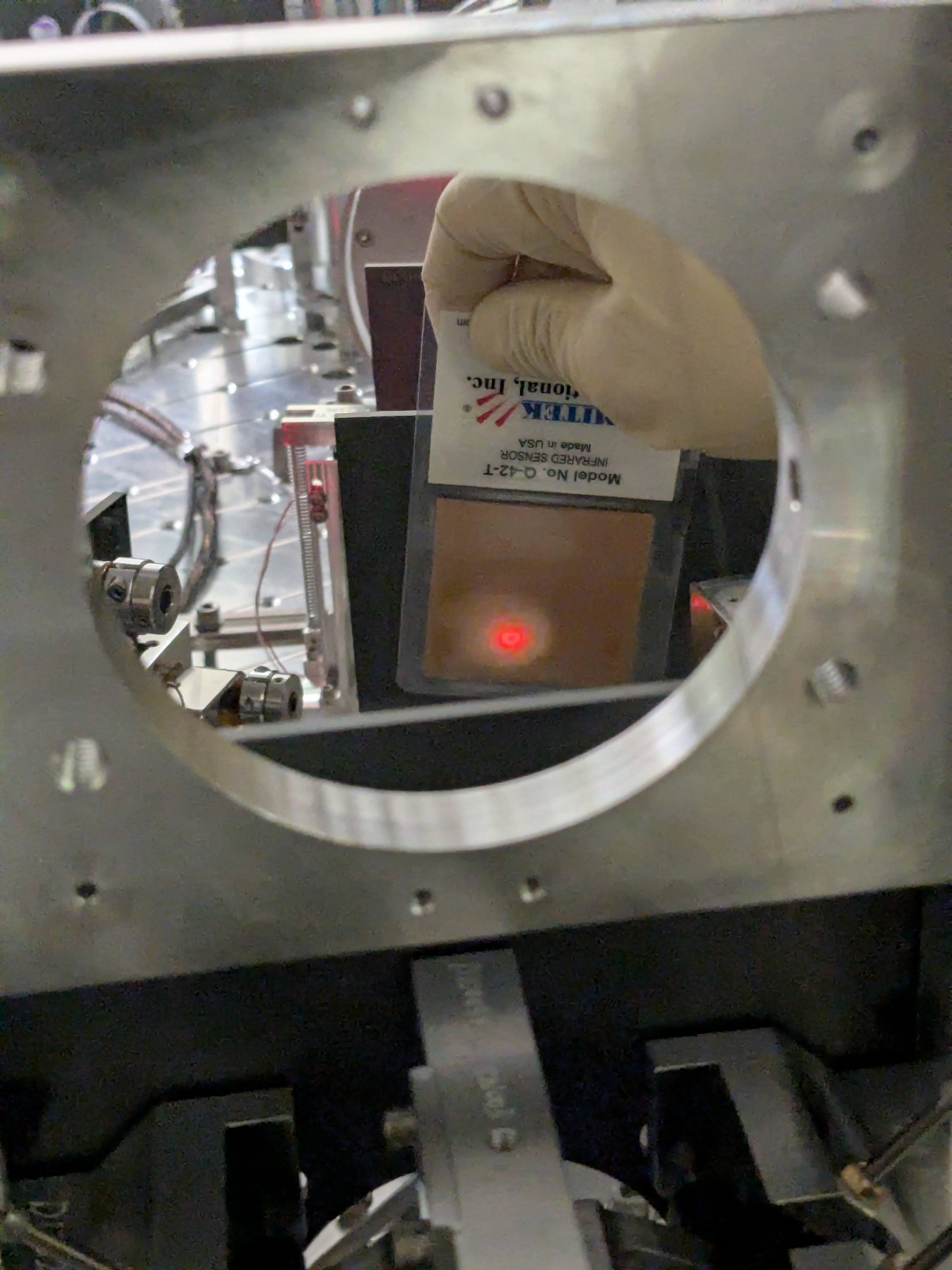
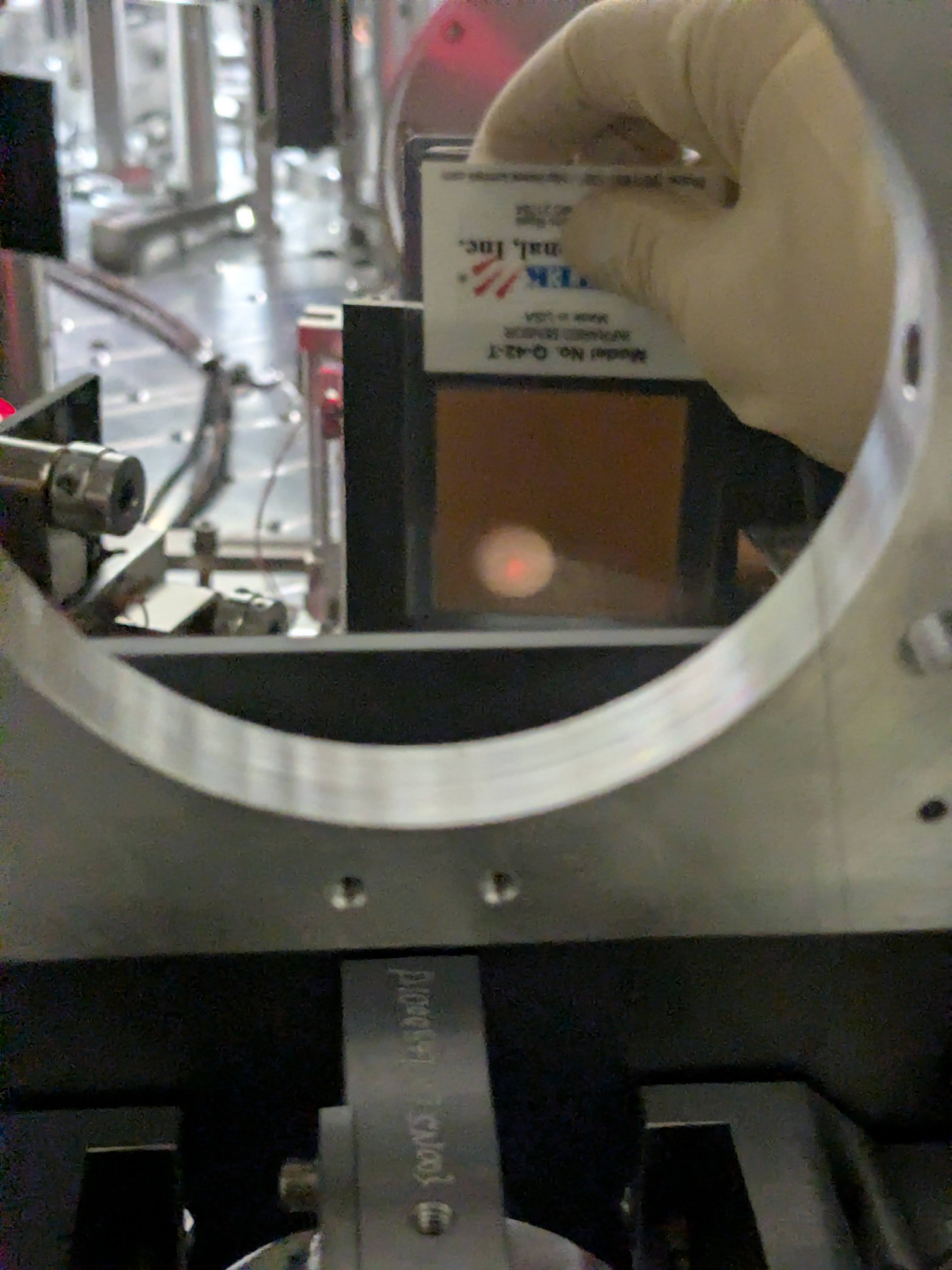


Attached are an example of beam position measurements (in this case MC1).

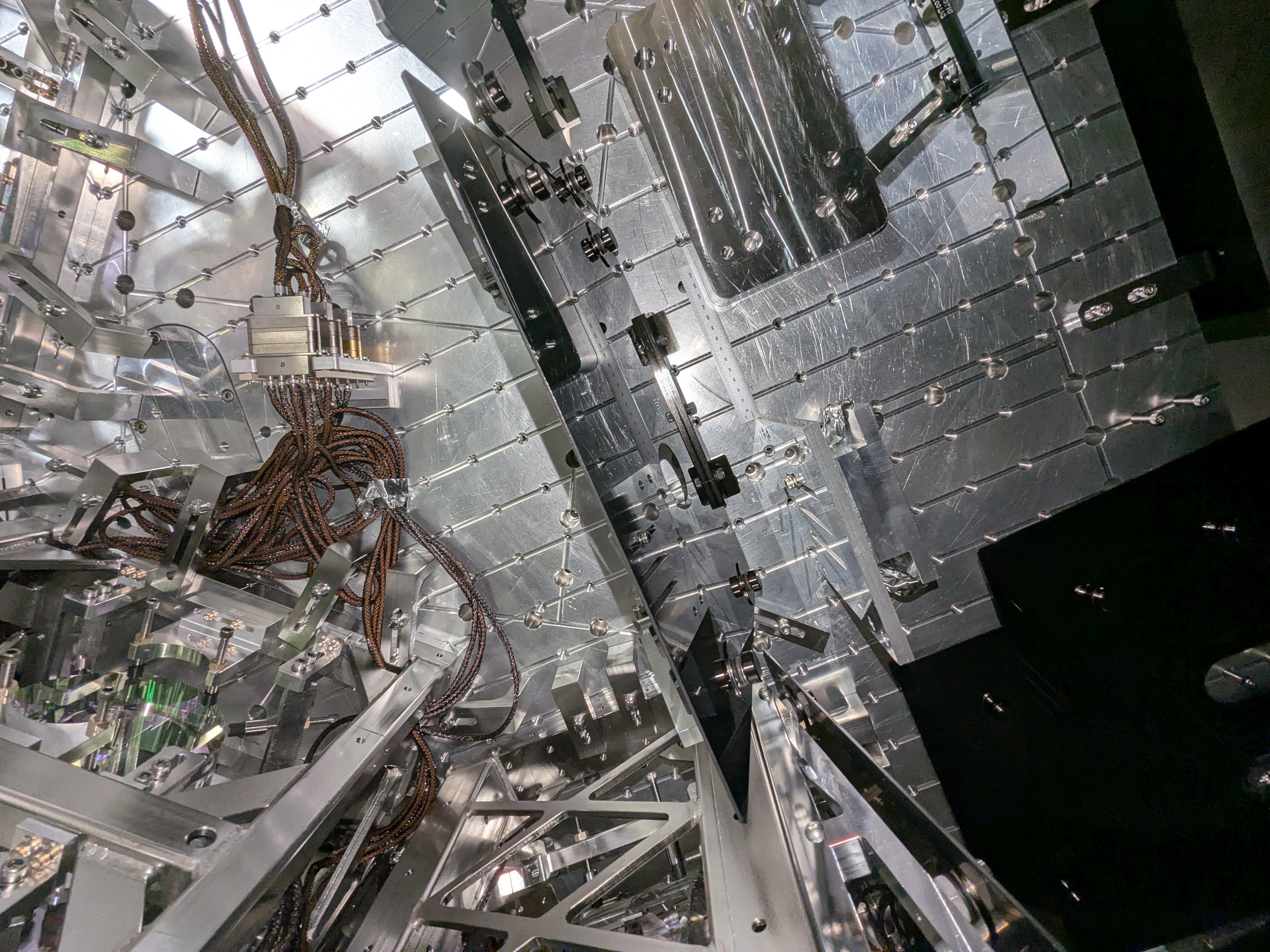
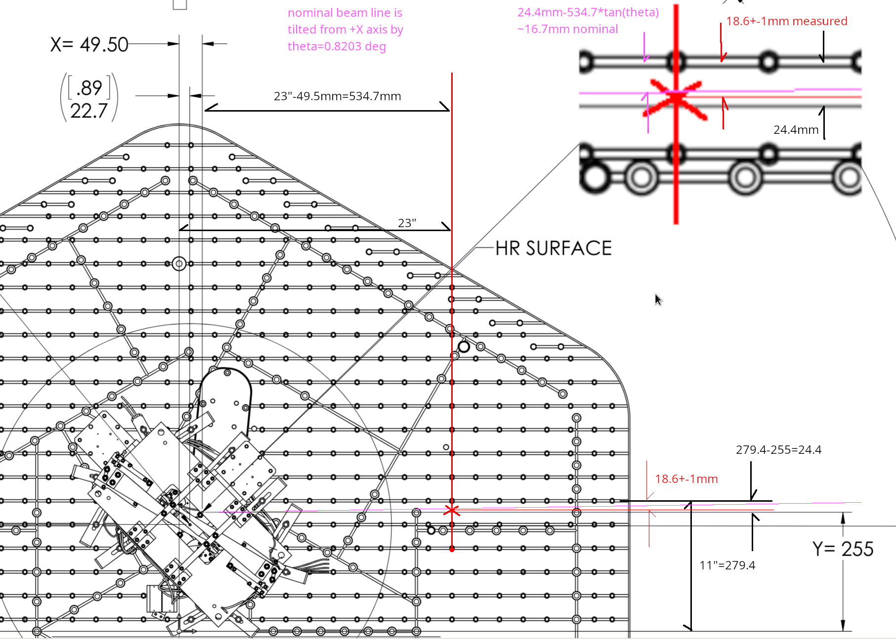
IM4_TRANS path optics (pickoff for the ISS path, pico for IM4_TRANS centering) as well as the IM4_TRANS QPD itself seemed to be firmly attached to the pole and the ISI table. I grabbed them using my hand and wiggled and they didn't move at all.
The beam is level between IM1 and IM4 and then goes up toward PRM, but I cannot easily find how much. So here's a quick note.
| MC3 | IM1 | IM4 | PRM AR | PRM | |
| Height [mm] | 155.5 | 155.5- | 155.3 | 158.8 | |
| Angle [rad] of the exiting beam relative to the horizontal plane | level | 8.5m | 628u | 628u |
Nominal height of MC1 and MC3 center is 155.5mm (D09010088, D0901089). IM1 beam height should be pretty close though MC2-MC3 line is not level.
The beam from PRM HR to PRM is tilted up by 0.035966 deg = 628urad (I'm using the PIT angle of PRM itself in D0901920 rather than reading the coordinates of PRM and PR2).
PRM has 1 degree vertical wedge (D0901172), the bottom being widest, so the beam is tilted up from IM4 to PRM AR by ~(n-1)*1deg = 0.4497 deg relative to the PRM-PR2 line, n being the refractive index of fused silica for 1064nm (1.4496).
The beam from IM4 to PRM AR is therefore tilted up by (0.4497+0.035996) = 0.4857 deg = 8.5 mrad relative to the horizontal plane.
PRM center height is 158.8mm nominal (D0901090) and the distance from PRM AR to IM4 is 415.9mm (T0900486), so the beam height at IM4 should 158.8-415.9*8.5mrad = 155.3mm, which is good enough of an agreement with MC3 height.
FYI I measured the IM4 baffle height this morning and it was (206+104)/2 =155mm, so the baffle height should be correct. (The beam is low on that baffle though YAW is the worse problem than PIT.)
[Keita, Rahul, Elenna]
Today I moved IM2 and IM3 to bring the beam back to our reference position on IM4 trans QPD and center it on ISS QPD after Keita's move of the mode cleaner mirrors in 90259. This requires some iteration back and forth on both suspensions.
Our desired positon on IM4 trans is P = 0.22 and Y = -0.06. On ISS QPD, it is centered, so P=0 and Y=0.
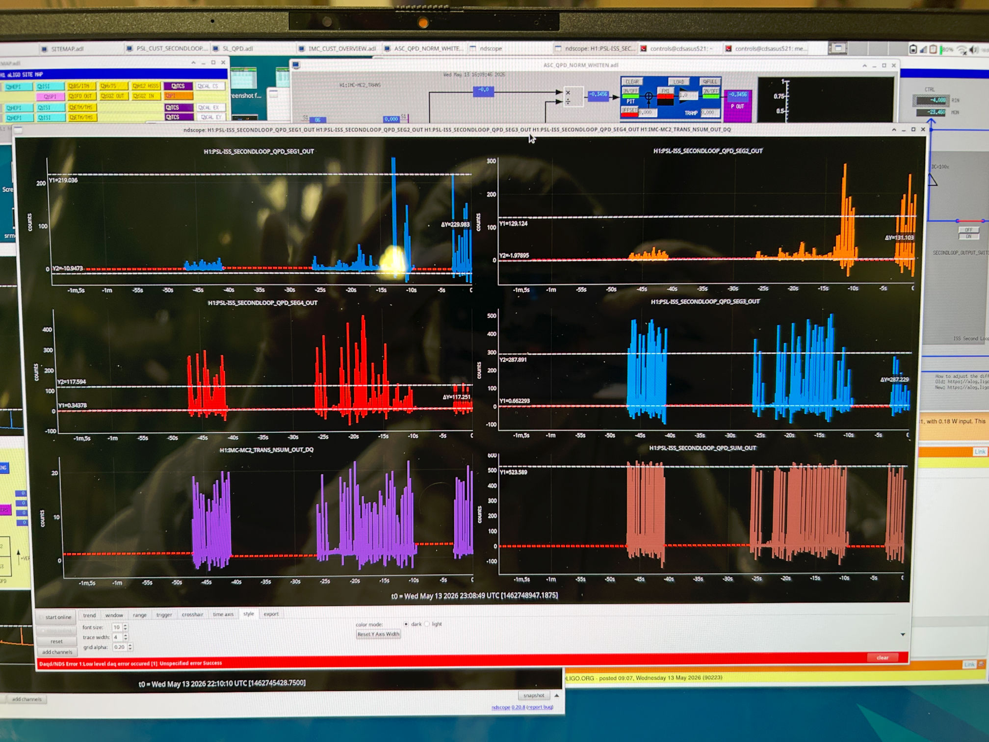
We are driving MC2 in length, so the mode cleaner is flashing, and there are bright flashes on the QPDs. I am pausing ndscope on a flash and measuring the height of the peak in the fast channel and calculating the pit and yaw position from each QDP segment.
| Start | End | ||
| IM2 P slider | 765 | IM2 P slider | 810 |
| IM2 Y slider | -187.7 | IM2 Y slider | -88.7 |
| IM3 P slider | -560.7 | IM3 P slider | -614.7 |
| IM3 Y slider | 320 | IM3 Y slider | 385 |
| IM4 trans PIT | 0.390 | IM4 trans P | 0.268 |
| IM4 trans YAW | 0.450 | IM4 trans Y | 0.010 |
| ISS QPD PIT | -0.379 | ISS QPD PIT | -0.059 |
| ISS QPD YAW | -0.455 | ISS QPD YAW | 0.08 |
Unfortunately, this still results in clipping on the baffles Keita notes above, so we will keep going.
At the nominal IM4 trans position, yaw is pretty well centered. I then moved IM2 to both edges of IM4 trans QPD.
I changed the IM2 yaw slider to -250.7, which brought the yaw position on IM4 trans to 0.85. This made the clipping worse.
I changed the IM2 yaw slider to 90.3, which brought the yaw position on IM4 trans to -0.88. This was still not good enough to fix the clipping on the baffle.
By making a very large move to IM2 yaw slider value of 710.3, this centered the beam in the IM4 baffle. This is a ~800 urad move according to the osems and slider. The IFO REFL beam is still clipped.
I undid the 800 urad move, so the IM2 yaw slider is back to -88.7 for now.
Keita and Rahul went out to measure the position of the beam on MCs 1,2 and 3. We think that we need to make a move of these three mirrors to see if we can unclip the beam on these baffles that way.
We want to note that the positive yaw move of IM2 corresponds to unclipping on the IM4 baffle, this is consistent with the beam motion observed in chamber in the -X direction. However, this is contradictory to the sign on IM4 trans QPD, which was moving to negative yaw when we did this move. We suspect that the segment defintion must be wrong somewhere.
Keita will say more later once we have a chance to analyze the positions in chamber.
To clarify, the slider values of IM2 and IM3 are left at the "end" positions on the table above.
I trended the power measured at IM4 trans compared to the IMC input power for the entirety of the run. Some notes:
Because of this recalibration, I decided to compare both the IM4_TRANS_INMON and IM4_TRANS_OUT16 to IMC-PWR_IN_OUT16
FM10 in the IM4 trans filter bank is a factor that Craig and Georgia determined in the alog linked above, 4.606. I trended the inmon channel and multipled it by this number, ignoring other calibration factors present in the filter bank.
Therefore, the plotted ratio of IM4_trans [IN, OUT] / IMC power IN will help us understand how the power at IM4 trans changed throughout the run, like perhaps if the amount of clipping on the way to IM4 has changed.
I am comparing the ratios of both IM4 trans IN and OUT just in case we get confused by the changing calibration of the diode. I took an hourly median of these channels so we are not confused by random variation and masked the times to only show when IMC lock was either in state 100 (locked) or 70 (ISS ON).
Overall, the amount of power arriving on IM4 trans has definitely changed throughout the run.
Notably, during the vent between O4a and O4b, the amount of power measured at IM4 trans dropped. We chose not to move the IMs, and instead Sheila picoed to recenter on IM4 trans, linked above. Another power drop occured again during O4b. This time, we moved IMs to fix it. At the start of O4c is when Sheila and I recalibrated the diode, hence the disagreement with IN and OUT channels.
The second plot attached shows how the pitch and yaw on IM4 trans has varied alongside the power.
Based on what Keita can see happening in the chamber with baffle clipping, it is possible that during these alignment shifts, the amount of clipping in HAM2 on the IO baffles was changing, so the amount of power making it to IM4 trans and the amount of power going into the IFO was changing.
Specifically, I want to emphasize that with Craig's integrating sphere measurements in HAM1, we assumed that all loss between HAM1 and the PRM in HAM2 was known, i.e. loss from the IFI, etc. However, if there was additional loss on that path that changed with input alignment shifts, that would explain the apparent IM4 trans power changes during O4. Notably, Sheila and I recalibrated IM4 trans in O4c because after we fixed the input alignment in late O4b, we got more power on IM4 trans than we had gotten all run (see the jump around day 600 on the attached plots). I thought this was not physically possible, so we adjusted the calibration. Perhaps instead, we changed the amount of clipping in HAM2, giving us more light on the PRM than we had seen all of O4.
This may also help explain some of our arm power measurement mysteries if we actually had less input power than assumed.
I just want to add a clarification that we have been trying to replicate the alignment onto IM4 trans QPD, so we are trying to align to the previous pitch and yaw position. However, for O4, the beam was nearly falling off the ISS QPD, so we don't want to replicate that alignment (the pitch and yaw values on ISS QPD were like +- 0.9). We have decided to go with centering the beam on ISS QPD, especially since we have adjusted the ISS pico mirrors to find that alignment.
Clipping on IFO REFL baffle is gone.
The problem of IFO REFL beam clipping by the last IFO REFL baffle in HAM2 (see alog 90251, especially this picture) seems to have been caused by a huge PRM change in the PRM alignment sliders made on Monday May/11/2026 past 1700 local time (that none of us knew/remembered/understood).
Once Sheila reverted PRM back to March/2026 alignment, changing the IFO REFL beam path (but not the alignment into ISS path), IFO REFL was not clipped any more even though it looked low on the baffle (IFOREFL_baffle.mp4). LSC and ASC REFL sensors on HAM1 ISI saw the flashes right away without any adjustment of RMs, and the flash peaks were already reasonable. According to Sheila, compaing to a time when DRMI was acquiring in November:
All of these were a good sign.
Forward-going beam into the IM4 is clipped by the baffle in front of IM4, and the IFO REFL beam is clipped by the baffle at the -Y edge of the IFI.
Unfortunately I've found that there were two other clipping points that I must have missed yesterday using IR viewer. See clipping.png, sorry for a blurry through-IR-viewer picture shot from the distance. Go back to HAM2layout_annotated2.png to figure out which baffle is what.
There's a baffle in front of IM4 between IM4 and IM3, and the forward-going beam is slightly clipped at the +X edge of that baffle.
Also the IFO REFL beam is clipped by the baffle installed at the -Y edge of the IFI. I know this is IFO REFL because the bright spot goes away when I block the beam on PRM by a sheet of aluminum. I cannot quite tell from the picture which edge of the baffle is clipping, but I think it's also +X edge.
In the past, when PRM spot position was measured with full IFO, it was like a mm off according to Sheila, so it's hard to imagine that the beam was clipping on the baffle in front of IM4.
Changing IMC alignment (trial 1, didn't fix clipping).
We decided to back off the changes we've made for MC1, 2 and 3 since Monday and revert back to in-vac March alignment. If we have to make a huge adjustment to JM3 to follow the IMC, maybe the beam coming from JM3 is suspect (which means that the MC2 trans path is somehow suspect too).
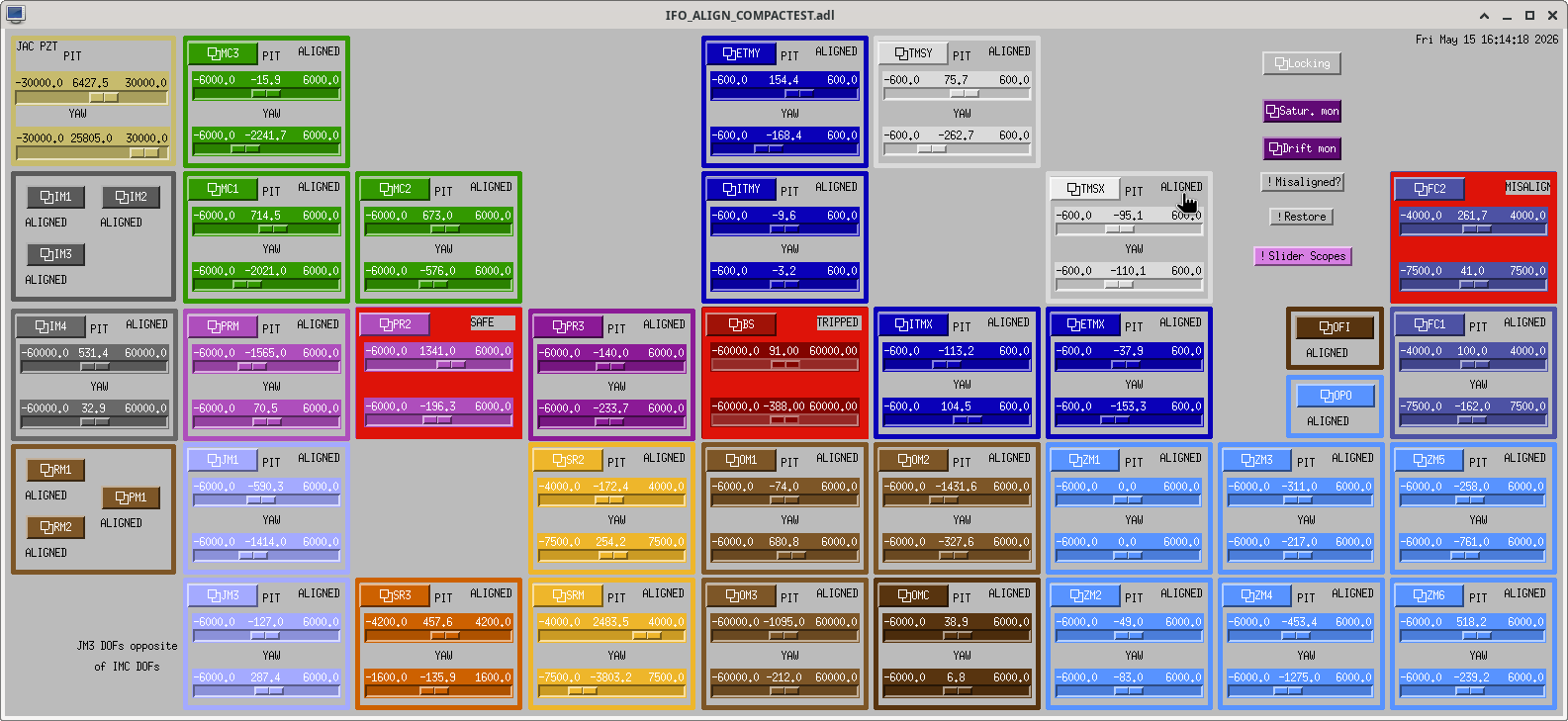
Before I did anything, the starting point was captured in alignment_2026-05-15_16-14-21.png.
MC1/2/3 was reverted just based on slider values and not using OSEM readings as per alignment_2026-03-18.png.
Then JM3 was adjusted in PIT and YAW to give the maximum transmission measured in IM4_TRANS_NSUM. Actually I didn't move JM3 as much as I expected.
That alone couldn't recover a good 00 mode flashing so I moved MC2 and MC3 to follow the input beam. MC2 moved back closer to the position this morning.
After that I felt as if it was somehow easier to optimize further using MC1 as well as MC3, thinking that it would be a minor adjustment but somehow ended up moving MC1 by a large amount after iterations.
My end point is captured in alignment_202605151726_sliders.png.
Without IM3 and IM2, the beam was still on IM4_TRANS as well as ISS QPD, the flashes were good, so I looked at the clipping on the baffle in front of IM4 as well as the baffle at the -Y edge of the IFI, and they were still there. IFO REFL baffle was still not clipping.
Will have to think about what these all mean.
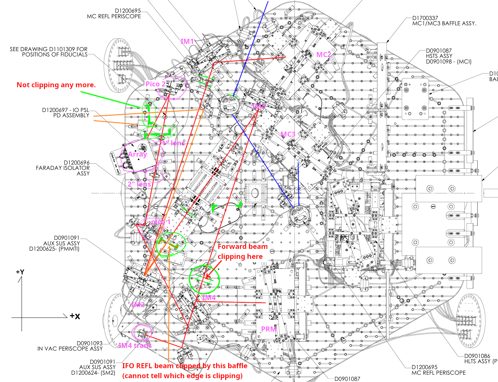
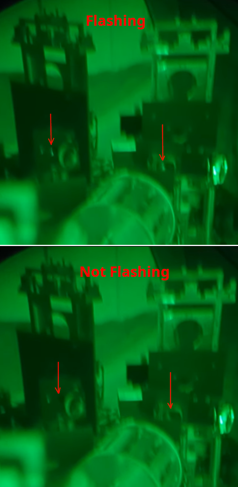


Good news is that we're done with the alignment of the ISS path. Pictures and details are to follow.
Then I reinstalled the last IFO REFL baffle right in front of the HAM2-HAM1 septum window. (The baffle was removed after marking the exact position using three temporary dog clamps on the ISI on day 1 because it was in the way, I was supposed to record that in alog 90158 but forgot. I'm absolutely sure that the position of the baffle was restored within 0.1mm of the original position.)
Bad news is the IFO REFL was clipped on that baffle. 00 mode flash isn't clipped that much but horizontal modes certainly are. That was not THAT surprising because the IMC alignment was/is not great (see my comment 90224). This looks to me that the uncontrolled degree of freedom of the IMC is wrong regardless of the reason why a huge alignment change had to be made to center the MC2 TRANS QPD.
Good news is the ISS path alignment is not impacted by that, at least greatly, because we made sure that the beam hit the right location of IM4 TRANS as well as ISS array QPD before we did anything in the ISS path. Note that the baffle clipping the beam is not in the ISS path.
In other words,
However, since we don't want to revisit HAM2 once we close it, I'd like to understand what's going on for the IMC/IFO alignment.
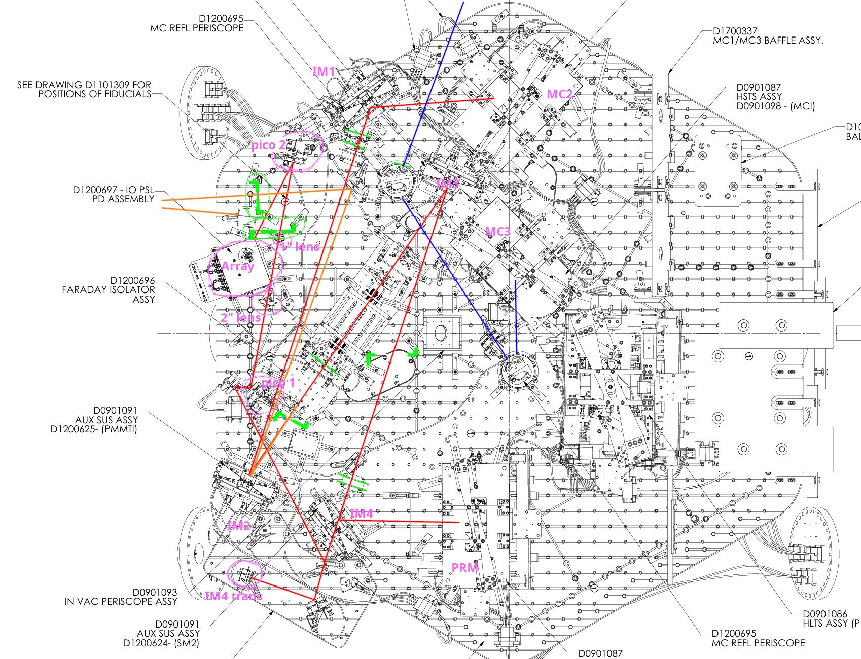
For location of things, refer to HAM2layout_annotated.png. Blue line = IMC reflection. Red line = IMC transmission. Orange line = IFO REFL rejected by the IFI. Green things are baffles (two-hole baffle and the last IFO REFL baffle are circled in green).
The alignment status at the start of Thursday morning:
The beam was very high on the two-hole baffles but was OK on the input hole of the ISS array. See alog 90237, see this picture as well as this, and this video. This just meant that we were shooting down the beam from the 1" lens toward the center of the array QPD.
Work done on Thursday:
We moved the beam down using the two pico mirrors such that ultimately the beam goes through the center of the input hole of the array and reasonably centered on QPD.
Detailed procedure was:
We have found no unexpected behavior here, I was surprised that the process was easy and things made sense given the difficulty people had in the past to improve alignment of the array in vacuum with the old unit. That's probably because the beam was already clipping back then.
The only thing was that the YAW actuator of the second pico mirror didn't have much range to start with even before we moved anything. At some point it didn't hit its end of the range but was close (2nd_pico_position_before.jpg). Since we need a healthy headroom for adjustment both ways, I relieved the pico by mechanically rotating the pico mirror assy (2nd_pico_position_after.jpg).
IFO REFL beam was clipping on the baffle:
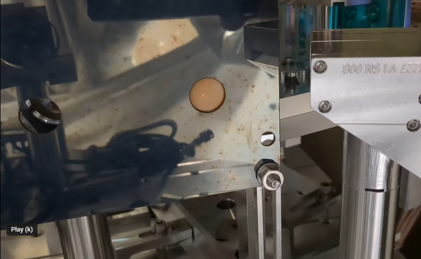
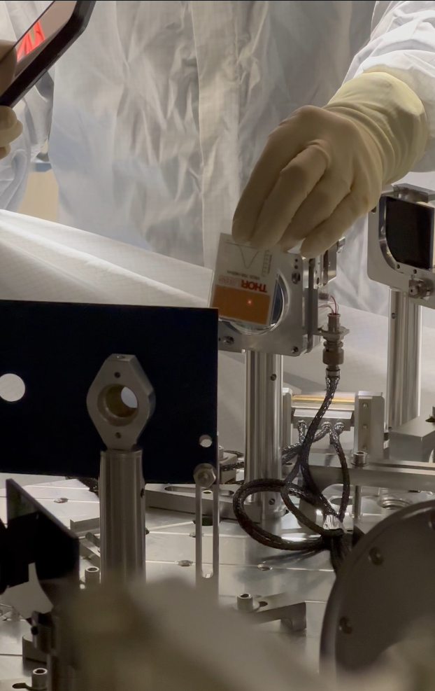

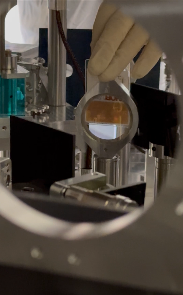
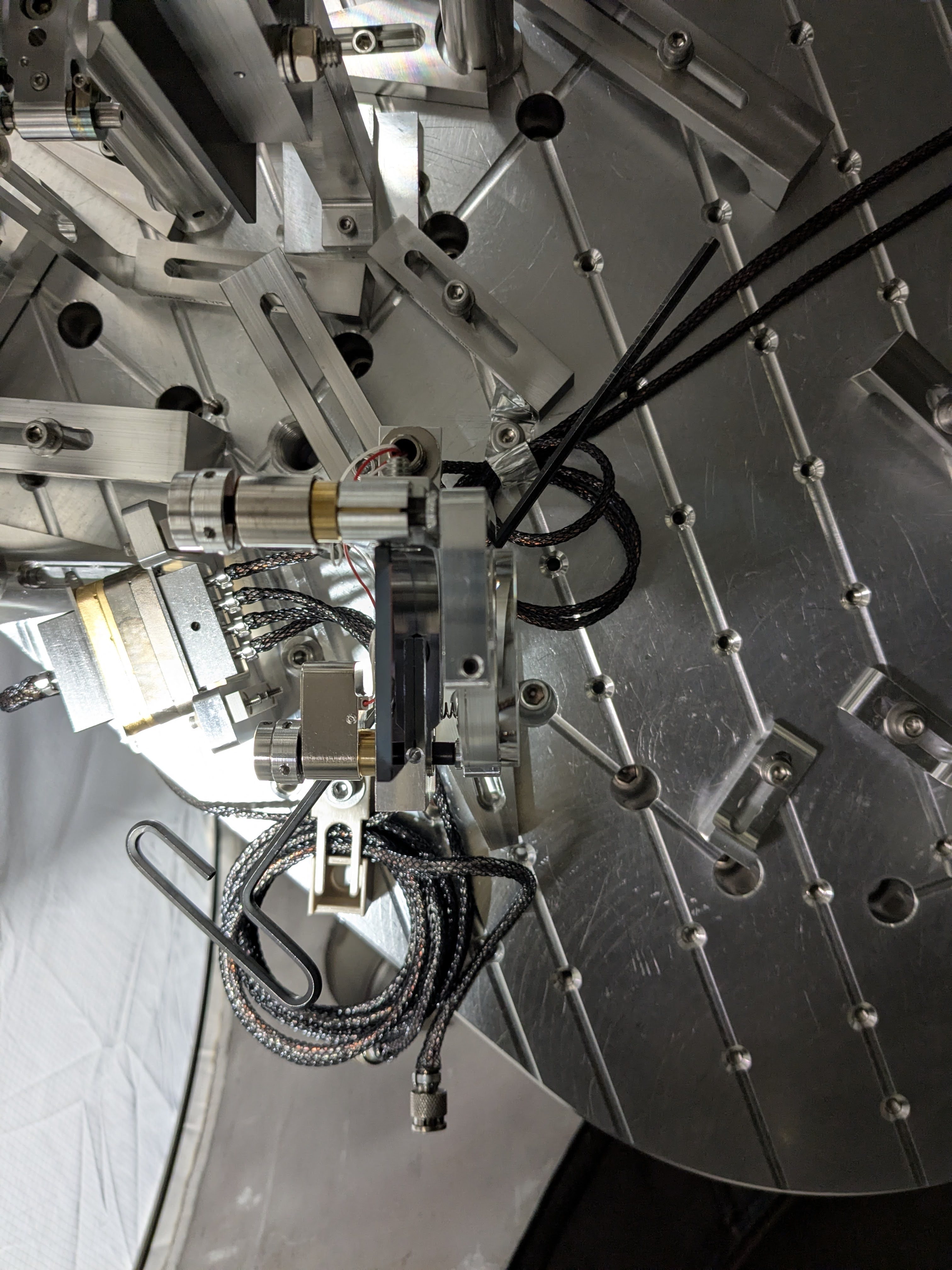


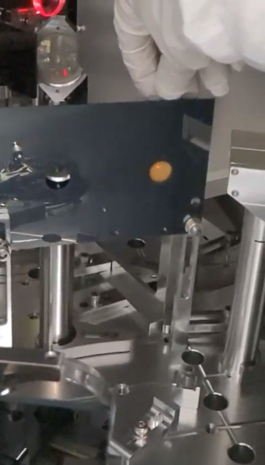
Following yesterday's alog 90219:
At this point I and Rahul checked the beam positions in HAM2. Some things to note:
We proceeded to swap the ISS array unit.
At this point we saw flashes on QPDs as well as array PDs right away. INNER as well as OUTER SUM flashes were both about 0.06 (in the old unit it was 0.03 for OUTER but INNER was much smaller).
We started trying to center the QPD using the first pico mirror. Since pico driver is temporary unavailable (IOT2L is moved away) Rahul turned the pico manually while Elena looked at the laptop screen to monitor flashes in the individual segments. We managed an OK job (arrayqpd_centered.jpg) and checked the beam spots again.
The baffle height might not be the same as the lens height and/or the ISS array input hole height, but otherwise it seems that we're shooting down the beam from the 1" lens to the ISS array. We'll check if the lens, baffle and the array are all at the same height or not, and decide how to proceed.

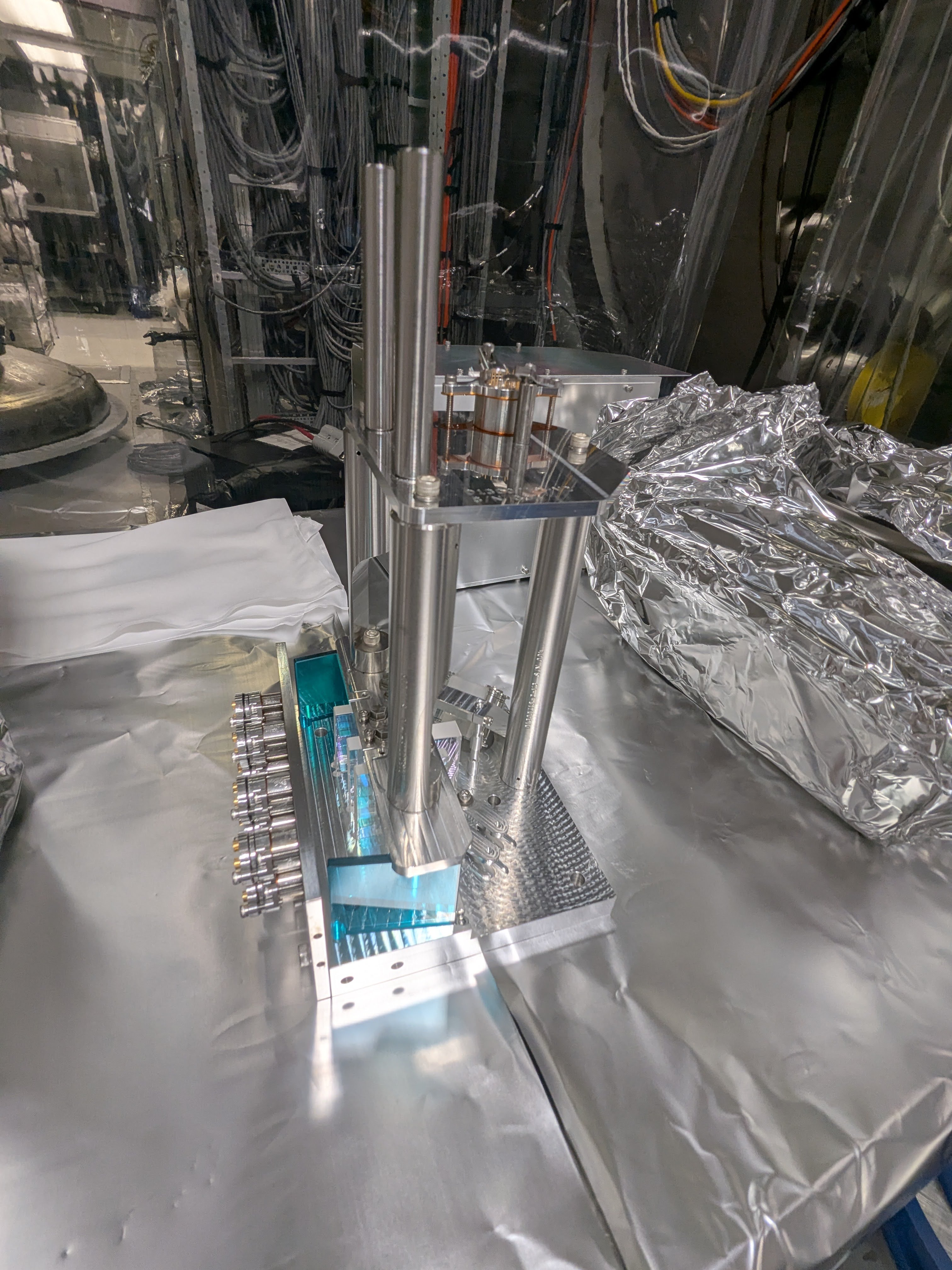
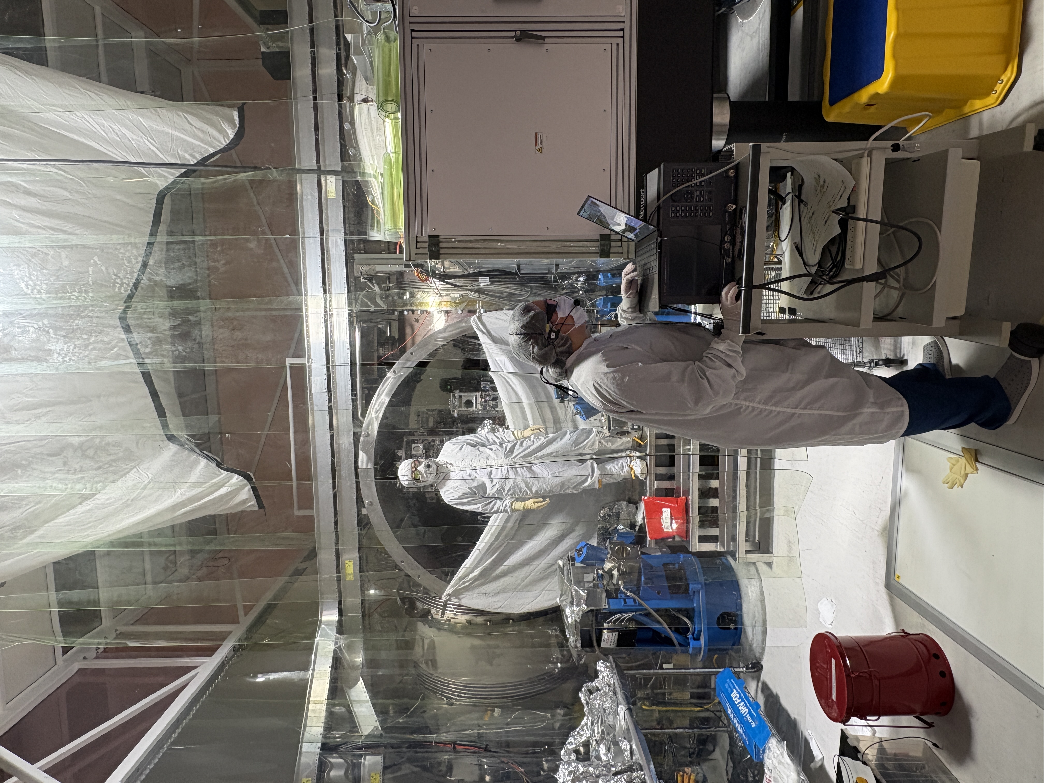
1st: Rahul is disconnecting the QPD cable.
2nd, 3rd (photo by Betsy): Rahul in chamber (me outside).
4th: Old unit was extracted. This is S1202971.
5th: New unit (S1202965) to the left, old one to the right.
6th: Rahul after successfully connecting up the new unit in chamber.
7th (photo by Betsy): Elenna (front) is checking the QPD centering, Rahul (a shadow in the back in this photo) is manually moving the pico mirror from -Y door, and I'm somewhere inbetween just observing the two doing a good job.




epo tagging for photos!
Attaching two pictures in reference to Keita's comment above - "The beam was very high on the left hole of the two-hole baffle (Rahul has a good pic), high on the right hole (right_hole_after_new_array_QPD_centered.mp4)"
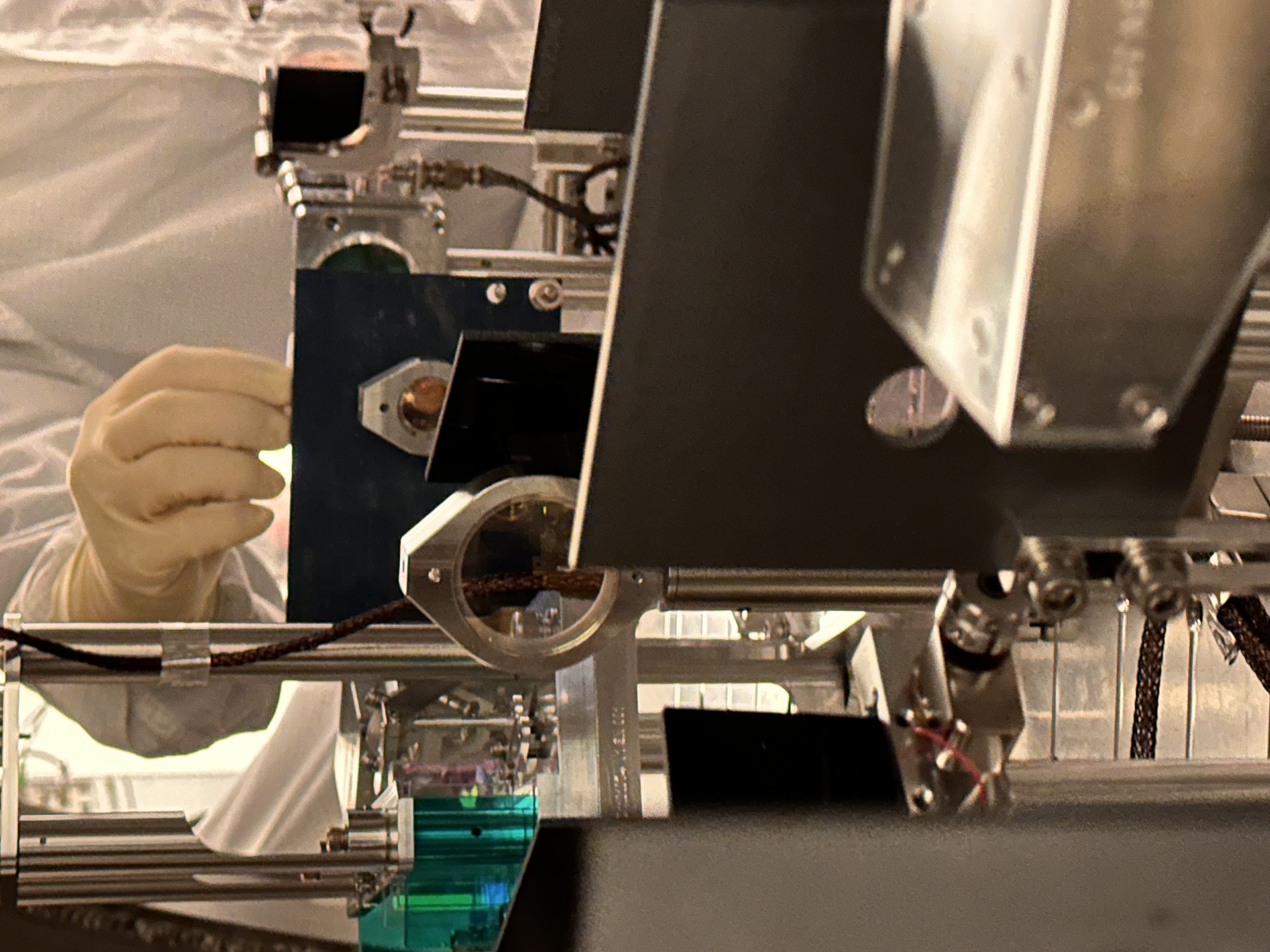
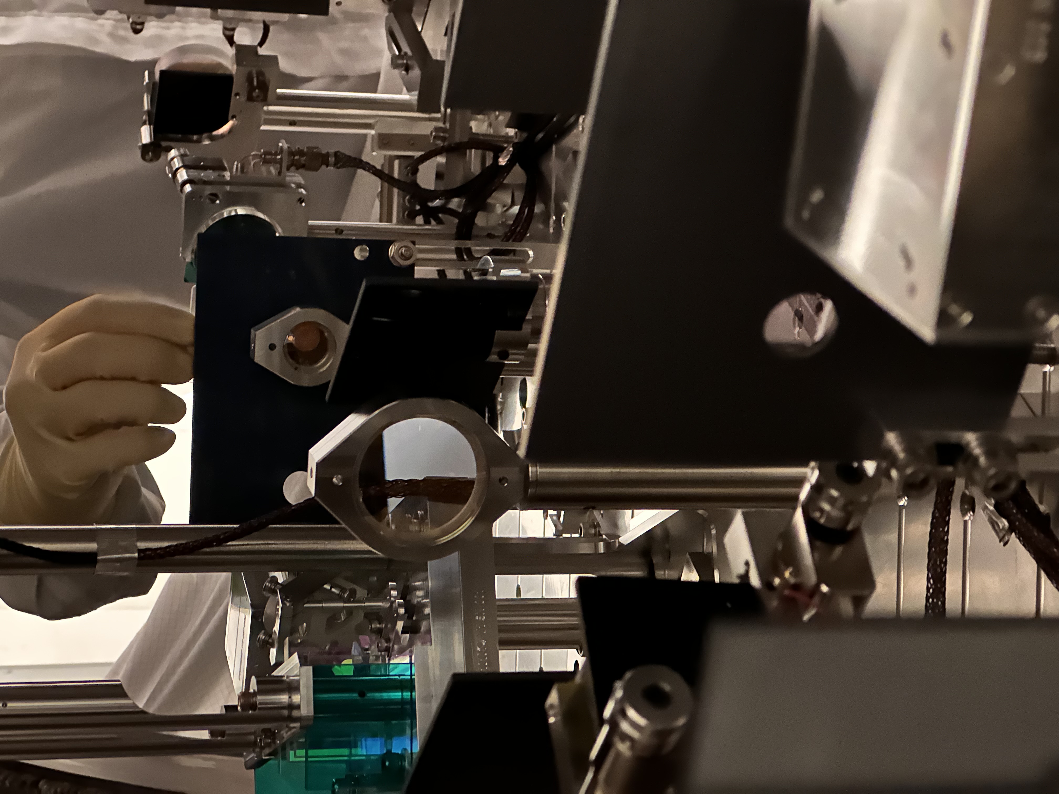
We concluded that the height of the baffle and the array unit are both correct, the beam is really too high on the 1" lens and we're shooting down from there to the QPD. (This should have been the case for a long time with the old unit. Right after the new unit was installed the beam was on QPD and the beam stayed on the QPD, the diameter of the QPD is 3mm, i.e. we haven't made any huge change on the height of the beam at the left baffle hole.)
With this information, what we'll do next is to gradually bring down the height of the beam on the left baffle hole using the first pico mirror, and use the second pico mirror to bring the beam back on the QPD, until the beam line into the array becomes level-ish with the ISI surface. It doesn't have to be perfect but we don't want to be this much tilted.



Restored the alignment sliders for IM2 and IM3 back to Monday values ([IM2P, Y] =[765, -187.7], [IM3P, Y]=[-560.7, 320]).
Measured the flashes. Chose the flash that gave the MC2 trans sum maximum power, which in general agreed with IM4 trans sum max but didn't with ISS QPD nor array PD inner sum nor outer sum.
Anyway,
PIT and YAW numbers were after normalization divided by (seg1+2+3+4), not by SUM, so there's a small difference but that doesn't matter at this point.
IM4 TRANS and ISS QPD PIT and YAW are broadly in agreement with Jenne's alog 90206 i.e.
I haven't compared the ISS Outer SUM with March 2026 when IMC was locked with 2W. Somebody check please. We'll go into chamber and start checking the beam path.
On March 11 when we locked the IMC at 2 W, the outersum was 0.062. Today, I measured the outersum flashes (relative to the dark noise) to be 0.031, with 0.18 W input. This means our alignment into the ISS has improved relative to March.
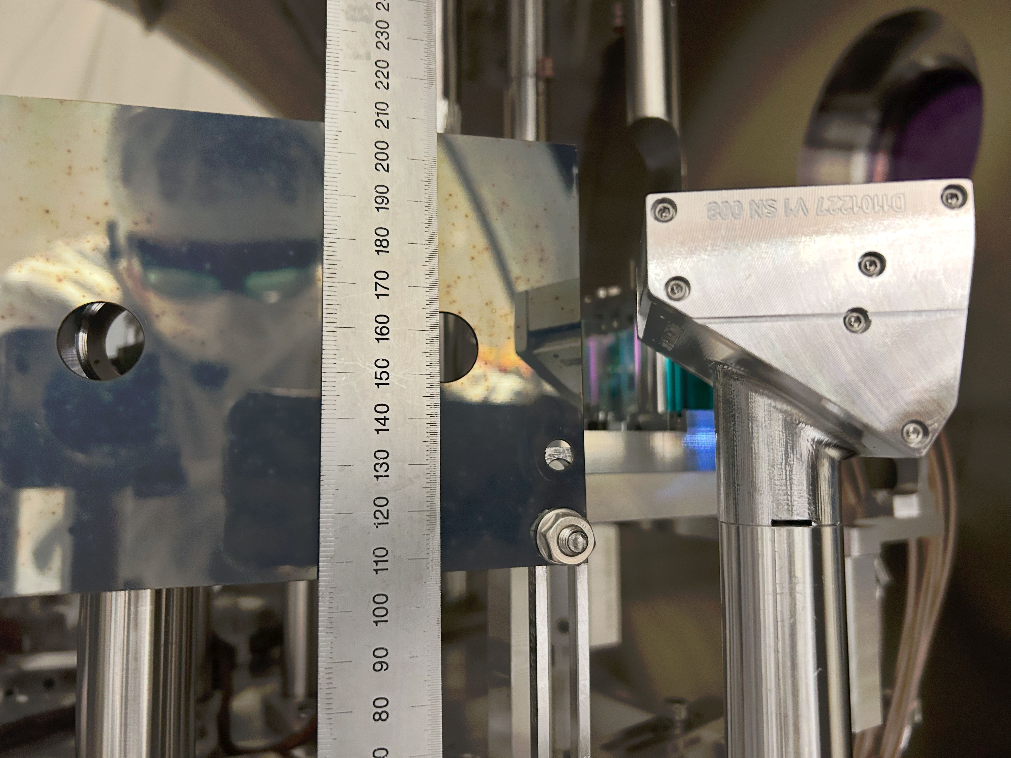
I went to HAM3 to see that the MC2 beam position wasn't crazy. See the first photo, the beam is to the left (+Y direction) relative to the baffle on the HR side but the baffle itself is offset in -Y direction relative to the cage. Green lines are extension of the EQ stop screws to guide your eyes.
I also opened the ISCT1 and moved the mirror in front of the REFL BBPD out of the way and directed the beam to IFO REFL camera (because I couldn't see the beam at all without moting the mirror).
While manually aligning the IMC, we found that somehow things are in such a bad state that the MC2 TRANS SUM decreases when IM4 TRANS SUM increases, and vice versa. Improving the IMC alignment using IM4 TRANS as well as IFO REFL camera made the flashes stronger to the point that we can see 00 mode once in a while. I was also able to see the beam in the ISS path. But MC2 TRANS was nowhere near centered. Attempts to resolve this by incremental changes failed.
We wondered if something behind MC2 was bumped and changed the alignment into MC2 trans. I looked at the path and didn't see anything obvious. The beam transmitted through MC2 was visible using a card and a viewer, it was not clipped by the baffle behind MC2 nor the BS for the beam dump. I could not see the transmission of the BS, though, it was too weak, so I cannot confirm if the steering mirror in front of the QPD was bumped or not.
Elenna started making big changes for JM3 in PIT (to make big YAW changes in the beam injected into IMC, remember that YAW and PIT are flipped between JAC and IMC, IMC WFS takes care of this but that won't help when you're manually aligning JM3) and moving MC2 and MC1 so that the IMC follows the input beam. Repeating this in YAW anShe successfully centered the beam on MC2 trans.
At this point I looked at the MC2 beam position again, see the second picture. Apparently the beam moved in YAW by a few mm to the right (i.e. -Y direction).
Elenna will post which optic was moved by how much in which direction.
Jenne is now trying to put IM4_TRANS and ISS QPD beam position back where they used to be using IM2 and 3.
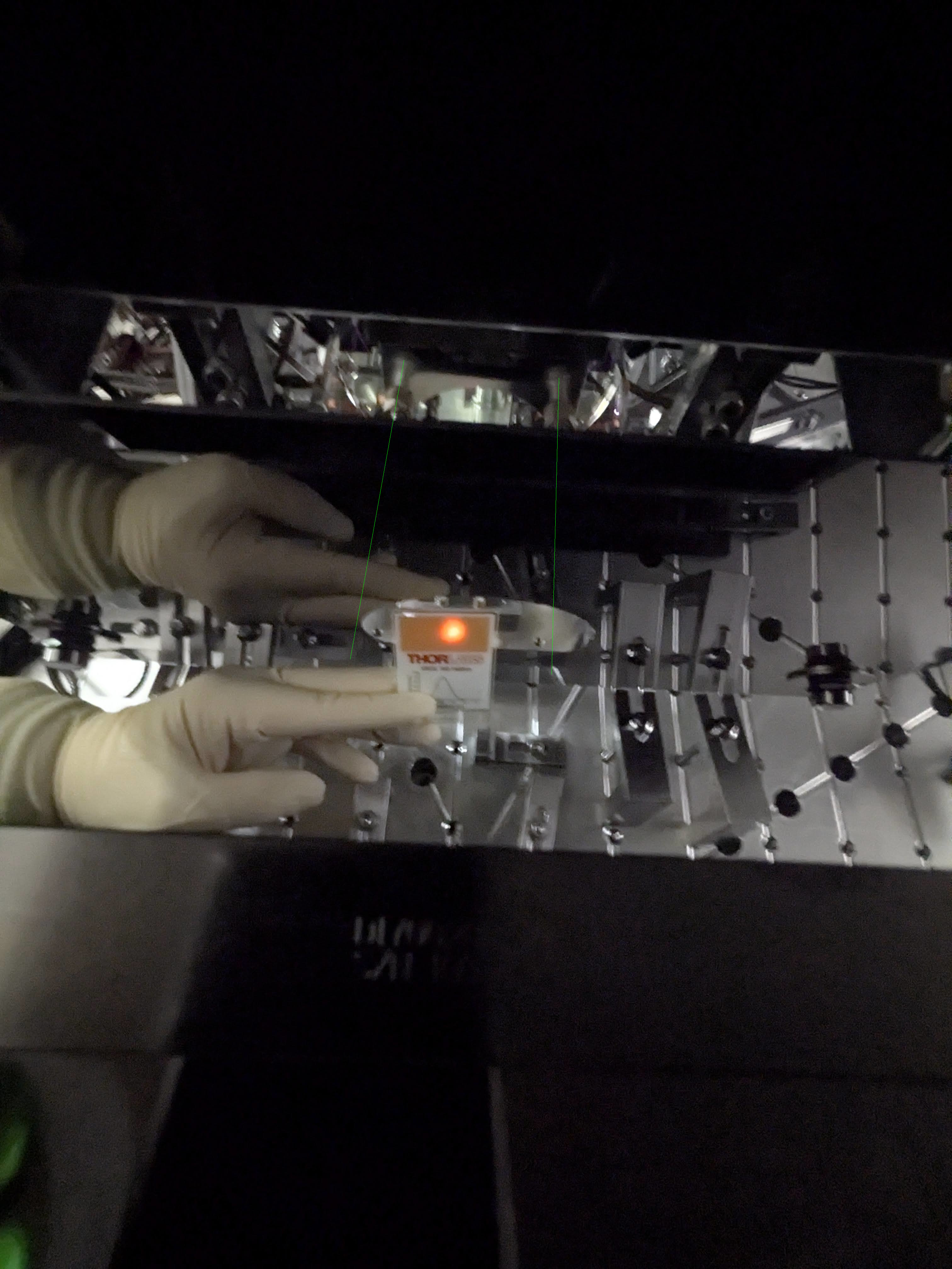


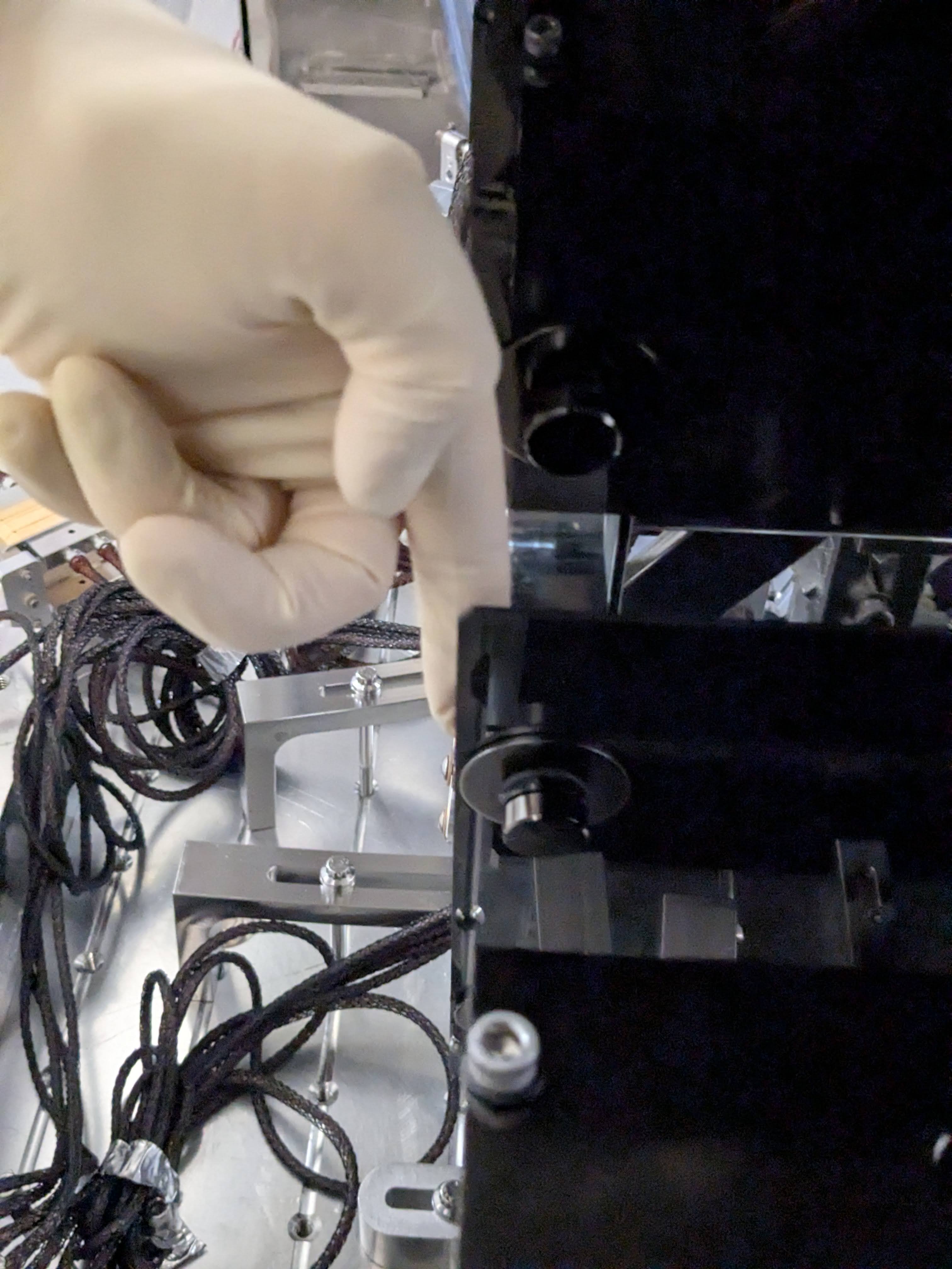
We found that people opening BSC door cover(?) somehow disturbs IMC whether or not HAM3 and HAM2 door covers are on. The IMC fringe becomes super fast and it almost becomes impossible to align anything. Purge air seems to go to strange places to do strange things.
OTOH, when people are out of BSC, we had to put 0.2Hz 150cts excitation to MC2 M1 drive align L2L so the IMC goes across the entire FSR.
At first, I only moved some combination of MC1, 2 and 3 because we believed that the pointing into the IMC was fine. However, as Keita summarizes above, this was a futile process and veru confusing because it sometimes seemed as if the camera, MC2 trans QPD and IM4 trans QPD all gave differing directions.
However, although Keita said that the beam hit MC2 in a good place, he did clarify this was within mm, so this gave us room to move around JM3 by many microradians. Then, we had this whole realization that JM3 pitch and yaw are flipped relative to IMC pitch and yaw, so some of our other confusion about what we were walking (and why it wasn't really working) started to make sense.
In the end, this is the process that worked: move JM3 a large amount, follow up with MC2 move and some MC1 move in opposite dof (so JM3 pitch goes with MC2/1 yaw). At first, I relied only on IM4 trans, but then the flashes on MC2 trans started to improve, so this became a much more useful signal to follow.
Below, I compare the OSEM readbacks of each suspension from before we started moving to now at the end of the day:
JM3 pitch (IMC yaw): -177 urad
JM3 yaw (IMC pitch): -93 urad
MC1 pitch: -186 urad
MC1 yaw: +83 urad
MC2 pitch: +58 urad
MC2 yaw: -62 urad
MC3 pitch: + 12 urad
MC3 yaw: +21 urad
We should probably put some note next to the JM3 sliders that the pit/yaw dofs are flipped compared to IMC pit/yaw, or I predict that we will recommit this mistake many times over!
Attached is a screenshot of the IMC aligned in air with associated signals (and dog)

Once Elenna had the IMC nicely aligned, we moved on to setting the pointing of the beam headed to the IFO. We need this to be roughly correct, so that we can use it to align the ISS array.
Back in March when the IMC was locked, Elenna found the locations of the beam on IM4 Trans and ISS QPD:
We then worked to move IM2 to get to the right spot on IM4 trans, and then IM3 to get to the spot on the ISS QPD. The tricky thing is that, since we can't lock the IMC (IOT2 is away from the chamber, so no IMC REFL PD, so no IMC locking), we're just looking at flashes. So, the spot on the QPDs has to be calculated by looking at peak heights when we get a flash, and doing the matrix math to go from segments to pit and yaw.
.....After 23 different iterations of setting IM2 and IM3 based on an educated guess of where they should go, calculating the QPD spots, finding that we weren't quite right, and then tweaking again, we're leaving the IMs such that we're back to the March location on IM4 trans, but we're less on the edge for the ISS QPD. Current spots (calculated from the peaks of IMC flashes):
This helps assure us that we've got a pretty reasonable beam headed toward the ISS array, and that even if we didn't get the IMC alignment quite right earlier, we should be in a pretty reasonable place and we can use this beam to replace the ISS array.
One final thing we could do as a last check is to calculate the spots on POP A and POP B QPDs (or, at least the one that is used for initial alignment and acquisition), and make sure that we can move IM4 to get to that spot. That would mean that IM4 trans QPD and POP QPDs are both correct, which sets the pointing of the beam into the PRM and into the IFO, so if that line is correct in air and we use it to align the ISS array, then we will certainly be in a good place when we pump down. Again, this would just be a check that the IM1+IM2+IM3 position that we've got right now to give us good pointing to the ISS array is compatible with some IM4 pointing to the POP QPD. The individual segments aren't _DQed, so we'll have to check this tomorrow when the light pipe is open again.
Keita closed the light pipe for the night.
During the work noted above, I disabled IMC-IM4_TRANS whitening OFF (only one stage was on) because the fringe velocity was big-ish and made flash peaks of some quadrants distorted, which means either the whitening/dewhitening mismatch was a problem (likely) or the ADC was railing (unlikely).
Also, I held the output of H1:IMC-IM4_TRANS_SUM (to avoid dividing P and Y by a tiny number, but of course it was useless). NSUM wasn't changed.
Whitening is still OFF but I turned off the holding of H1:IMC-IM4_TRANS_SUM this morning.
I'll turn one stage of IM4_TRANS whitening back ON after we're done with ISS.
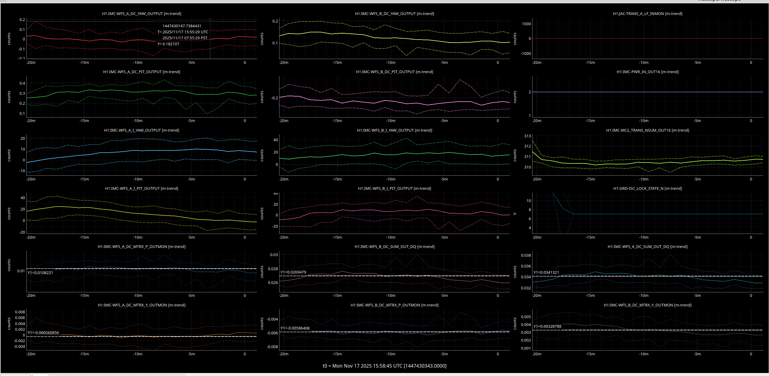
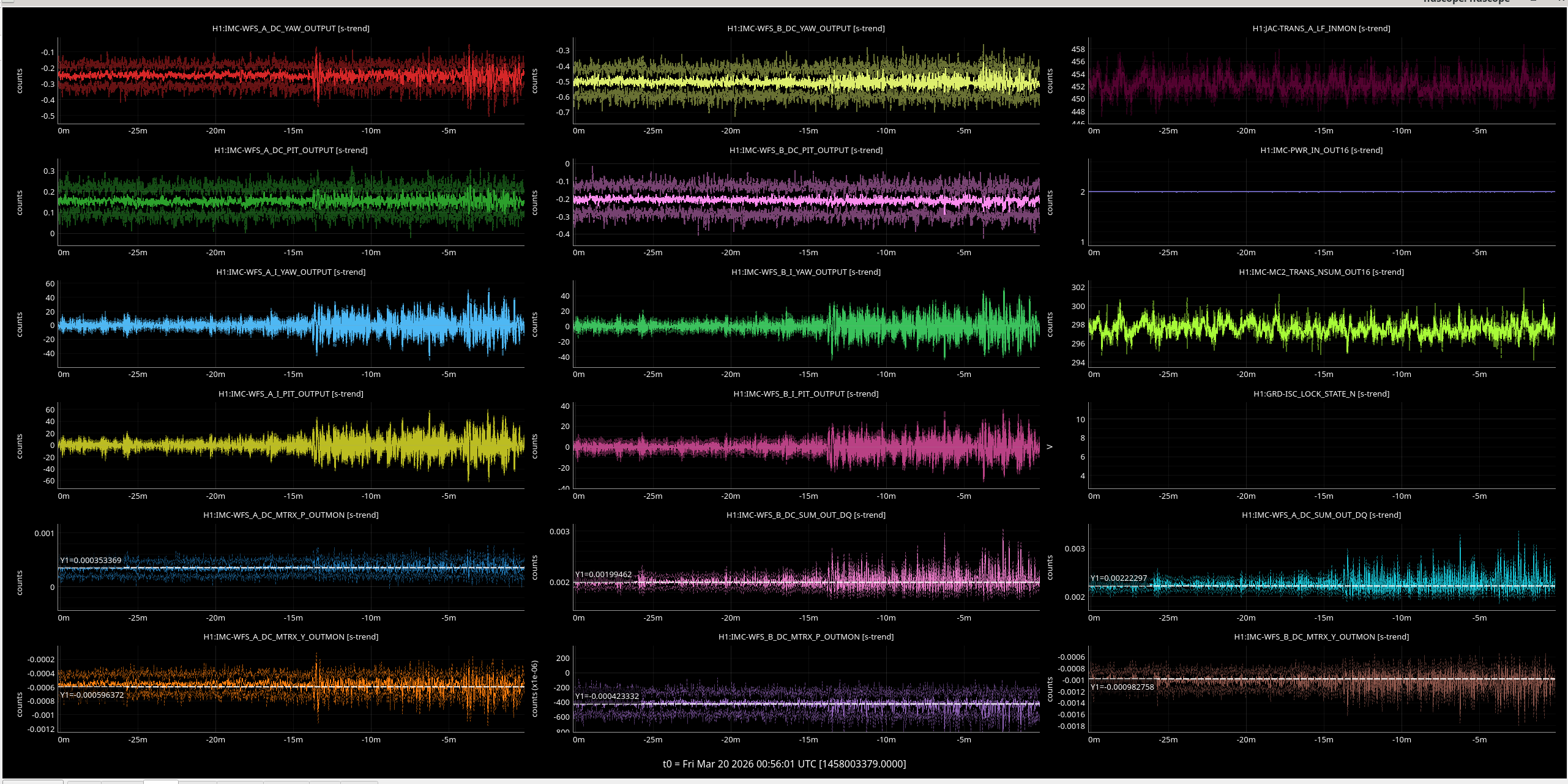
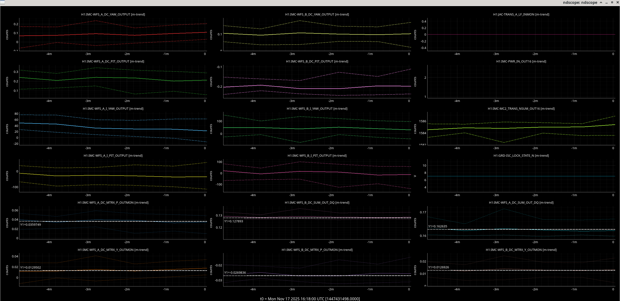
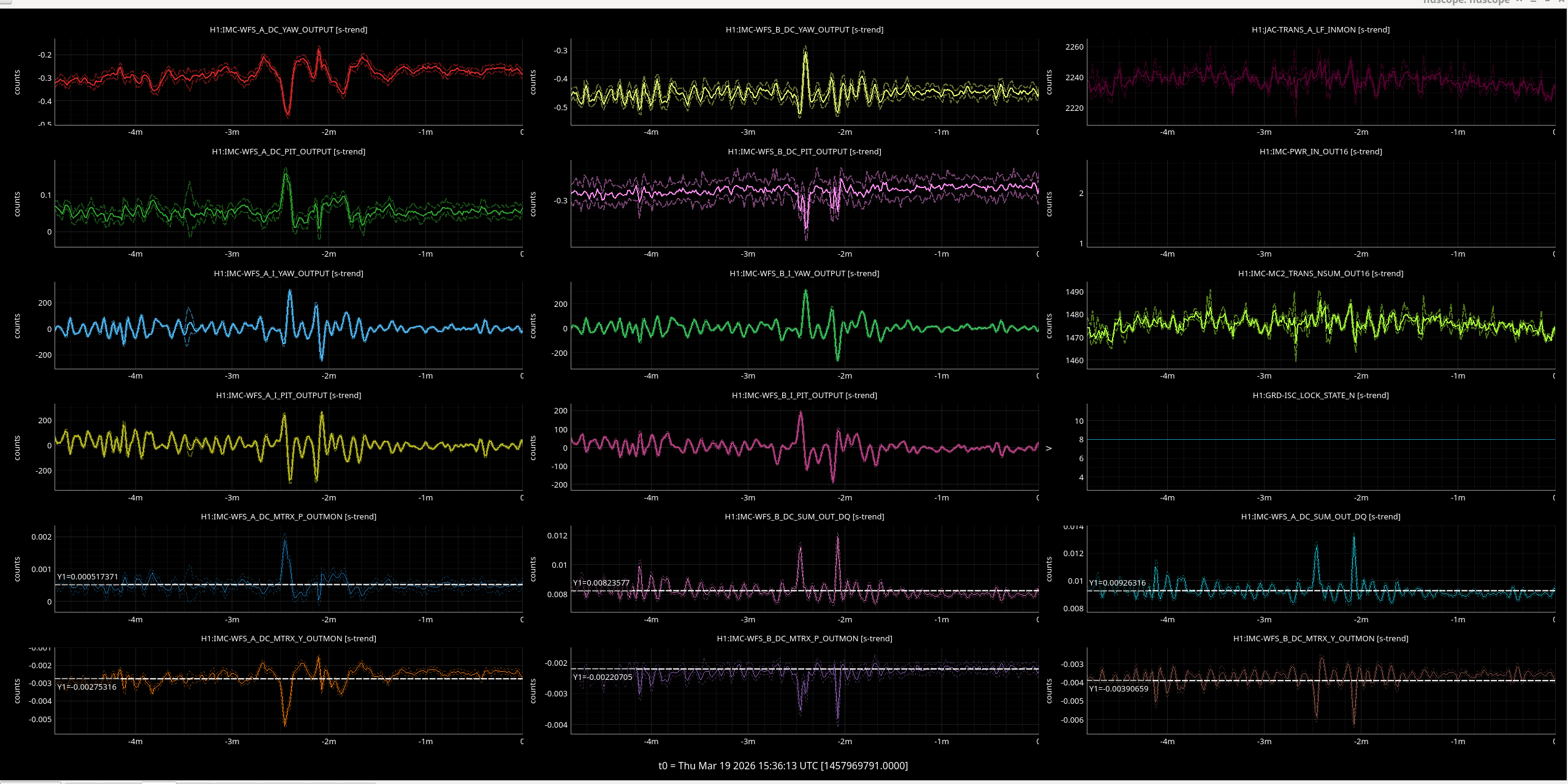
Summary: Since I had trouble seeing a noticeable improvement in jitter by looking at the IMC WFS in this alog #89988 where the PSL output power was 2W, I looked at times when we were at 10W PSL output power to see if we were limited by shot noise. The measurements at 10W show that we might have decreased jitter but I checked the QPD sum values for the measurements after JAC was installed vs. before and we are near the edge of the QPDs.
I took reference times, when our input power was 10W to see if this gave a better measurement of jitter
Time 1: 2025/11/17 16:13:17 UTC during initial alignment. Without JAC.
Time 2:2026/03/19 15:31:23 UTC during commissioning when HAM1 was at vacuum.
Image one shows the yaw measurement, there is again a difference in the value at DC of the QPD ASDs. It looks like the peaks seen between 40 and 1000 Hz are slightly better with JAC than without JAC but it is only obvious on WFS A and B QPDs (top left plot comparing green and purple lines for WFS A and red and yellow lines for WFS B).
Image two shows the pitch measurement, there is again a difference in the value at DC of the QPD ASDs. It looks like the peaks between 40 and 1000 Hz are slightly better with JAC than without JAC but it is only obvious on WFS A QPD (top left plot comparing green and purple lines).
I also checked that the QPD sum values changed between my reference times during O4 and after JAC installation. See these four images.
1. 2W reference time during run. A and B QPD SUMs were arpund 0.03 counts.
2. 2W reference time after JAC installation. A and B QPD SUMs were arpund 0.002 counts. Maybe we are now nearer the edge of the diode?
3. 10W reference time during run. A and B QPD SUMs were around 0.16 and 0.13 respectively.
4. 10W reference time after JAC installation. A and B QPD SUMs were around 0.009 and 0.008 respectively. Maybe we are now nearer the edge of the diode?


Jennie W, Sheila D, Jenne D
Summary: JAC TRANS A LF calibration gives correct ratio now but PD is too noisy to give us sensible values when the light pipe is closed.
On Tuesday I changed the scaling filter in JAC-TRANS_A_LF to give us an output calibrated in W out of HAM1. The previous calculation (alog #89805) gave us too large a value.
When we checked the power on the JAC-TRANS PD in chamber (alog #89251) we did not monitor the JAC input power between successive measurements and since we had purge air on I think the input power drifted.
To avoid confusion I just took a time when the output power was measured in chamber and used the JAC TRANS LF OUTPUT power at that time to give the calibration into HAM2 W.
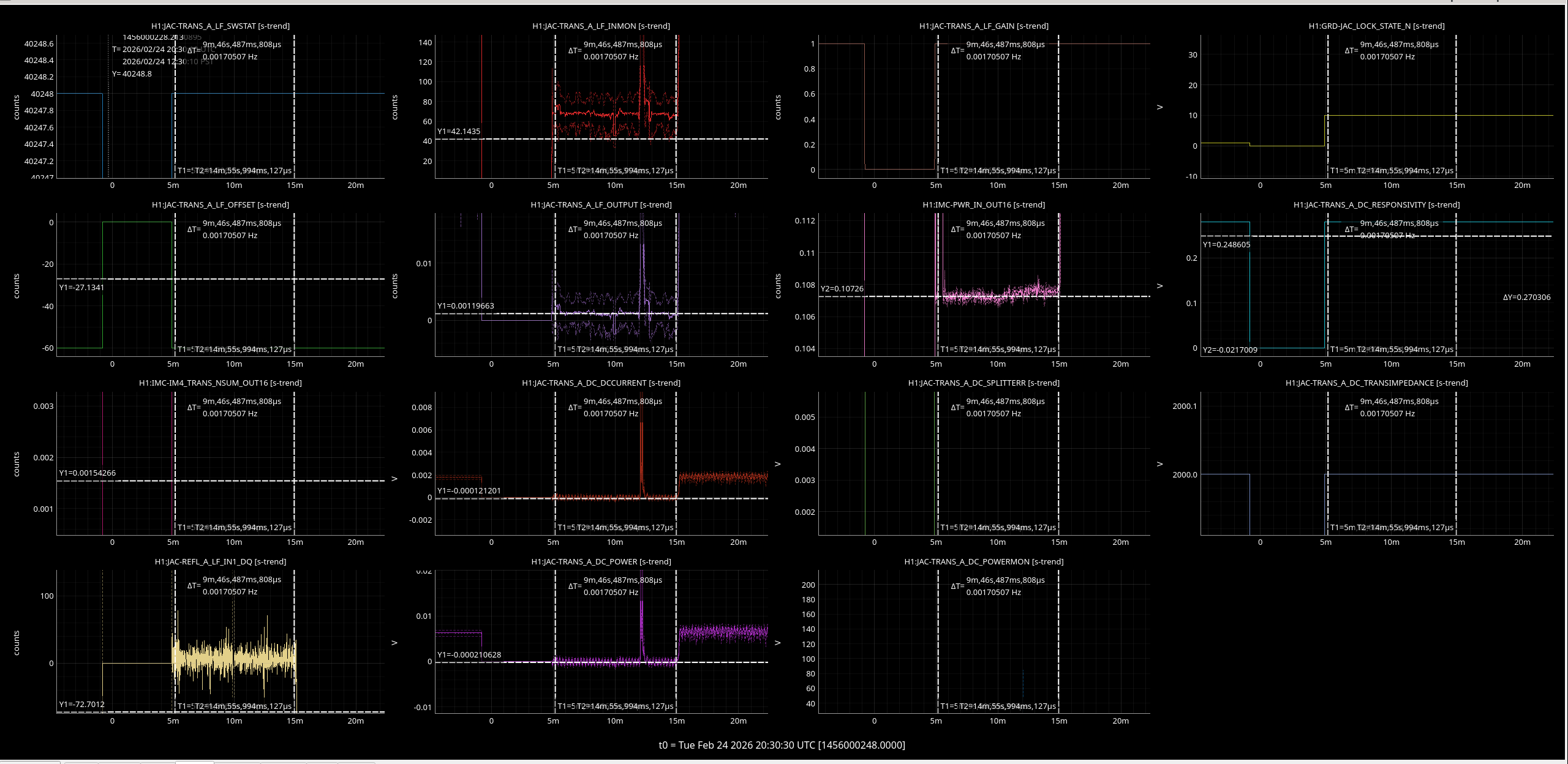
When we measured 96mW out of HAM1, the JAC-TRANS_A_LF filter bank was roughly calibrated into mW (using standard values for V/count, A/V, mW/A) but had not been calibrated using in-chamber measurements.
For 96mW we got 0.00120mW on JAC_TRANS_A_LF_OUTPUT on 2026/02/24 at 20:30:10 UTC, see image.
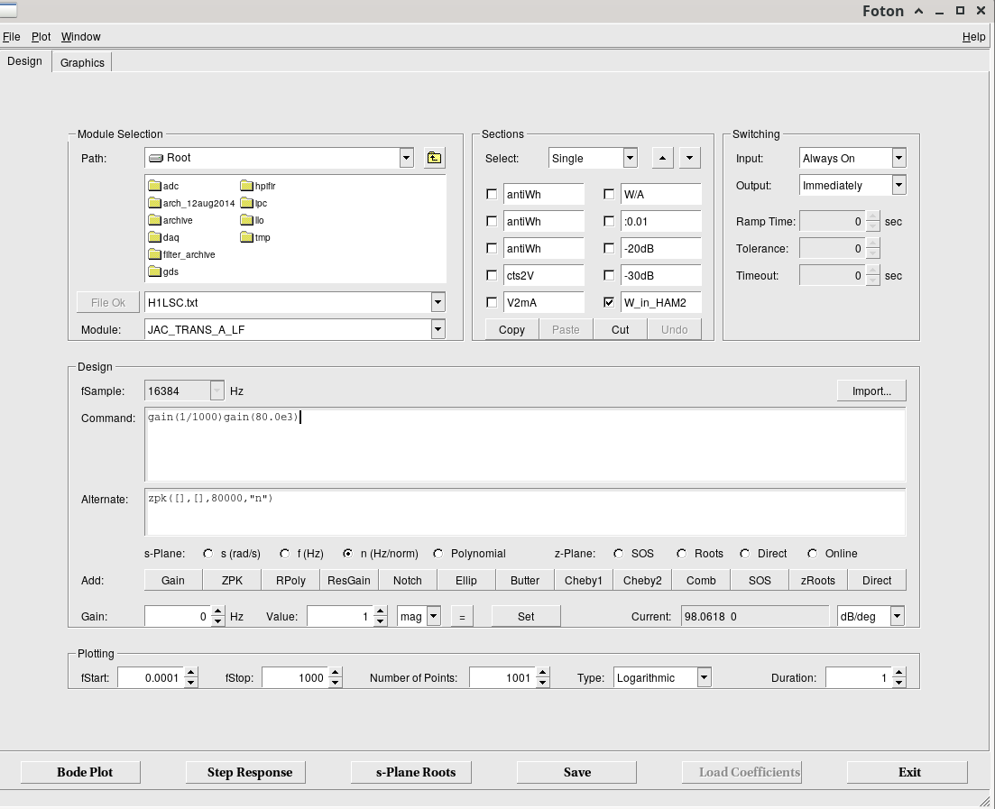
We want the output in W so the calibration factor is 80000/1000. This value is now in FM10 in the filter bank. Unfortunately the signal still is too nosiy to give a sensible looking value and so changes from -20 to 20 W.
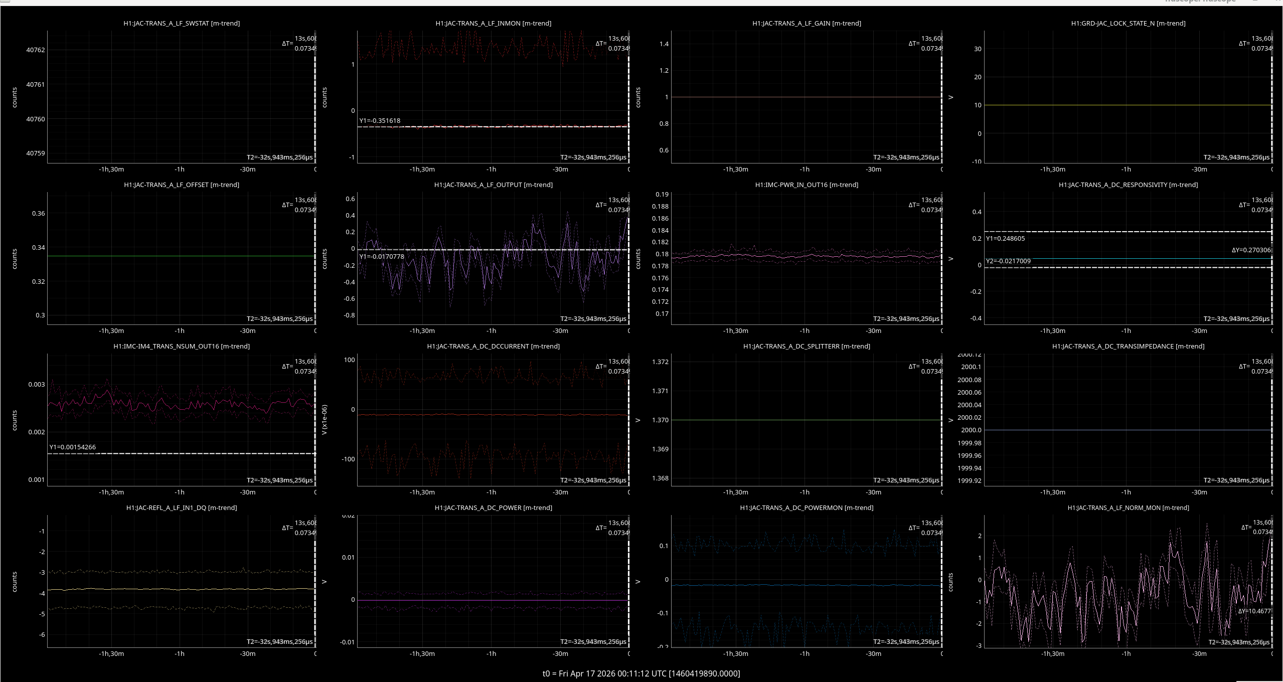
Jenne and I put a 0.01Hz pole to low pass the noise in the FM7 filter, and also tuned the offset on the filter bank.
This channel still seems too noisy though (image) and changes between -0.5 W and 0.5.
So maybe we need a filter that goes down to lower frequency, or its just too noisy a PD to use as a JAC input power monitor.
I'm going to revisit this after the BSC2 work when we next have an opportunity to open the light pipe.
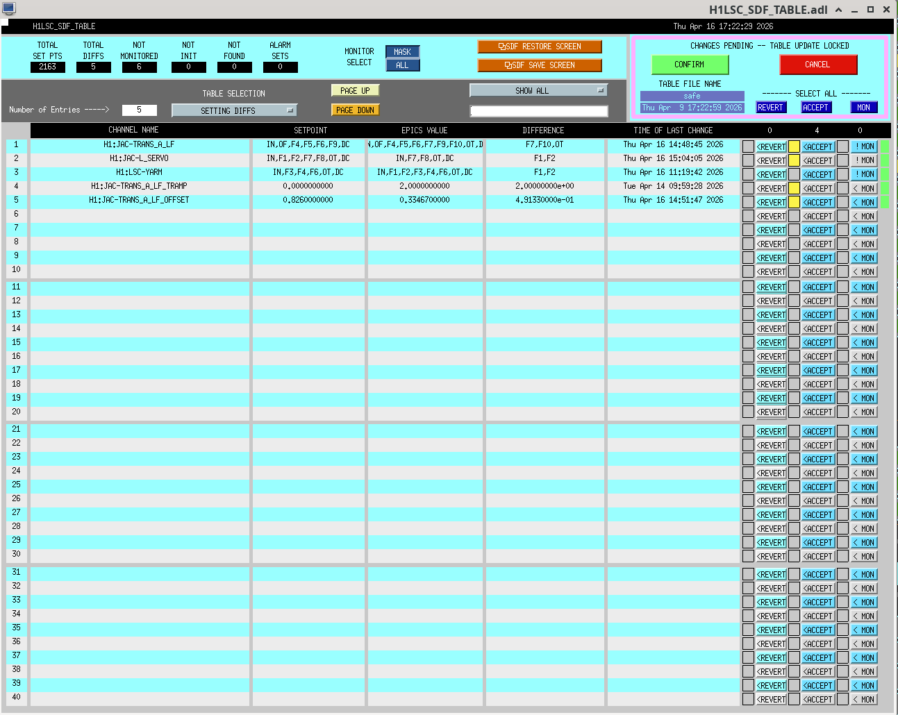
I accepted the sdf diffs for JAC-TRANS_A_LF - filters, offset and tramp.
I also turned off the FM1 and FM2 filters in JAC-L_SERVO as Jenne noticed the integrator hwas causing a large value at the output of the servo. Checking the 'DOWN' state in the JAC guardian these should not be on so I accepted them as off in sdf.
Today i noticed the output of the JAC SERVO wa son so i turned it off and sdfed it. This should also be the case when in DOWN.

Sheila, Keita, Jennie W, Jenne D, Georgia B.
We want to be able to power up to 20W in JAC to check the POP beam.
We were loosing lock with about 8W into JAC because the REFL shutter was closing. Jennie Wright measured 6mW on the REFL diode with 2W input to HAM1 and JAC unlocked yesterday. This corresponds to 0.58V on the shutter trigger diode. The threshold cannot be set above 2V, which means we would unlock when 21mW hit the diode. Jennie Wright added a ND05A into the path before the refl diode, and another ND05A in front of the shutter diode.
Now, with 2W input to HAM1 and JAC unlocked, we should have 2mW on the REFL diode, and the shutter diode votlage is 0.18V. The threshold of 2V now will shut the shutter with 22mW on it.
Gaurdian changes:
The JAC error signals are normalized by the PSL input power if we use the laser power guardian to change the input power, so we shouldn't need a power scaling like 89708. People have been using the rotation stage instead of the guardian to adjust the power because the laser power guardian would go into fault if the power was below 1W (people have been going below 1W while HAM1 is vented.) Jenne Driggers adjusted the fault in LASER_POWER and added a 200mW state to the laser power guardian, so now we should use this guardian whenever we want to change powers, even below 1W.
We also hard coded the gain used for locking JAC in the down state, although this could be reverted to allow the power normalization to work again, once that has been updated to take into account the new ND filters. Once this was done, we could lock JAC at a variety of powers and also change the requested power after it was locked.
Georgia B and I also had a look at the IMC guardian, which has not generally been able to lock the IMC except at 2W. There was some code in the down state of IMC LOCK that was supposed to adjsut settings for lcokign at different power levels, these were unused except for the IN1 gain setting used for acquisition. Georgia and I adjusted some of these numbers and watched if the IMC would lock, we didn't take much time to test it but we did once twice see the IMC lock with 10W + input power, so that is promising.
At Elennas' good suggestion, I added the IMC_power_adjust_func() to the IMC_LOCK's ACQUIRE state, so that it will adjust the IMC's FASTGAIN, so that the fast gain won't be wildly high when trying to acquire at higher powers.
I did modify the function, so that if we're in ACQUIRE, it uses a FASTGAIN 5dB lower than the operating nominal gain. This makes it match the 2W acquisition situation, where the fastgain was always acquiring at 0dB, and then for a 2W IMC lock would increase during the BOOST state to 5 dB.
The IMC will lock at 10W, but it takes a long time. It's a little happier at 8W. It's still perfectly happy at 2W (which makes sense, since none of the 2W settings have changed).
I'm pausing any further testing, since the Xarm is open for our green peek.
Locked with 2W input, JAC REFL A LF signal was constantly railing regardless of the purge air level. Turns out that we were using two stages of 1:10 whitening.
I went to the floor and turned one stage off on the front panel of the RFPD DC interface D1102079 (circuit diagram D1102060) in ISC R1 rack and disabled the corresponding dewhitening filter. I could have disabled both, but with an ND0.5 filter JennieW was installing, this will do the job for now.
I always forget this but gray switch up=1 stage active, middle=2stages, down=0. I put two labels on the front panel so I don't have to remember.


I've found that the pico mount for 50:50 BS on the REFL WFS sled in front of ASC REFL_A was loose and rotated counter-clockwise seen from the top by a huge amount (1st attachment, orange arrows show the direction of rotation). Our guess is that the BS mount was bumped when we were leaning into HAM1 from -Y door to work on the JAC output periscope. In general, it's hard to rotate the mount clockwise seen from the top even if the screw is not super tight (because the screw tends to be tightened), but it's easier to go counter-clockwise.
When this was found, the beam was hitting the +X-Y edge of the mirror, there was no clear reflection beam found so no beam on WFSA, but somehow the ugly transmission beam with lots of diffraction patterns was making it to WFSB.
We reverted the RM1 and RM2 bias sliders back to O4 level (RM1 PIT=-180, YAW=-57, RM2 PIT=890, YAW=-530) and I confirmed that the centering on the 2" lens was good. WFSA mount was screwed down tight to the post.
RM1 bias was adjusted further (RM1 PIT=-190, YAW=263) to roughly center the beam on WFSB.
At this point I looked at the beam on WFSA and it was still off mostly in YAW but there was also a large PIT offset. These were taken care of by adjusting the picos I've just screwed down.
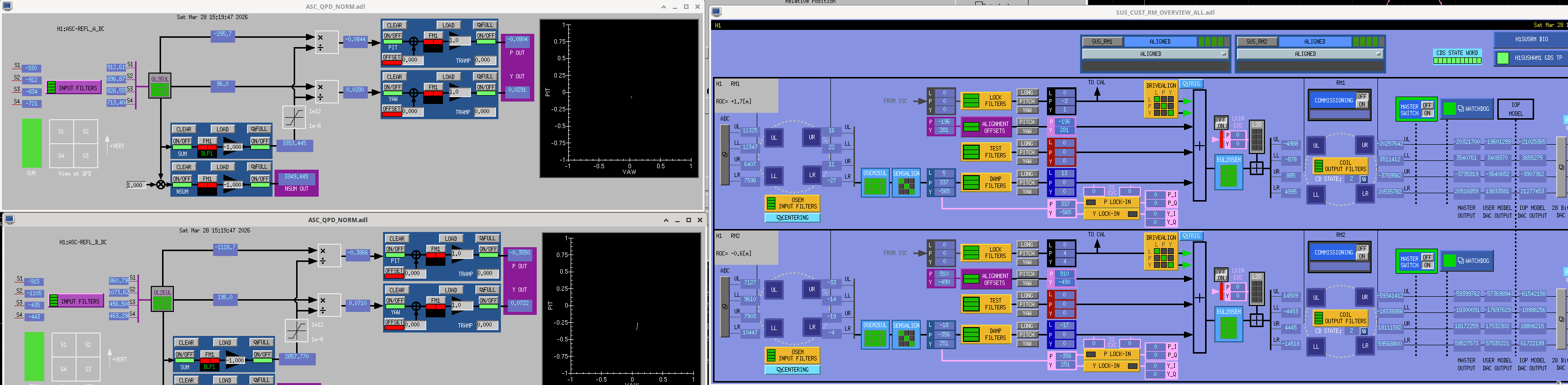
I enabled the REFL WFS centering which worked right away. LSC REFL diodes are receiving almost equal amount of light. We'll have to make sure that the beam is not clipped on LSC diodes. Anyway, I relieved the ASC using RM sliders and ended up these numbers: RM1 PIT=-192, YAW=274, RM2 PIT=910, YAW=-532.


Making sure that the beam is centered-ish on the LSC sensors
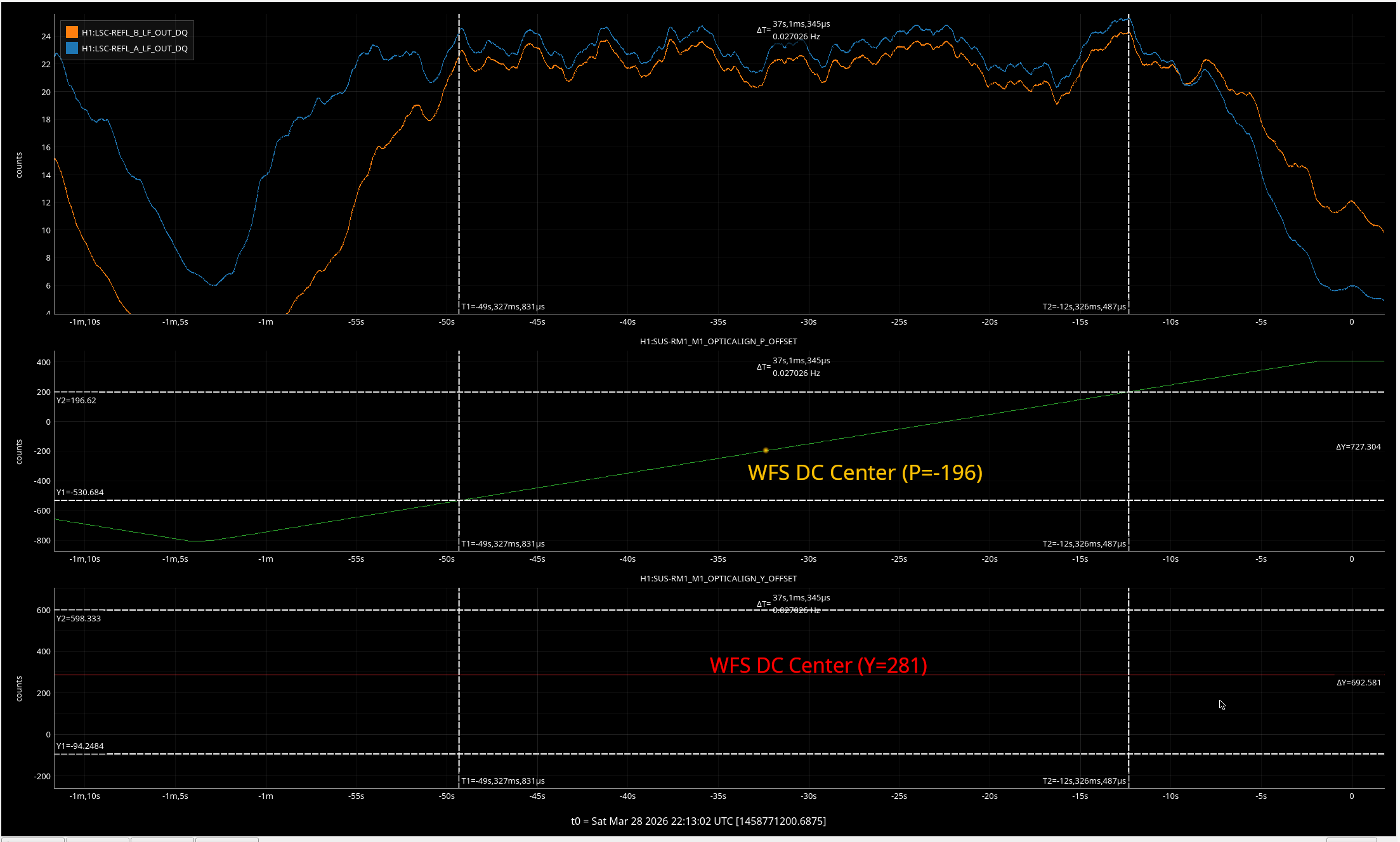
We enabled the WFS DC centering, relieved the WFS output by RM sliders, disabled the WFS centering. Then scanned RM1 in PIT to find out where the LSC REFL A and B DC starts to fall off, and make an average position in terms of RM1 PIT offset ("plateau center"). In general the plateau center is not the same as WFS DC center.
Use the common pico for the REFL LSC sensors to make the plateau center come closer to the WFS DC center. See the 1st attachment.
Repeat the same thing for YAW. We noticed that LSC REFL B is not exactly the mirror image of REFL A, mostly horizontally, as you can see from the 2nd attachment. If they are, we expect both to start falling at the same time but they don't. To fix that we need to touch up the non-pico 50:50 splitter that steer half of the beam to REFL B, but we chose not to do it because the scan range you see here is huge, and beam will totally fall off of WFSB before LSC REFL A and B starts falling.
After all of these and minor tweaks here and there, we ended up with: RM1 P = -196, Y=281, RM2 P=910, Y=-490.
Tilting WFSA in YAW
I checked the beam position along the REFL path and unfortunately the reflection from WFSA was hitting the mirror mount. I tilted the WFS clockwise, paying attention NOT to change the optical path length significantly. After this, Jason and Jennie used pico to steer the beam back to the center of WFS. I confirmed that the WFSA reflection goes into the beam dump.
Final check
I rechecked the beam position along the REFL path. Nothing was grossly off-centered except for 1" mirrors and BS on the WFS sled (this was always the case).
On M2, RM1 and M5, the beam position looked OK though it was hard to say anything quantitatively. No picture for these.
1" lens for the LSC censors, 2" lens on the WFS sled as well as 1" lens on the WFS sled looked good.
Reflection of all LSC and ASC REFL sensors fall on the beam dumps.
Pictures will follow.
I looked at the POP path too but it wasn't flashing and it was already 4PM so we gave up. We'll continue on Monday.


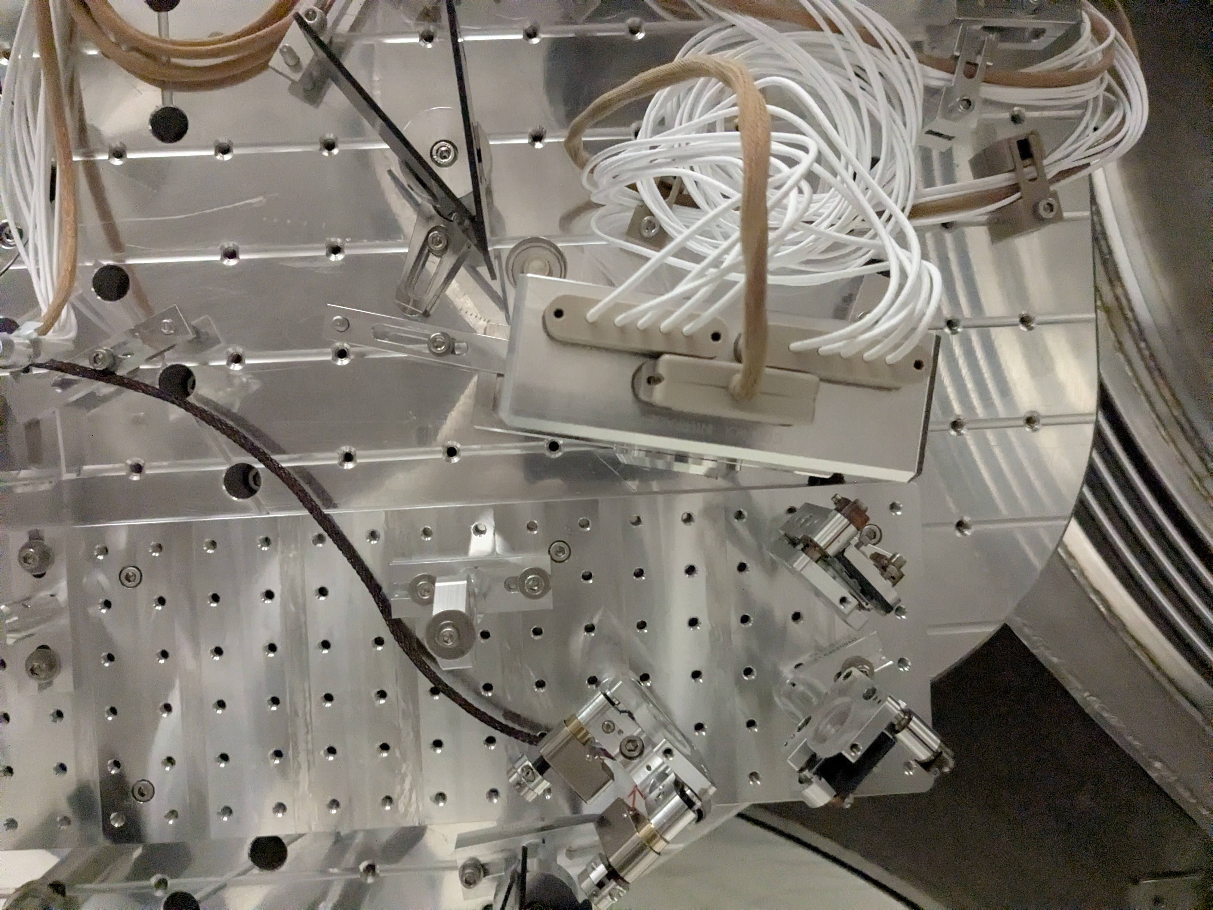
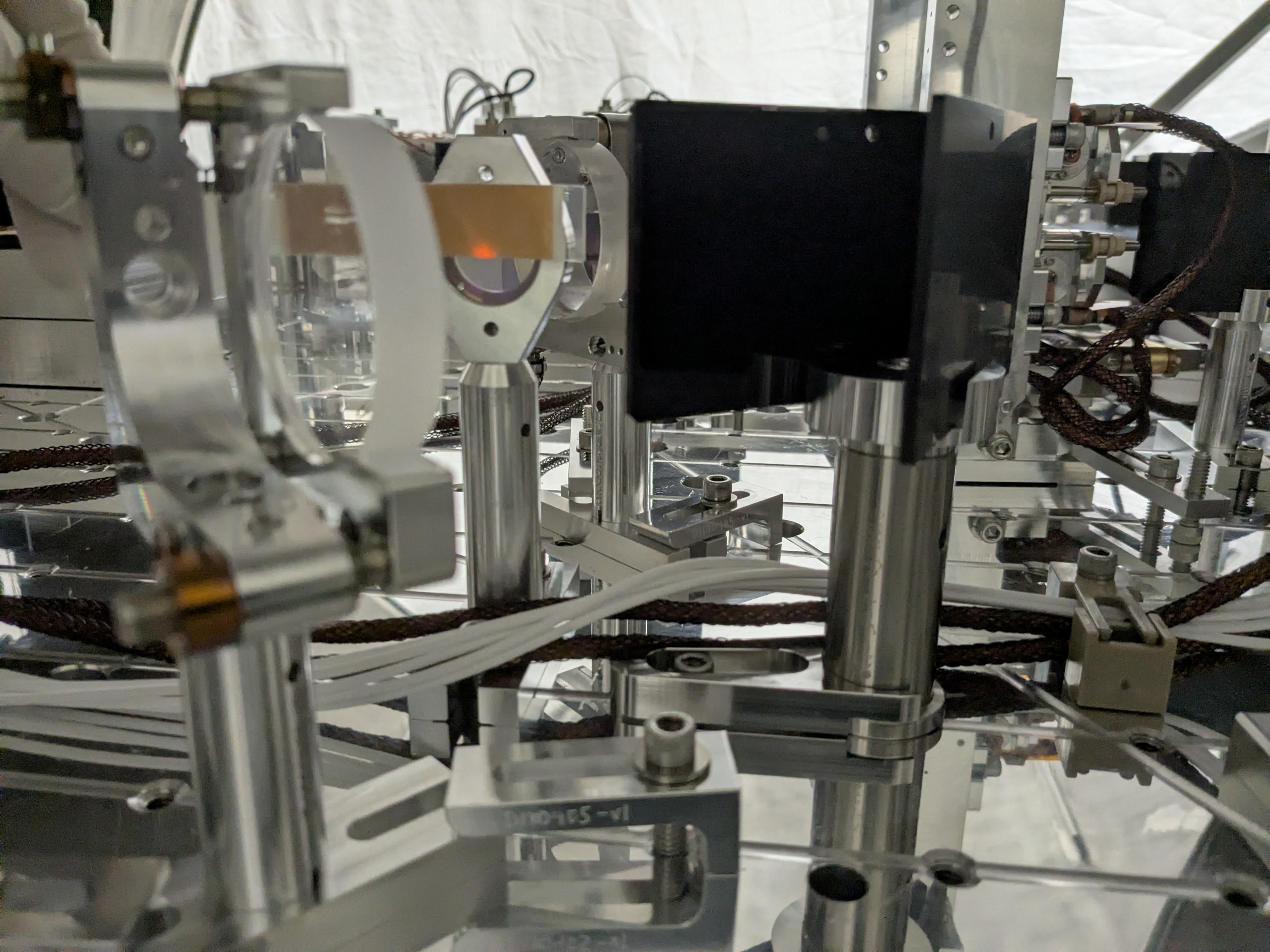

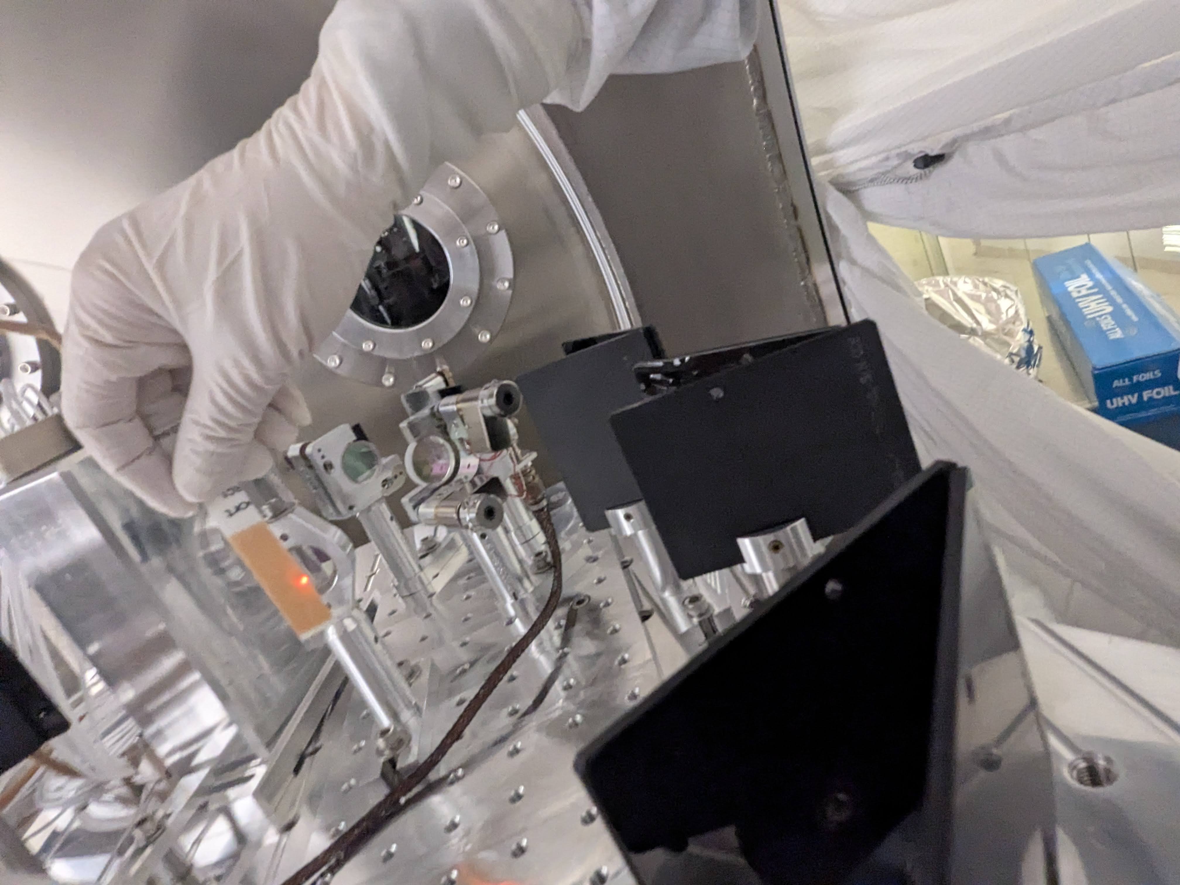


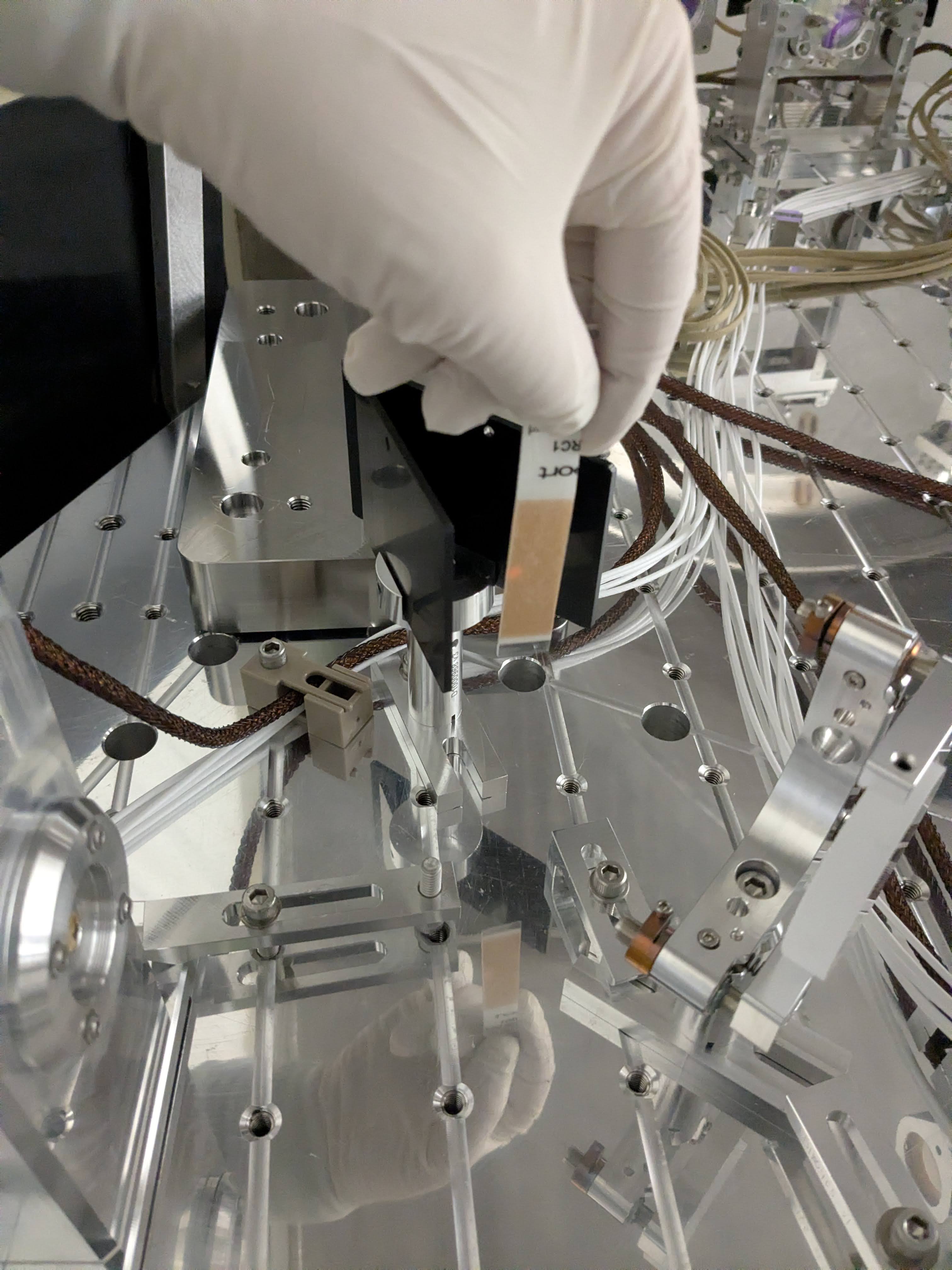
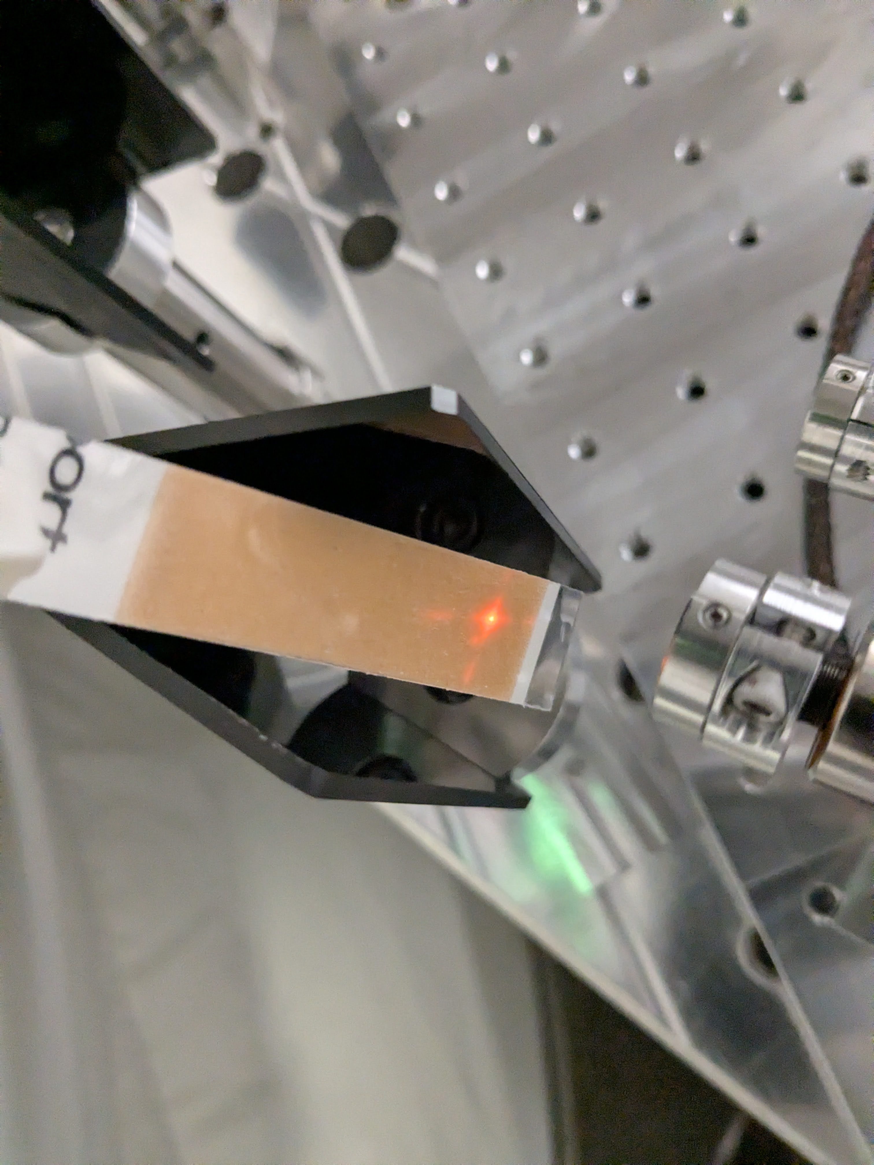


Correction: In the above alog text, "LSC_REFL_B_ghost.jpg" points to the picture for REFL_A ghost beam. This is the correct one: LSC_REFL_B_ghost.jpg.
The JAC heater turned on at 8:00 PM PT. JAC-HEATER_POWER_SET is set to 3.
TITLE: 03/13 Day Shift: 1430-2330 UTC (0730-1630 PST), all times posted in UTC
STATE of H1: Planned Engineering
INCOMING OPERATOR: Ryan C
SHIFT SUMMARY:
The Commissioning crew today were focused on trying to get PRMI locked and stable for most of the day. Thye touched up the REFL A alignment which helped.
But there seems to be some power lost somewhere.
This spreadsheet was created to document the difference in the ratio of IMC Trans power/IMC input power back in the O4 run and now. Specifically when the PSL is set to 2 Watts. Feel free to update this in the future.
The Gain for H1:ALS-C_TRX_A_LF_GAIN has been bumped from 1.5 to 3 to get past FIND IR without issue.
This may not be the only gain that has been turnt to 11 to get DRMI to almost lock today, Sheila will be posting an alog later with some laser power acounting that may shed more light on that situation. Yes the Pun was intended.
LOG:
| Start Time | System | Name | Location | Lazer_Haz | Task | Time End |
|---|---|---|---|---|---|---|
| 14:39 | FAC | Randy | Xarm | N | Plowing the Tumbleweeds | 17:02 |
| 15:06 | H2O | Water contrators | Well | N | Testing the well water | 18:06 |
| 17:04 | VAC | Travis | Cleaning Racks & west bay, All ES and Mids | N | Looking for parts | 19:34 |
| 17:26 | FAC | Randy | LVEA | N | Walk about in the LVEA | 17:49 |
| 18:28 | PEM | Ryan | CER | N | Checking Dust mons | 18:31 |
| 18:32 | SPI | Jeff & Josh | Optics Lab | Yes | Working on SPI setup. | 23:07 |
| 18:43 | ISC | Sheila & Oli | LVEA | Yes | Tweaking alignments on ISCT1 | 19:09 |
| 18:50 | OPS | LVEA IS Birfurcated HAZARD | HAM1 | LOCAL | LVEA Bifurcated LASER HAZARD | 11:29 |
| 19:37 | EE | Marc | LVEA & CER | N | placing stickers and parts. | 20:07 |
| 20:36 | EE | Fil & Marc | Mid Y | N | getting cables. | 21:14 |
| 20:49 | VAC | Gerardo | EndY | N | Anulus ion pump controller testing, unplug replug | 21:24 |
| 21:15 | PEM | Ryan C | LVEA | N | chasing cables | 22:25 |
| 23:24 | Cheta | Sophie | Cheta Lab | local | Workign on Cheta | 00:24 |
Jennie W, Jenne D
We need to check the positions of IM1 and 2 as we have now closed all 3 loops for the IMC alignment.
Jenne was windering how our input alignment to the IFI compares to before the vent.
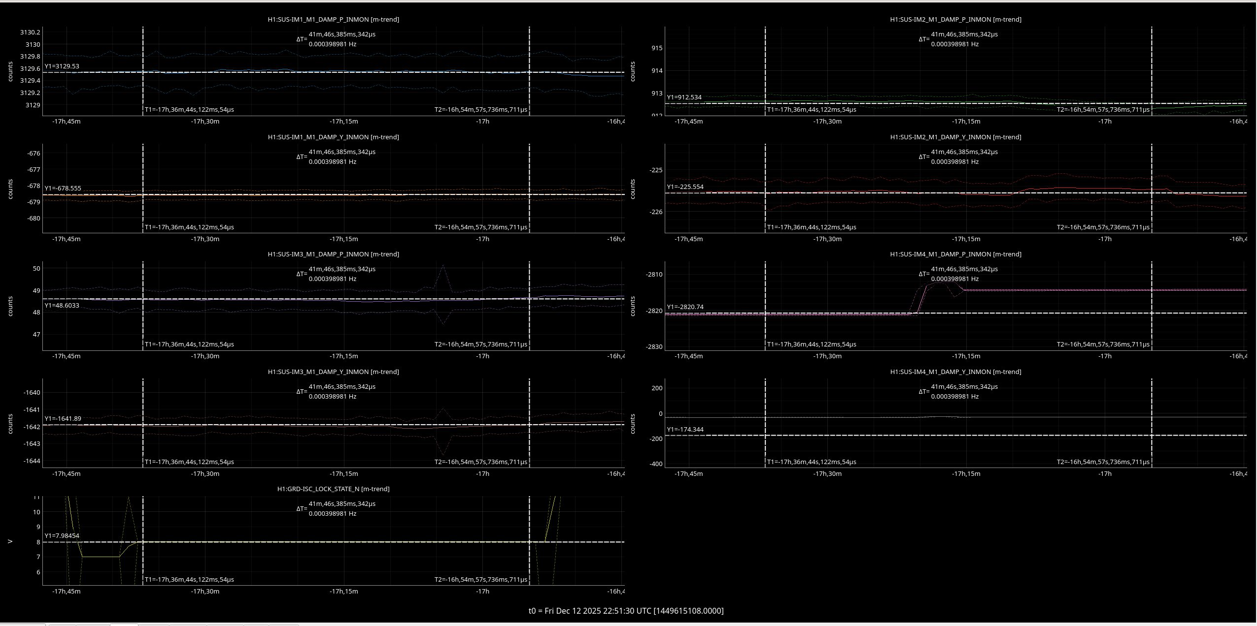
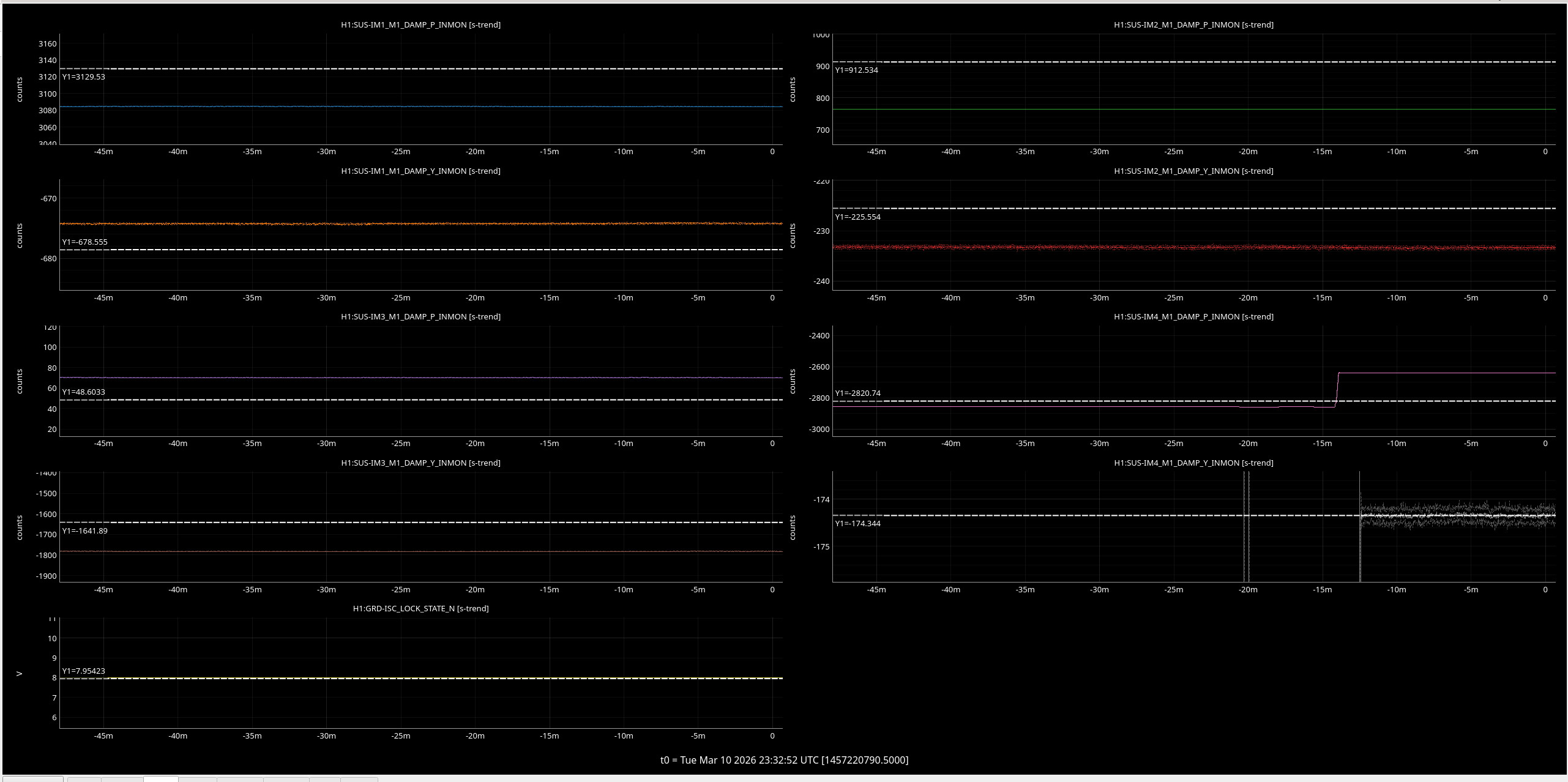
We compared the IM 1 and 2 pitch and yaw positions in manual initial alignment between today and the 12th of December - when we were doing our last locking before the vent.
This comparison is during manual initial alignment which is state 8 in the ISC_LOCK guardian.
The first pic is the 12th December, reference time is 05:21:30 UTC.
The second pic shows today with y cursors at the reference values. The biggest difference is IM2 pitch which is ~120 counts lowewr than it was, the other 2 DOFs are tens of counts off.
I also included IM3 and 4 in my plots but I think we have intentionally changed IM3 since the vent to improve alignment onto IM4 trans and IM4 is controlled.
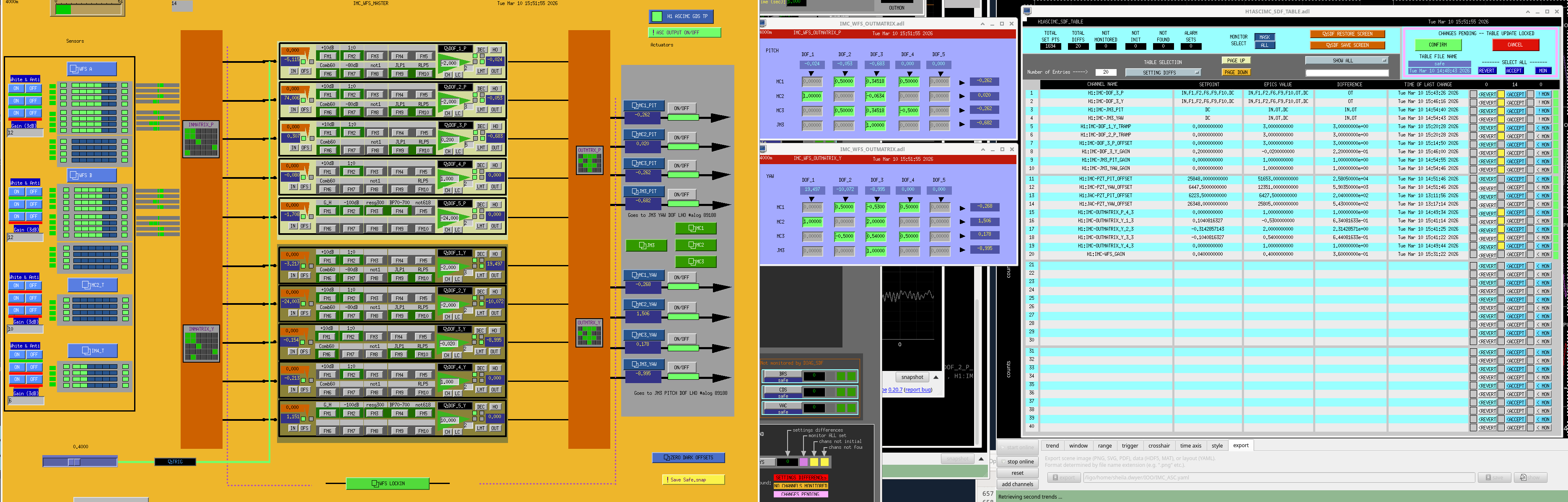
Jenne Driggers, Jennie Wright, Sheila, Ryan Short, Ryan Crouch, Tony
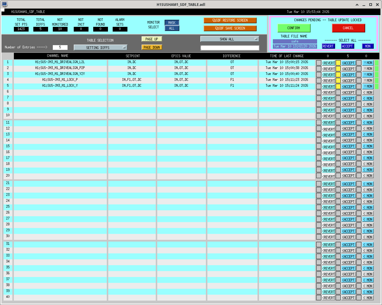
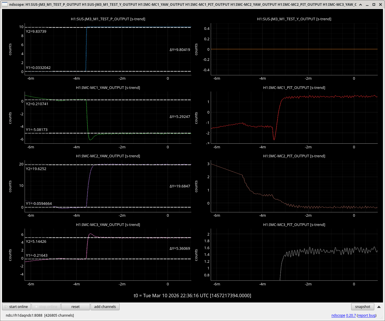
We are running all three IMC ASC DOFs. Jenne turned on DOF3 pitch without issue once she set up the feedback through JM3. The YAW DOF was unstable, we checked the output matrix for yaw. With the gain increased on DOF1+DOF2 we put 10 couns on JM3 pitch test, and measured the responses on MC1, MC2, MC3 outputs from the IMC ASC. (screenshot attached). We scaled these responses to give us the new output matrix, this worked well once we flipped the sign. We accepted these changes in SDF so they should be used everytime the IMC locks from now on.
In the process we remembered that IMC ASC has the intergrators in the asc model, not the suspensions.
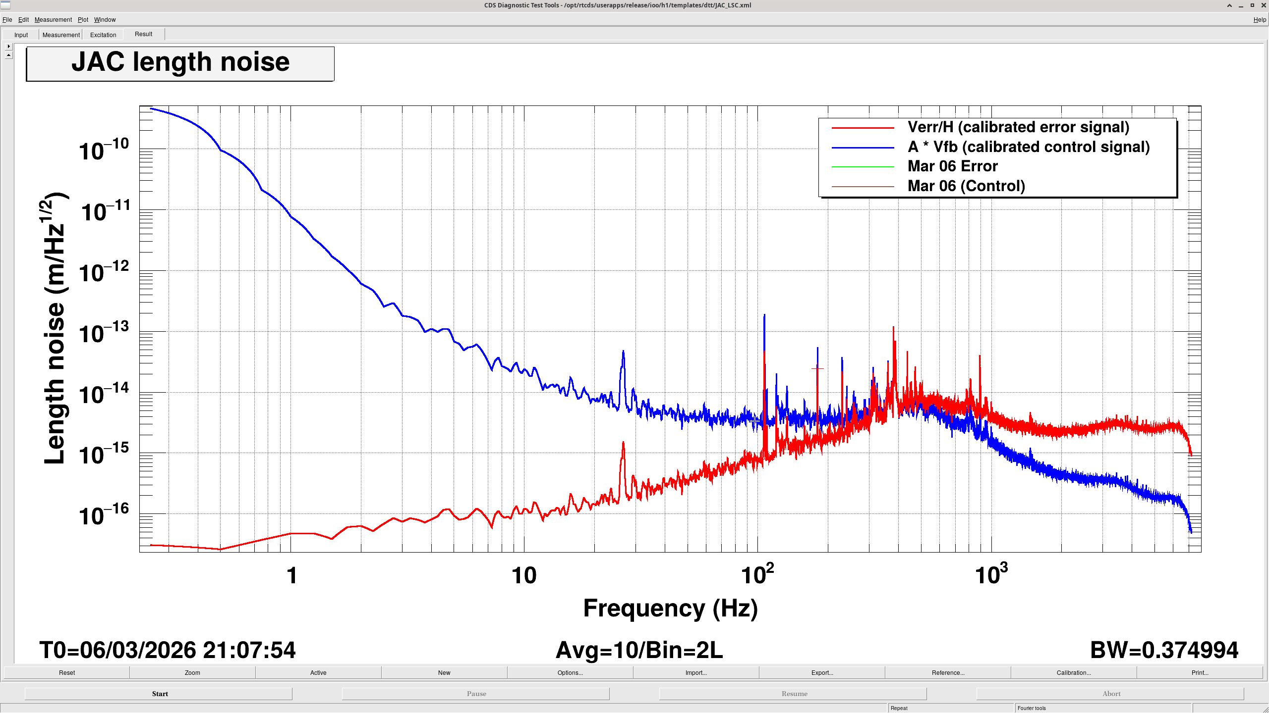
The calibrated error signal and feedback signal spectra were measured to estimate the free-running length motion of the JAC. Below the unity gain frequency (UGF = 400 Hz), the feedback signal represents the cavity length motion, while above the UGF the error signal represents the motion. The estimated length noise is well below the design assumption and does not appear to limit the JAC performance.
The spectra of the calibrated error signal and feedback signal were measured to estimate the free-running length motion of the JAC.
- Below the UGF (400 Hz), the feedback signal represents the cavity length motion.
- Above the UGF, the error signal represents the cavity length motion.
Around 400 Hz, the spectrum appears slightly inflated because of the phase bubble, but the actual noise level is expected to be approximately flat in that region.
- Above 30 Hz
Above 30 Hz, the spectrum becomes flat. This is likely not real cavity motion, but instead electronics noise from the readout chain. A more careful calculation is needed to identify the exact source, but it is most likely the photodiode or the ADC.
Since the incident power is currently 1 W, this noise floor is expected to decrease if the input power is increased.
- Below 10 Hz
Toward DC, the spectrum rises approximately with an f-3 slope. This is interpreted as drift in the PZT control signal caused by temperature drift.
Therefore, the actual cavity length variation at low frequencies is expected to be smaller than what appears directly in the measured spectrum.
- Estimated Length Noise
Looking at the spectrum around 10 Hz, where the above effects are not expected to dominate, the cavity length noise is estimated to be approximately 2 × 10-14 m/rtHz.
In the design, the cavity length motion was conservatively assumed to be 1 × 10-12 m/rtHz at 10 Hz.
Therefore, the measured result is well below the design assumption, indicating that the loop design and the JAC do not introduce problematic intensity noise or phase noise.
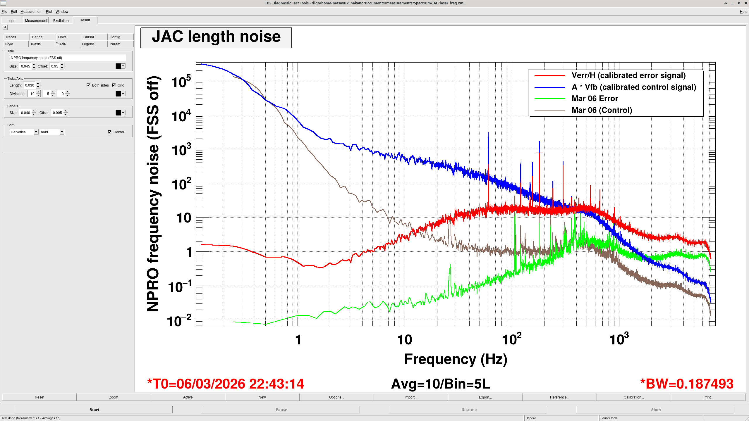
As a sanity check, the same measurement was repeated with the FSS unlocked. In this measurement, the vertical axis was converted into laser frequency noise by multiplying the calibrated length signal by
FSR / (lambda / 2)
where the free spectral range is given by
FSR = c / L
with c the speed of light and L the cavity round-trip length. For the JAC, L = 2.02 m.
The resulting spectrum, shown in the second plot, is approximately 100 Hz/rtHz at 100 Hz. This is consistent with the typical frequency noise of the NPRO laser.
This also confirms that the JAC is sufficiently quiet compared with the NPRO noise level.
Summary
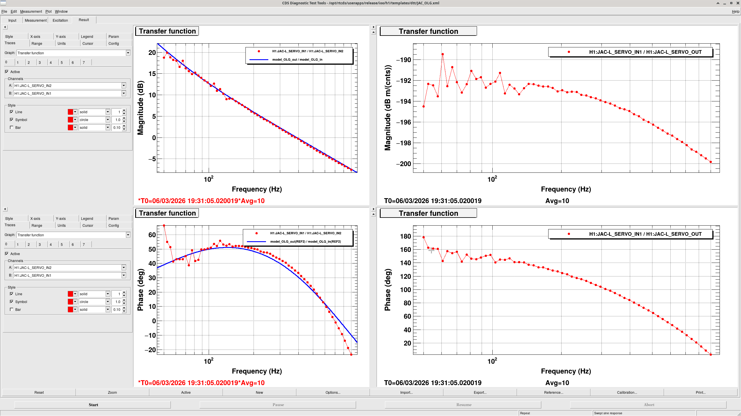
The JAC length servo was designed to set the unity gain frequency (UGF) at 400 Hz. Additional low-frequency boost was implemented to improve suppression below 50 Hz. The open loop gain (OLG) was measured and compared with the servo model.
Details
PZT actuator compensation
The PZT driver has poles at 1 Hz and 400 Hz, and a zero at 10 Hz.
To compensate for this response, a zpk(400, 10, 40) filter was implemented in the servo.
With this compensation, the actuator response becomes approximately a first-order low-pass with a cutoff frequency of 1 Hz.
Unity gain frequency
The servo gain was then set so that the unity gain frequency (UGF) is 400 Hz.
The phase margin at 400 Hz is 37 degrees, which includes the phase contribution from the first-order low-pass (90 degrees) and the additional phase delay in the system.
Low-frequency boost
A 1–50 Hz boost filter (first-order pole-zero boost filter) was implemented to improve low-frequency suppression.
The phase contribution of this filter is –7 degrees at 400 Hz, resulting in a total phase margin of about 30 degrees at the UGF.
Also, the integrater was implemented below 1Hz. Combination between boost and integrator gives f^{-2} slope below 50Hz.
Open Loop Gain measurement
The open loop gain (OLG) has been measured. A comparison between the measured OLG and the model is shown in the attached plot in the left panel. The right panel is the TF of the PZT.
MEDM interface
The OLG measurement template can be opened from the spectrum/OLG button in the bottom-right corner of the MEDM screen.
Summary
The calibration of the PDH error signal and the feedback path was derived using the Guardian-based signal normalization. The normalized PDH error signal allows the optical gain to be calculated analytically. The transfer function from L_SERVO_OUT to the cavity length actuation was measured and modeled, separating the optical gain and the PZT actuator response.
Details
Normalized PDH error signal
With the Guardian normalization, the PDH error signal at L_SERVO_IN1 can be written as
V = x / (1 + x^2)
where V is the signal at L_SERVO_IN1, and
x = l / HWHM
where l is the cavity length fluctuations and HWHM is the cavity half-width at half-maximum.
Using the finesse F, the cavity HWHM is
HWHM = lambda / (4F)
At the lock point (x = 0), the slope of the error signal is
dV/dx = 1
Optical gain
Therefore, the optical gain is
dV/dl = dV / d(x * HWHM) = 4F / lambda
Using F = 125, lambda = 1064e-9 m, the optical gain becomes
dV/dl = 4.70e8 cnts/m
Error signal calibration
To convert the signal at L_SERVO_IN1 to cavity length, we apply the inverse of the optical gain.
Calibration factor = 2.128e-9 m/cnts
Plant measurement
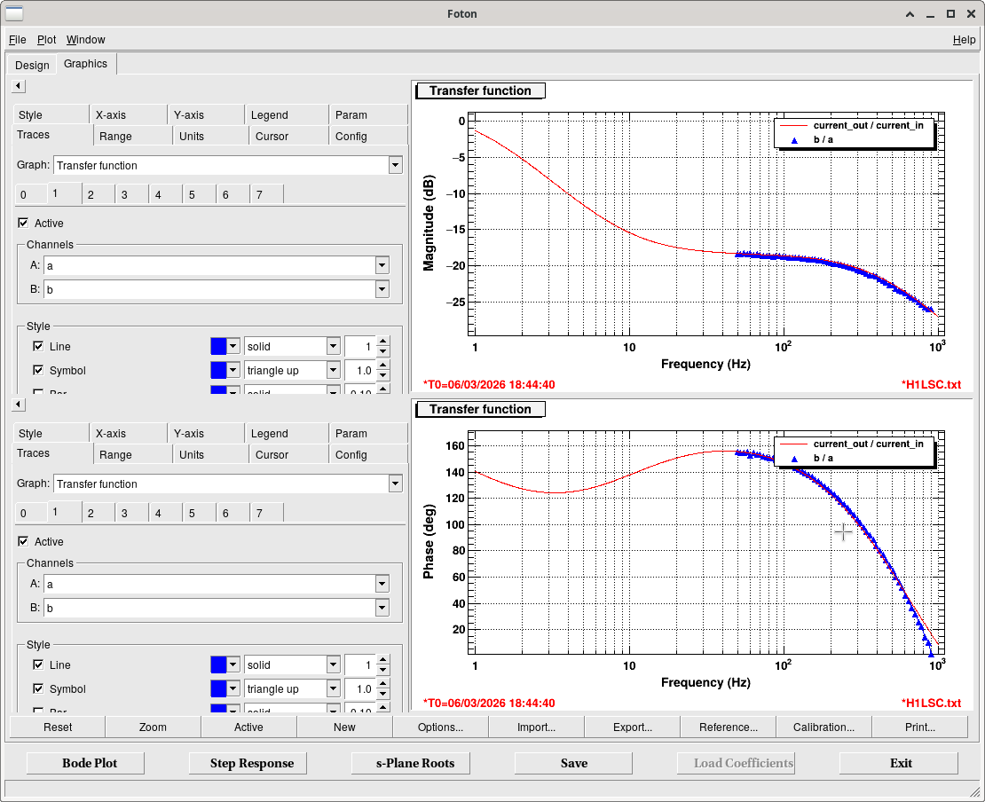
After locking the cavity with a provisional filter, the transfer function from L_SERVO_OUT to L_SERVO_IN1was measured and treated as the plant (see attached plot).
Since this plant includes both the optical gain dV/dl and the PZT actuator response, L_SERVO_IN1 was converted into meters using the calibration factor above before the measurement.
Also, the servo output is calibrated in V (and converted into cnts at the PZT_DRV filter). That means, the measured plant represents the transfer function from the PZT driver input to the actual cavity length actuation with the Unit of m/V
Plant model and actuator calibration
The optical gain and PZT actuator response are implemented in the servo model as FM9 and FM10 of L_SERVO.
In addition, a zpk(-800, 800) filter is included to emulate the phase delay.
The comparison between the model (FM9*FM10) and the measured plant (uncalibrated) is shown in the second plot. This response includes the PZT driver transfer function. That has two poles at 1 Hz and 400Hz, and one zero at 10 Hz. The DC gain estimated from the measured TF is 2.57 nm/V. This is comparable to the value measured with the scan of the JAC (2.97 nm/V).
Error signal normalization consistency
The error signal at JAC-L_SERVO_IN is normalized by the power at output of JAC_REFL_A_RF43. Therefore, once the guardian normalization procedure has been executed, the same calibration factor should remain valid.

Summary
The JAC cavity was locked in vacuum for the first time. Alignment was performed using the JM1 suspension and PSL PZT scan. After lock acquisition, the demodulation phase was optimized and a new Guardian state (NORMALIZE_SIGNALS) was implemented to automatically normalize several signals based on a slow PZT sweep.
Details
First in-vacuum lock
Demodulation phase optimization
Guardian update: NORMALIZE_SIGNALS state
Normalization steps
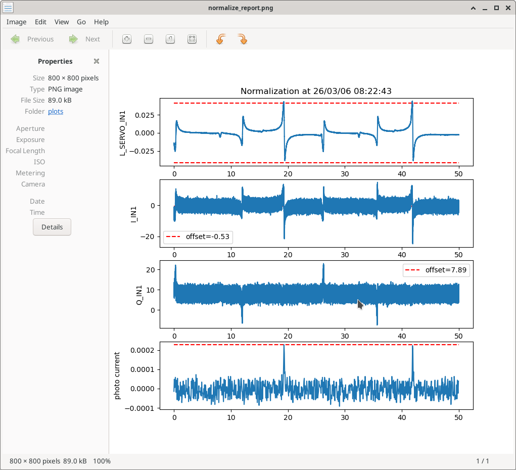
1. JAC_REFL_A_RF43 input offset
The median value of JAC_REFL_A_RF43_I/Q_IN1 during the scan is taken as the offset
The negative value is applied as the input offset.
2. PDH error signal normalization
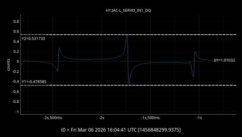
The peak-to-peak value of JAC-L_SERVO_IN1 during the scan is measured.
The signal is normalized so that the peak-to-peak becomes 1, by setting
REFL_A_RF43 filter gain = 1 / (max − min). The normalized signal is shown in the attached plot.
3. PZT scan trigger normalization
The peak photocurrent during the scan is measured.
This value is written to the Beckhoff channel JAC-TRANS_A_DC_NOMINAL to normalize the current signal.
4. Normalization report
A summary plot is automatically generated and saved as
/opt/rtcds/userapps/release/ioo/h1/medm/plots/normalize_report.png
You can open the plot from the button in the bottom-right of the MEDM screen