ALS Input Pointing QPD->PZT Loops
I started this fine Saturday checking the PZT alignment loops while JeffK measured SUS TFs. The idea was to make sure that the loops were fast enough to ensure that sub-Hertz alignment loops would not be bothered by sluggish PZT response. I found all of the loops in good working order with UGFs between 3 and 10Hz. While I was there I added cut-off and boost filters (loops are still unconditionally stable) and set all the UGFs a little closer to 10Hz.
SUS Damping
In search of something to blame for our large angular motion, much of which appears at 0.43Hz (the first longitudinal resonance), I measured the Transverse loop (side OSEM), which also has a resonance around 0.43Hz. It wasn't doing much, so I broght it up to speed with the Longitudinal loop boost filter. I also changed the cut-off somewhat, as there was very little phase margin for the highest resonance (near 4Hz). The result was a much more damped T DOF, but not much else that was obvious.
Slow Length Loop
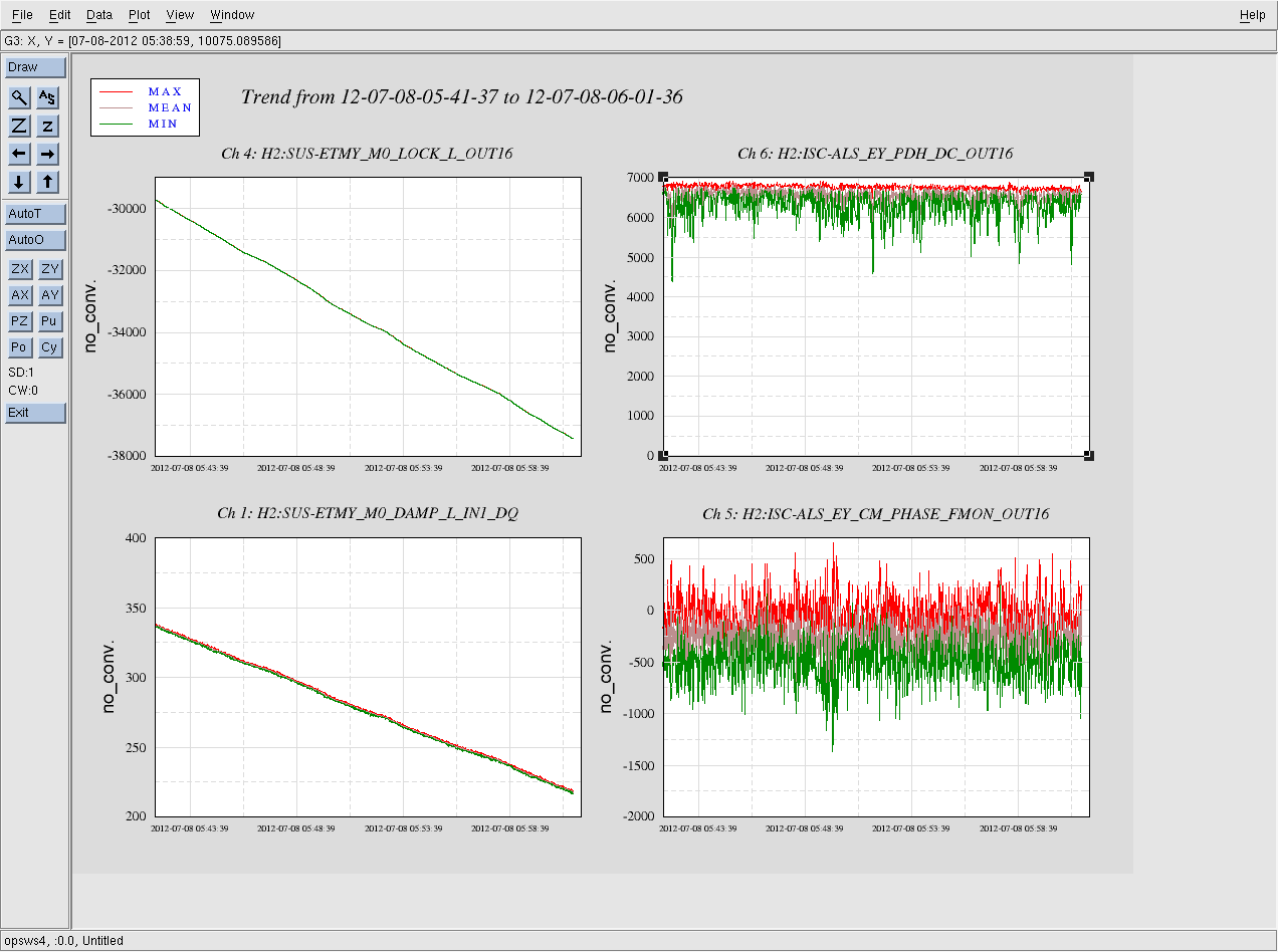
After figuring out that the PHASE and PDH fast monitor signals are switched in digital land, I was able to close a slow loop (< 100mHz UGF) which off-loads the VCO signal for locking the arm cavity to the ETM. At the moment, the locking filter is in the SUS-ETMY_M0_LOCK_L filter bank rather than the ALS_EY_ARM_LONG bank. This is because ETMY_M0_LOCK_L_IN1 is recorded at 2kHz, which is useful for making spectra (see below).
Calibrated Spectrum
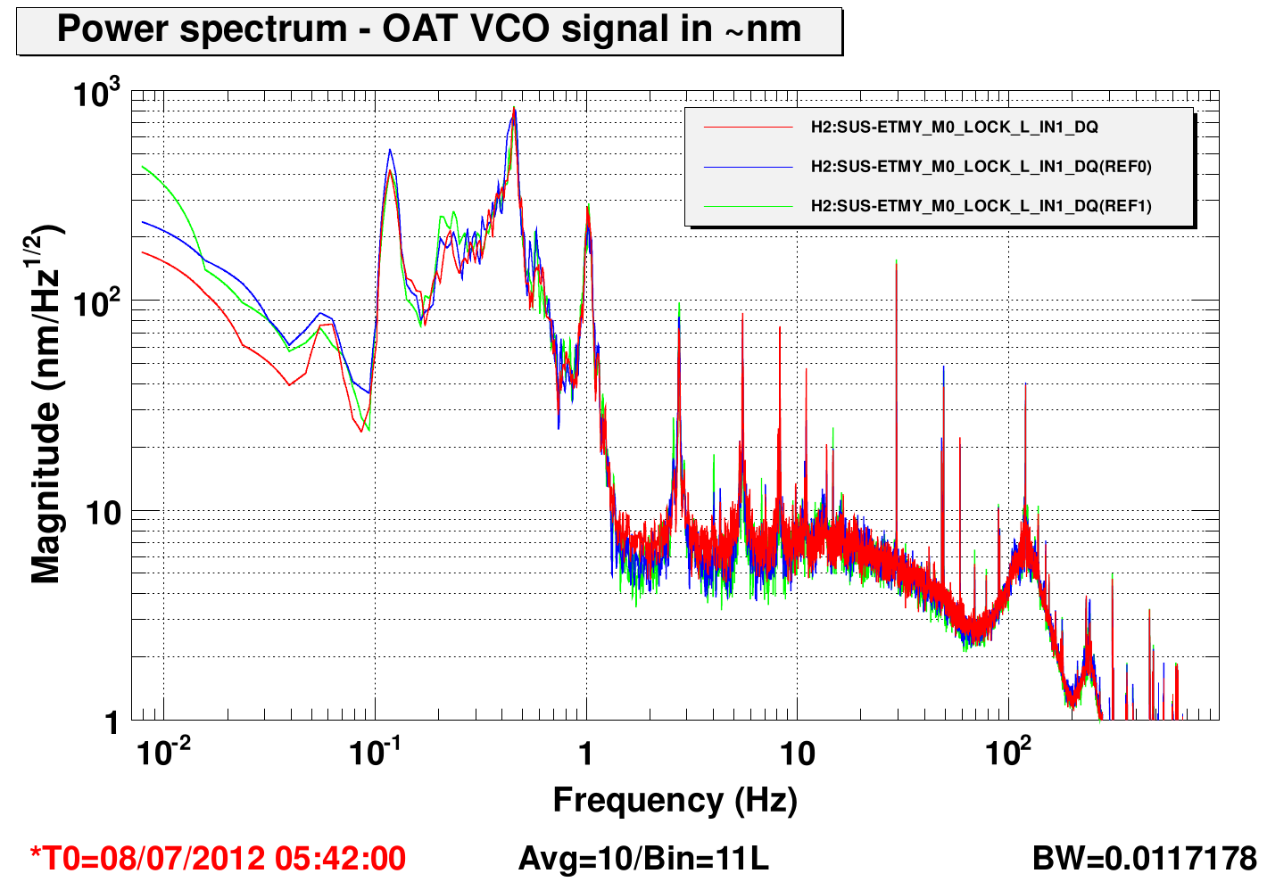
By stepping the gain of the slow loop after a large output had accumulated (with the input switch off), I was able to modulate the length of the cavity without unlocking. This modulation is visible in the signal send to the VCO for cavity locking, and in the ETMY M0 OSEMS, so I cross-calibrated teh VCO signal using 40nm/cnt as round number for the OSEMS (see fig 1). This gave 0.8nm/cnt for FMON, which might be 40kHz/V for the VCO if I got all of my conversions right... not so far from the 100kHz/V I would have guessed. I made 3 spectra from locks separated by ~1 hour, all of which overlap nicely (see fig 2).
Lock Stability
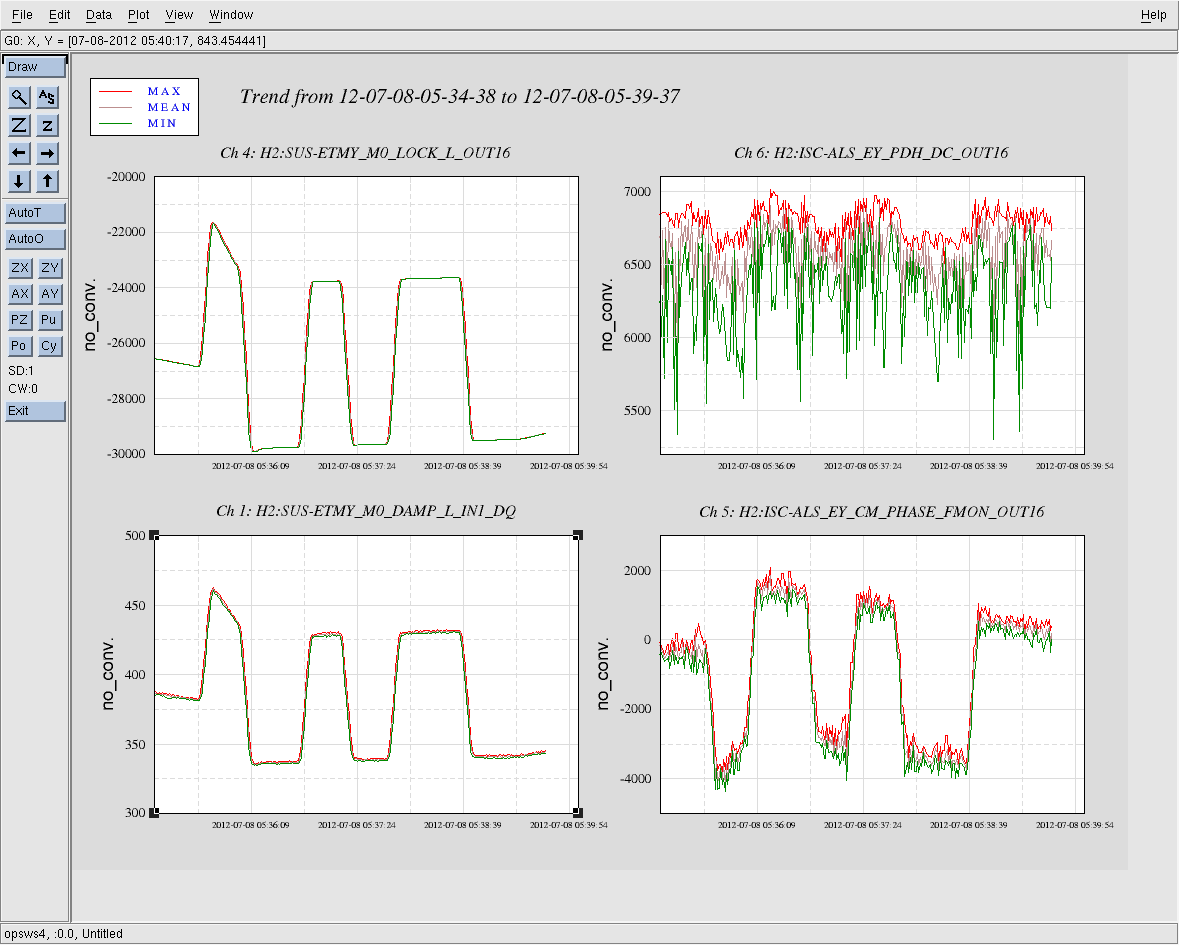
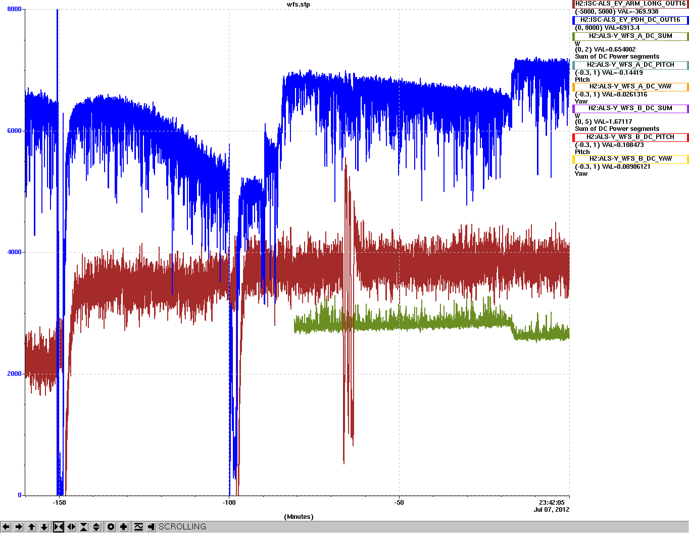
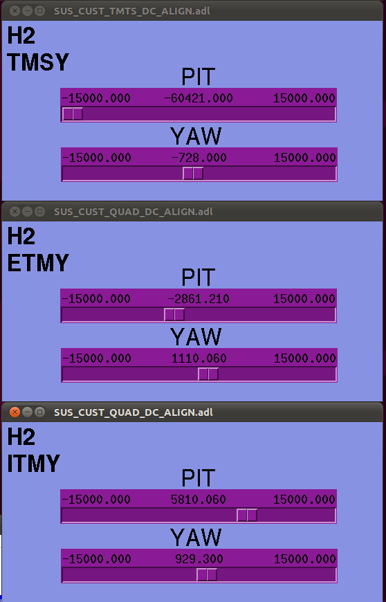
The main threat to lock stability was a large Long -> Yaw coupling that would misalign the cavity as the slow length loop pushed on ETMY_MO_LOCK_L. I fixed this with a small element in the drive align matrix (L2Y gain = 0.0036), indicating that we will probably have this problem with all of the suspensions just due to small magnet strentgh mismatches and BOSEM misalignments. With this in place, the cavity will stay locked for hours with ~10% power flucutions (see fig 3, 4). For reference, I include the alignment slider values in fig 5.
Calibration could be (and probably should be) done in the opposite direction, from VCO frequency/volt calibration to displacement.
M. Evans, (J. Kissel)

Just because we may (read: will most definitely) have to do it again, I called Matt and asked "How'd you come up with that 0.0036 L2Y coefficient for the DriveAlign Matrix?" Here's what he did:

- Look at DC Y Value (in DAMP IN1) with no L offset. (Say it's 1000 cts)
- Put a Huge L offset in place (through the TEST filter bank, for example), and watch Y change.
- Put a number into the L2Y DriveAlign matrix, and tweak until DC Y Value returns to what it was before Huge L offset.

Done! Easy-peezy, Japanese-y.

For the record, he says he also has a coefficient in place for L2P, but "[he's] not sure it's doing anything."
The "calibrated spectrum" shown above does not include a 1.6:40Hz pole:zero which are in the VCO. Doing this correctly will cause the spectrum to slope down between 1.6 and 40Hz... next time we'll include this, as well as the direct VCO calibration that Keita suggests.