For the evening shift, we set out to check the VCO calibration, and get some new calibrated spectra. This work starts where entry 3400 left off...
After relocking the cavity we found that he SR560 path (which was described in 3400 as having a gain of 10 at the SR560, and another gain of 10 at the TTIF) saturated due to low frequency motion (below 1Hz). With a gain of 1 on the SR560 it worked, and the 2 signal paths (SR560 and FMON) showed essentially perfect coherence. This also showed that the FMON calibration is not -20dB at DC and 20dB at HF, but rather 0dB at DC and 40dB at HF (see comment to 3400). With this direct measurement of FMON in hand, we removed the SR560 path.
Discussions with Bram brought out a missing factor of 2 in my previous calculation: since the PLL is in the 1064nm output of the laser, and we are using the 532 for locking, we get twice as much frequency change in the light seen by the cavity as the light seen by the PLL. (The same result can be achieved by ignoring the fact that green light is used at all, such that the conversion from frequency to length becomes L_cavity / f_laser = 3995m 1064e-9m / 3e8m/s = 14.2pm/Hz.)
In summary:
- The VCO + Frequency divider gives 139kHz/V at DC, with a pole at 1.6Hz and zero at 40Hz.
- At DC, the calibration for the FMON signal is 43.4Hz/count into the PLL.
- This gives 614pm/count for FMON as seen by the cavity.
- This is not very different from the 0.8nm/count found with the OSEM calibration in entry 3363.
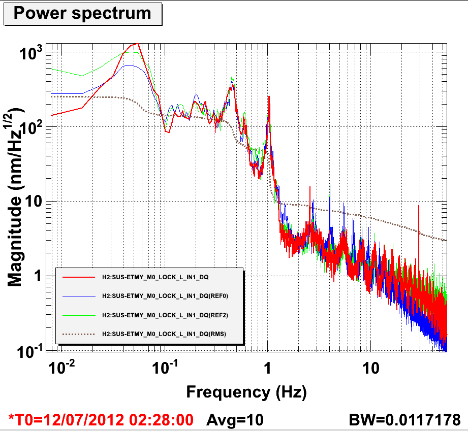
614pm/count using VCO, which is awesome. 0.8nm/count using OSEM, which is 30% off of the above.
Yet people keep saying that OSEM calibration should be fine at 20% level.
For people outside of the ISC:
1. Frequency offset between the refcav in the corner station lab and the EY ALS red beam is kept at the VCO frequency by a PLL loop.
2. Transfer function from VCO frequency to the red laser frequency is equal to G_PLL/(1+G_PLL) where G_PLL is the OLTF of PLL. Since UGF of G_PLL is about 20kHz, this is almost equal to 1 for f<1 kHz or so.
3. Electronics transfer function from VCO tuning input to the frequency of the VCO was measured to be H_VCO=139kHz/Volt *pole(1.6Hz)*zero(40Hz).
4. The green laser is the second harmonic of the red, therefore the transfer function from VCO tuning input to the green frequency is 2*H_VCO.
5. To lock the laser to the arm, we control the frequency of the green laser by feeding PDH signal via CM board back to VCO tuning input.
6. When the laser is locked to the arm, VCO input is equal to
v= (1+G_PDH)/G_PDH / (2*H_VCO) * df
where G_PDH is the OLTF of PDH loop and df is the equivalent frequency fluctuatoin of the cavity length, refcav and pll loop noise combined.
Since UGF of G_PDH UGF is 8kHz or so, again (1+G_PDH)/G_PDH is almost 1 for f<1kHz or so, therefore
v ~ df/(2*V_VCO)
7. Frequency to length conversion is 4000m/ 563.5THz (green light).
8. PDH CM board output is connected to PDH FMON channel, which has the transfer function of 2^15 counts/10 volt * zero(10, 10)*pole(100, 100).
Therefore, all in all, VCO input measured by FMON is calibrated back to length using
dL = FMON / (2^15 cts/10 V) *pole(10;10) * zero(100, 100) * 2*H_VCO * 4000m/563.5THz
= 602 pm/cts * FMON *pole(1.6;10;10) * zero(40;100;100).
Small difference in number (Matt's is 614 pm/V) came from the fact that I used 2^15/10 cts/Volt for ADC while Matt used the ADC calibration he did with his table top diode box as an amplifier.