Daniel, Keita, Richard, TJ, Kiwamu,
We found that the newly installed harmonic generator (35033) had different relative RF phase than the previous for all the harmonic frequencies with respect to the seed frequency 9 MHz (as pointed out by Daniel, 35038).
This impacted on interferometer's sensing demodulation phases at several places, making us unable to lock the interferometer.
We spent almost all the working hours today retuning the relevant demodulation phases. After retuning them, we managed to get back to full lock.
[Adjustment of demodulation phases]
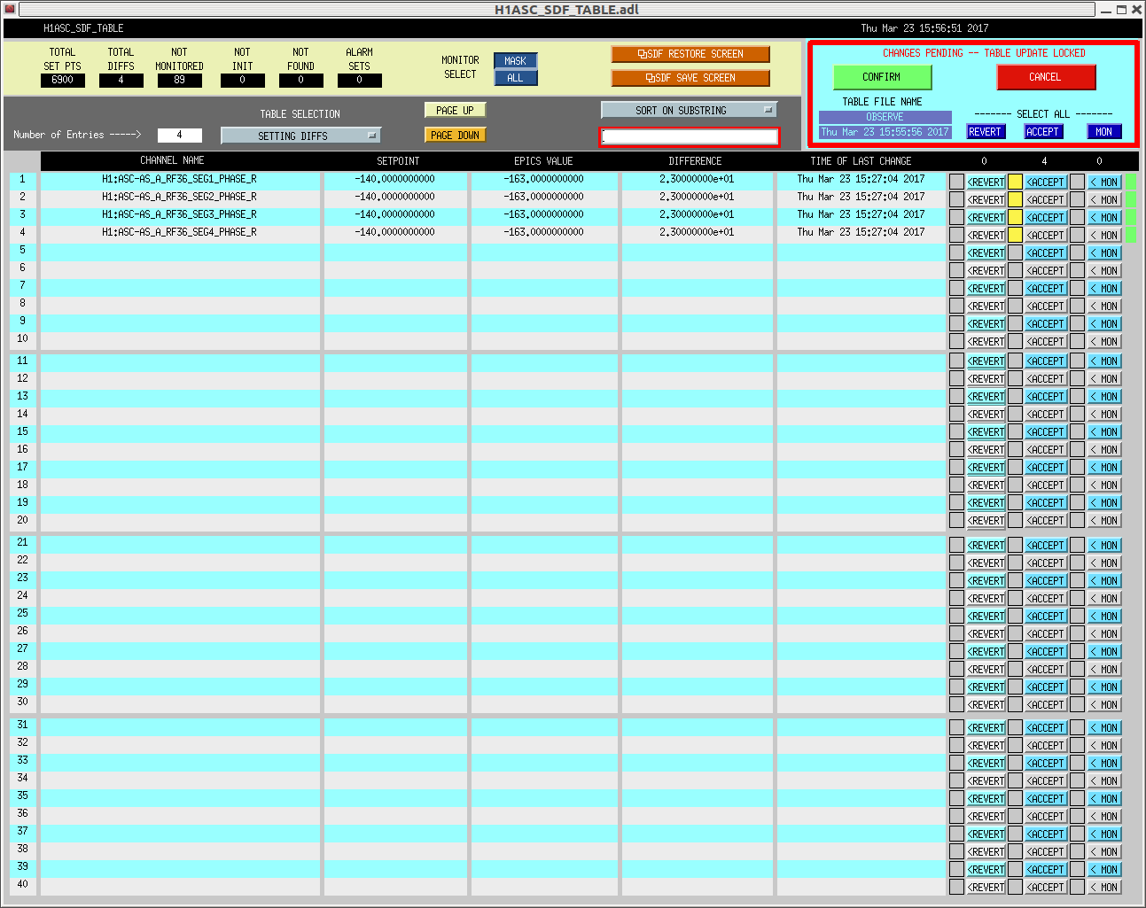
See the attached SDFs for a summary of the changes. Here is a list of the demodulation phases that we changed today.
- LSC-REFLAIR_B_RF27
- LSC-REFLAIR_B_RF135
- LSC-POPAIR_B_RF18
- LSC-POPAIR_B_RF90
- LSC-ASAIR_B_RF90
- ASC-AS_A_RF36
Even though we could have tuned ASC-AS_B_RF36, we decided not to do this today. According to ASC-AS_A_RF36 which needed to change its demodulation phase by -23 deg, a sensible thing to do is to rotate the AS_B as well by the same amount. However, because AS_B_RF36 is not in use in full lock and is used only for lock acquisition which went smoothly without changing the demodulation phase, we don't bother it for the moment.
REFL27 was adjusted by minimizing the PRCL contribution in its Q phase. REFL135 was adjusted by minimizing the SRCL component in its Q phase. The 2f signals (18 and 90 MHz) were adjusted to maximizing the amplitude in their I phase when the DRMI was kept locked with both arm cavities held at a off resonance point. ASC-AS_ARF36 was adjusted by minimizing the BS contribution in to its I phase.
[Adjustment of 3f input matrix]
As we adjusted the demodulation phases, we also went through checking the input matrix for the 3f signals for holding the DRMI. We have changed the REFL27I -> PRCL gain from -4.0 to -2.0 and the REFL27I -> SRCL gain from 0.6 to 3.2. The former was adjusted to match the optical gain of REFL9I and REFL27I by exciting PRM at 30 Hz with 10 counts. The latter was adjusted by minimizing PRM coupling into the SRCL signal with an excitation on PRM at 30 Hz with a 10 counts.
These changes are implemented in the ISC_DRMI guardian.
[Electronics measurement and some phase madness]
In addition to these adjustments, Keita, Richard and I went to the CER and measured the relative RF phase between the old harmonic generator unit and the new one for each harmonic frequency using an RF analyzer. With this measurement we attempted to determine the required demodulation phase changes before actually changing the demodulation phases ini the digital system. However this didn't really work out for the following reason.
We brought the old unit to the CER with us and powered it up right next to the newly installed unit. We then split the 9 MHz seed via an RF distribution amplifier into two and fed each of them to each harmonic generator unit. Then we measured the relative phase and amplitude of all harmonic pairs (e.g. 18 MHz from the old unit v.s. 18 MHz from the new unit). However, as it turned out later, the RF distribution amplifier had random relative phase between the outputs. This, of course, screwed up our assumption that the input of the two harmonic generators were synchronized in their phases. Since we didn't measure the relative phase between the two seed signals, the measurement helped only for figuring out the demodulation phases associated with the 45 MHz family.
Nonetheless, I post the measurement results here for the record.
| phi_new - phi_old | amplitude_new / amplitude_old | |
| 18 MHz | - 93 deg | -0.7 dB |
| 27 MHz | -19 deg | -9.0 dB |
| 36 MHz | 72 deg | -3.3 dB |
| 45 MHz | 103 deg | -1.6 dB |
| 90 MHz | 98 deg | -1.2 dB |
| 135 MHz | -21 deg | -2.0 dB |
Note that this measurement was performed before we changed the RF attenuates (35045).