aidan.brooks@LIGO.ORG - posted 09:30, Wednesday 05 April 2017 (35336)
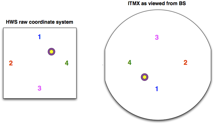
Orientation of HWSX coordinate system and location of point absorber on ITMX HR surface
I've attempted to orient the coordinate system of the ITMX Hartmann sensor relative to the ITM surface. The following analysis suggests that the coordinate system of the Hartmann sensor is flipped horizontally and vertically relative to the ITM, like so:
Determination:
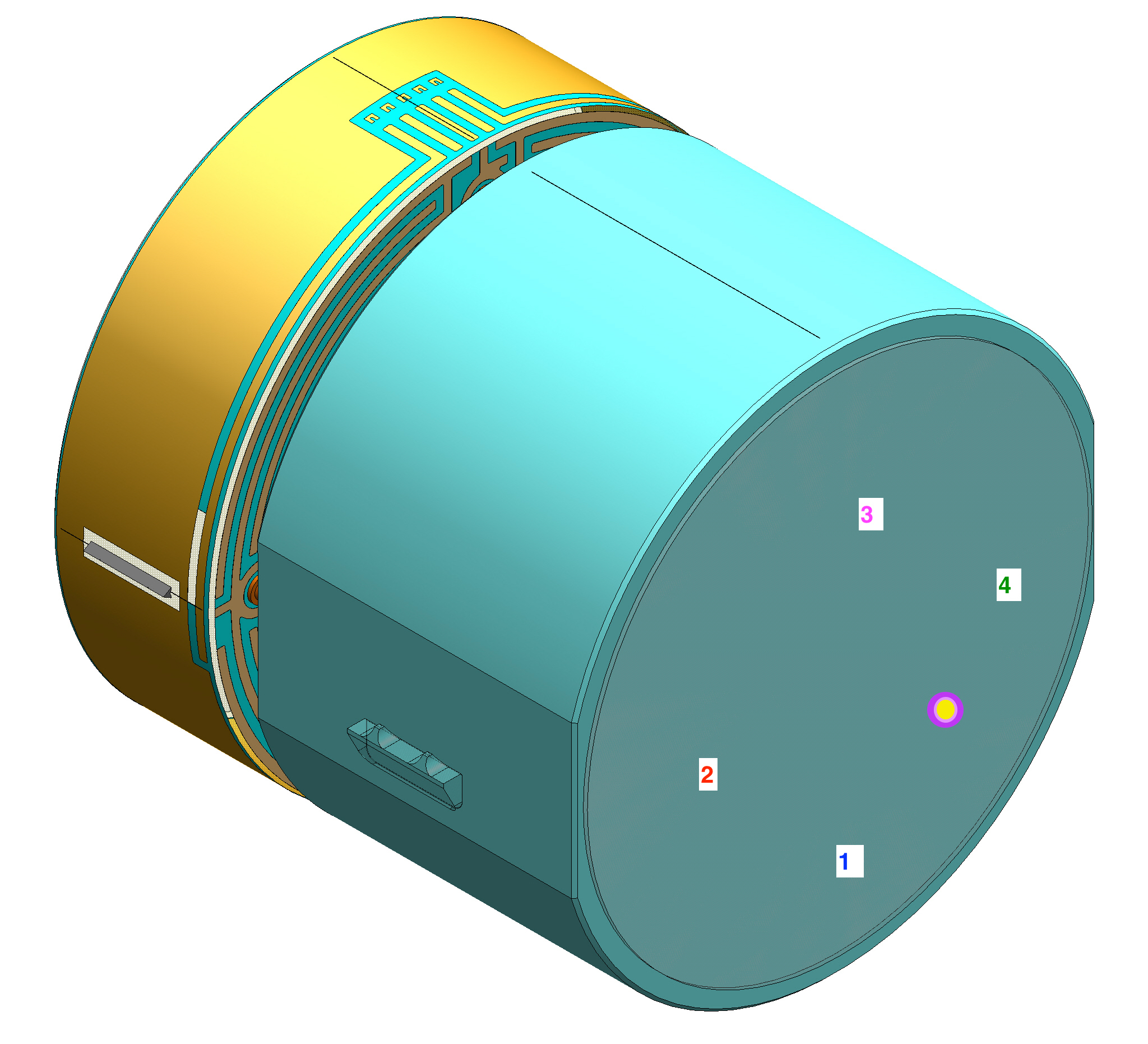
- The beam splitter baffle earthquake stops (which are at the top of the BS baffle) appear in the bottom of the HWS image (where the vertical pixel indices are low). Therefore, the HWS coordinate system is flipped vertically.
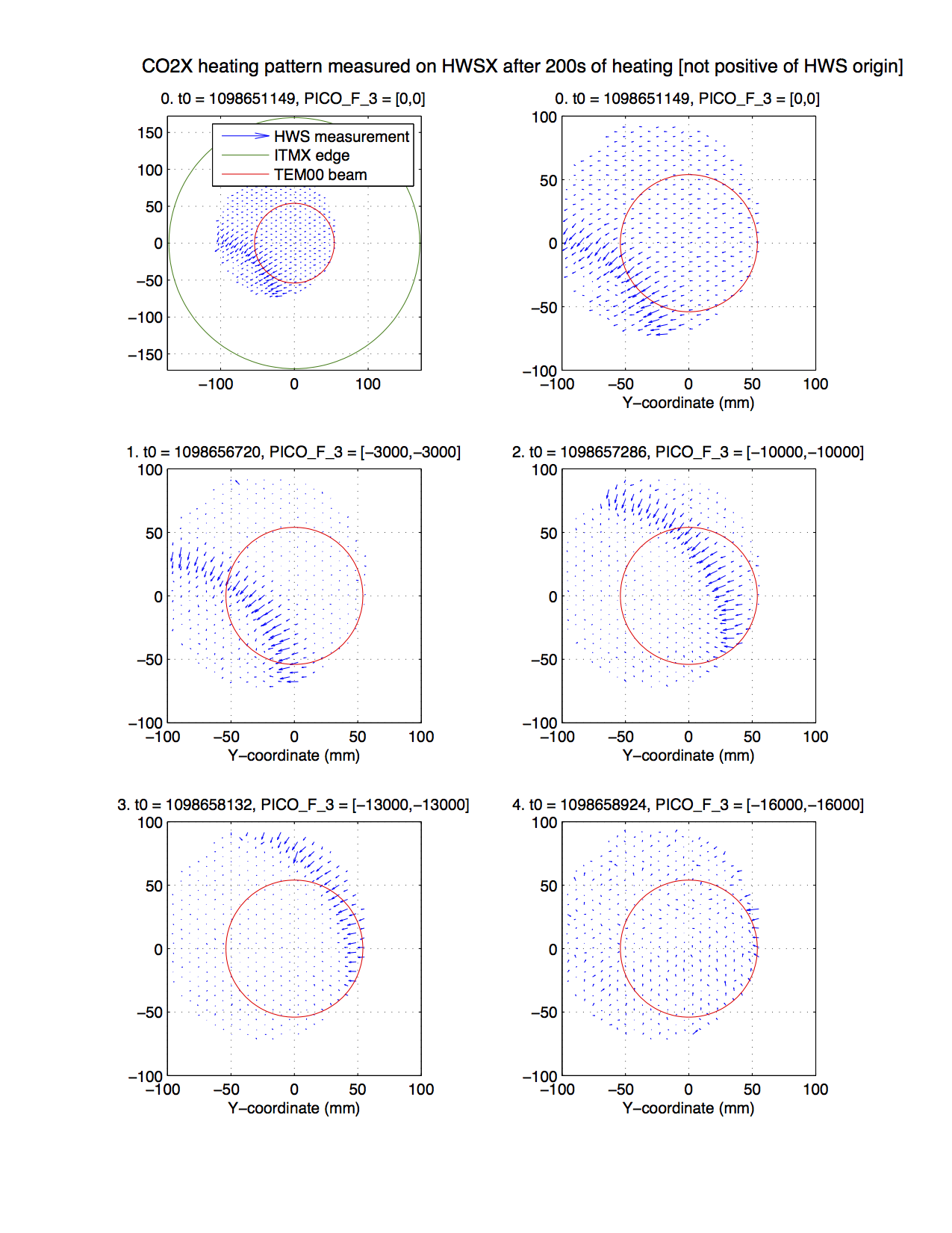
- Next, I used the motion of the CO2 heating beam on the ITM [aLOG 14714] as viewed by the Hartmann sensor to determine the left-right orientation. As the upper periscope mirror of CO2X is actuated, the CO2 heating beam moves across the face of the CP. We observed this with the HWS like so. Decreasing counts horizontally and vertically correspond to increasing values of the HWS coordinates horizontally and vertically.
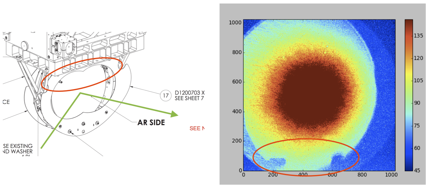
- That picomotor of CO2X is shown here. There are vertical and horizontal actuators. The pivot point is in the lower left of the mount as viewed here. The decreasing counts on the vertical picomotor correspond to increasing vertical coordinate on the HWS which corresponds to a decreasing position vertically on the ITM, which corresponds to a clockwise rotation of the vertical actuator in this picture.
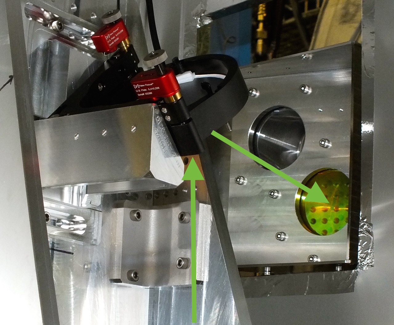
- For the YAW (horizontal) picomotor: the decreasing counts correspond to a clockwise rotation which will tilt the mirror to the left in the above image.
- The CO2 beam inside the vacuum system is folded in the way shown here. When the mirror is tilted to the left the beam tracks to the left across the CP (as viewed from the BS).
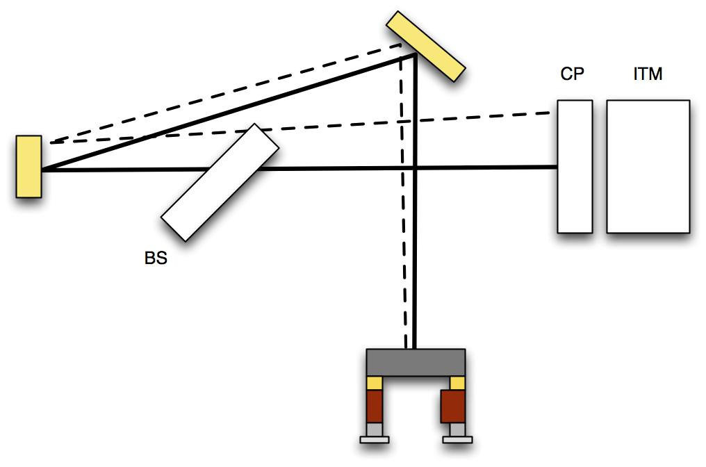
- Hence: the left hand side of the CP+ITM corresponds to the right hand side (or increasing horizontal coordinates) of the Hartmann sensor.
Finally, the point absorber appears in the upper right of the HWS coordinate system, so that means the lower left of the ITM (as viewed from the BS).

Images attached to this report