Yesterday morning I did a few tests of misaligning the OMC and putting excitations on the alignment loops. (see LLO alogs 32885 and comment and 28979 ). Depending on which method you use to estimate the normal RMS OMC alignment fluctuations, the OMC jitter noise is at least a factor of 2 below DARM or better.
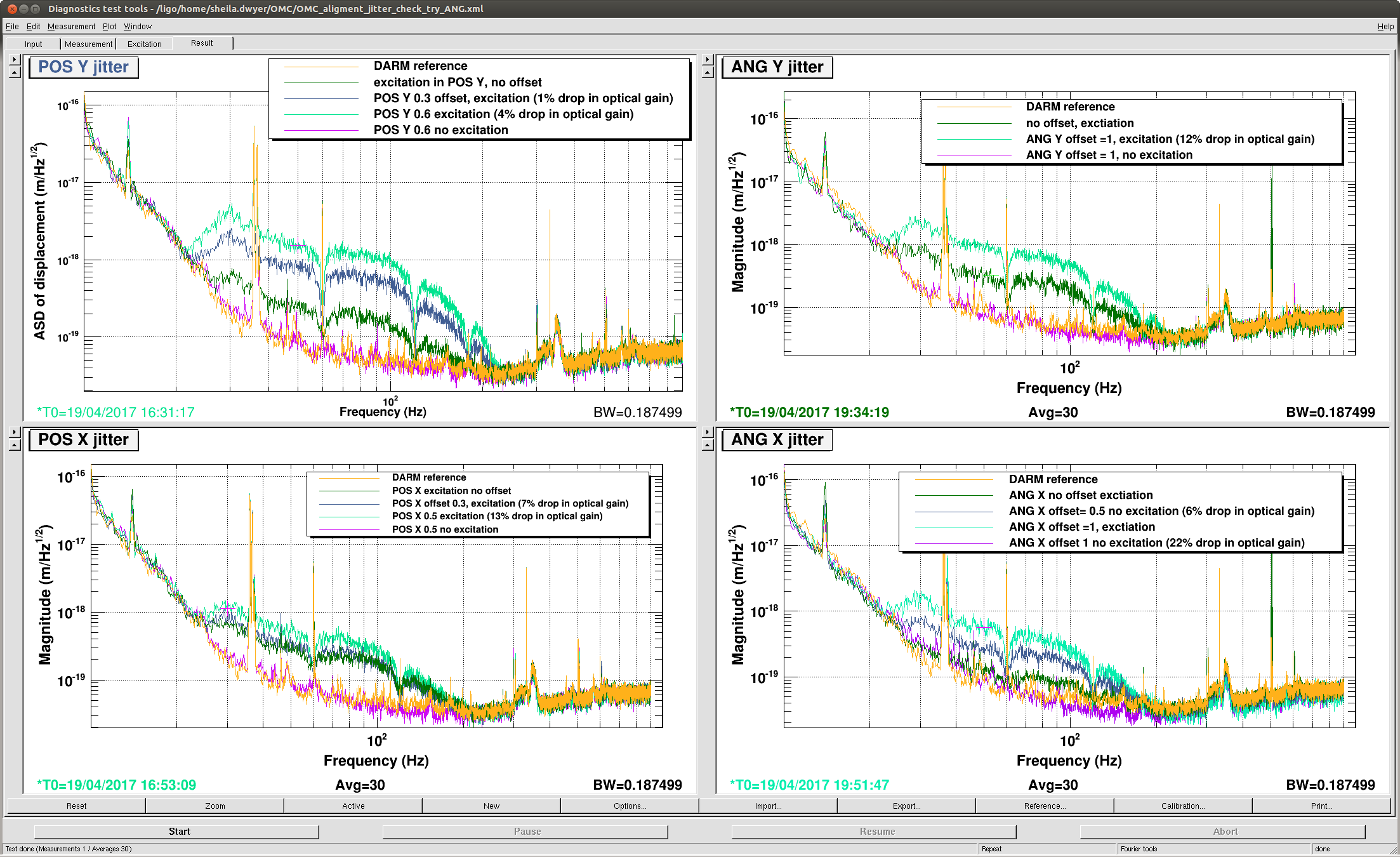
- Misalignments of the OMC did not produce any reproducible noise in DARM without an excitation (first attachment). The misalignments that I used are smaller than was recently used at LLO.
- There are three ways (that I know of) to estimate how large the offset was compared to the normal RMS alignment fluctuations: using the in loop error signal, looking at the motion on the QPDs, and the method that Koji described in his alog where the coupling from an an excitation is increased until it the coupling becomes linear and much larger than the coupling due to the normal alignment fluctuations.
| offset | optical gain decrease | coupling increase | offset/error signal RMS | QPD offset/QPD rms (A/B) | |
| POS Y | 0.6 | 4% | x5.8 | 10 | 60/56 |
| POS X | 0.5 | 13% | x2 (no coherence) | 10.4 | 80/62 |
| ANG Y | 1 | 12% | x2.6 (no coherence) | 5 | na/27 |
|
ANG X |
1 | 22% | x4.4(no coherence) | 17 | na/35 |
- According to the QPDs and in loop error signals, my offsets were large enough compared to the RMS that we don't need to worry about this noise source.
- The normal RMS fluctuations that I would estimate based on the change in the coupling of the excitation would be much larger, meaning that this test only assures us that this noise is below the level of DARM by the coupling increase factor.
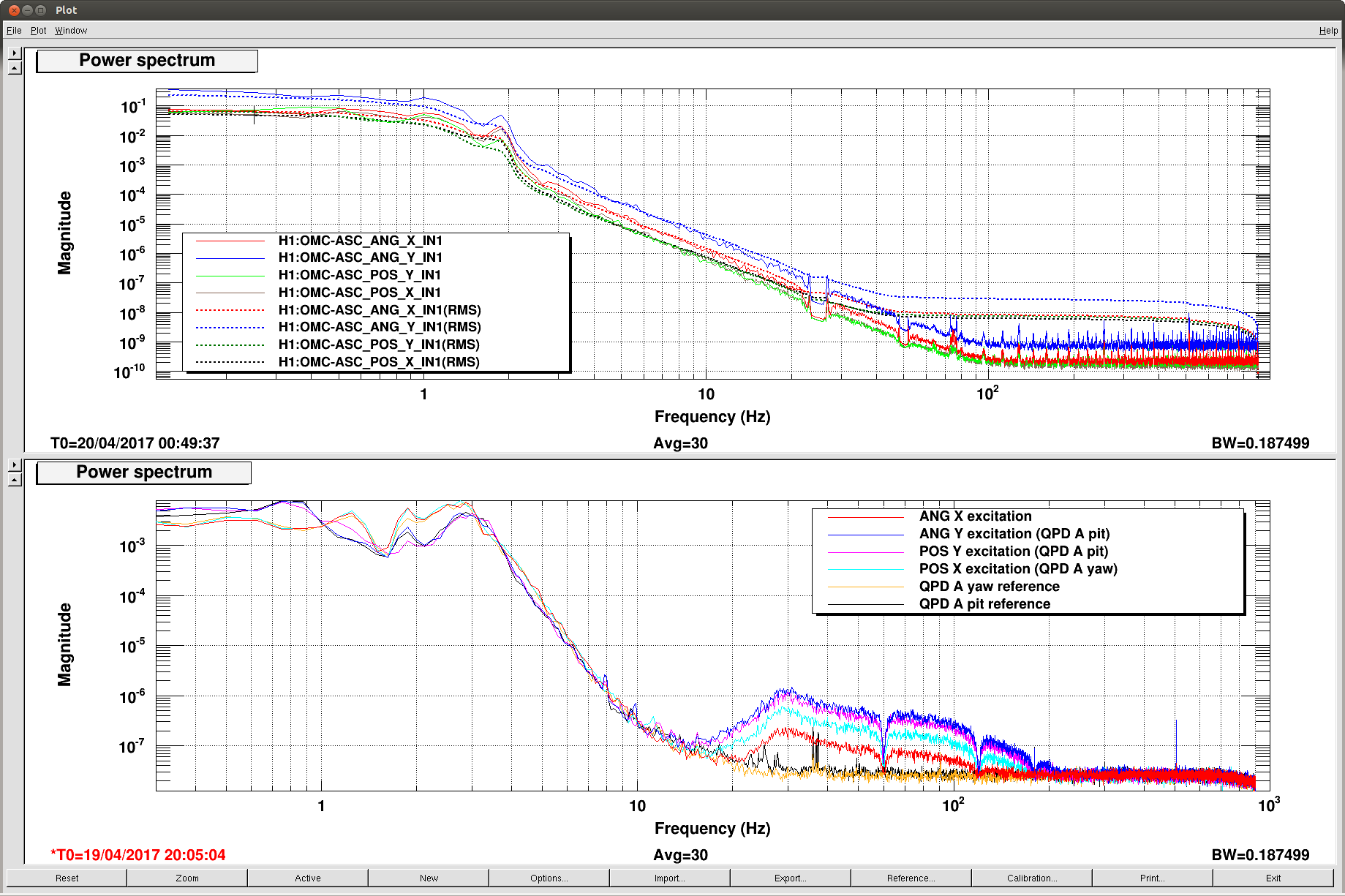
You can see that the behavior of POS Y is different from the other loops, this is the only loop where my offset was large enough to measure coherence between the excitation and DARM, but it was a small change in the optical gain. My excitations were not large enough to change the RMS seen on the QPDs (second attachment shows excitation sizes). Our OMC alignment loops are very slow, it takes 2-3 minutes for them to respond to a change in offset.
Some notes on what I think is implied in the LLO alogs:
When we are locked on DC readout the ratio of the optical gains for the misaligned/aligned OMC is the square root of what the ratio of transmitted powers would be if DARM were not locked on the DCPDs (thanks Keita):
- If we misalign the OMC when we are not locked on DC readout, the ratio of the transmitted power misaligned over aligned is (1-A).
- The power on the OMC DCPDs is held constant by the DARM loop, so the DARM offset changes from L0(aligned) to L1 (misaligned) (P=alpha L0^2=alpha(1-A) L1^2) This means L1=L0/sqrt(1-A)
- We can measure the ratio of the optical gain for the misaligned OMC/ aligned OMC (kappaC1/kappaC0=(1-A)L1/L0=sqrt(1-A))
My understanding of Koji's method for estimating the rms: (Delta theta is normal alignment fluctuations, dtheta is the excitation, and theta0 is the offset. )
- Normal contribution to DARM noise is proportional to DeltaTheta^2 (should be smaller than DARM, gold is upper limit)
- Contribution to DARM noise with excitation but no misalignment is proportional to dtheta^2+2dTheta*DeltaTheta (forest green curves in first attachment) (DARM will not be coherent with the excitation in this case)
- Contribution to DARM noise with offset but no excitation 2*DeltaTheta*theta0 (should be small, fuchsia curves would be larger than gold reference otherwise)
- excitation and offset- (2)+(3)+2theta0*dTheta (mint green curves) (DARM will be coherent with excitation if this term dominates over DeltaTheta*dTheta)
I think that what Koji is doing is taking the ratio of (4)/(2) (coupling increase in the table above) and estimating that that is the ratio of the offset/normal RMS.