volker.quetschke@LIGO.ORG - posted 16:44, Wednesday 01 August 2012 (3691)
Modulator swap and optics re-alignment in the PSL
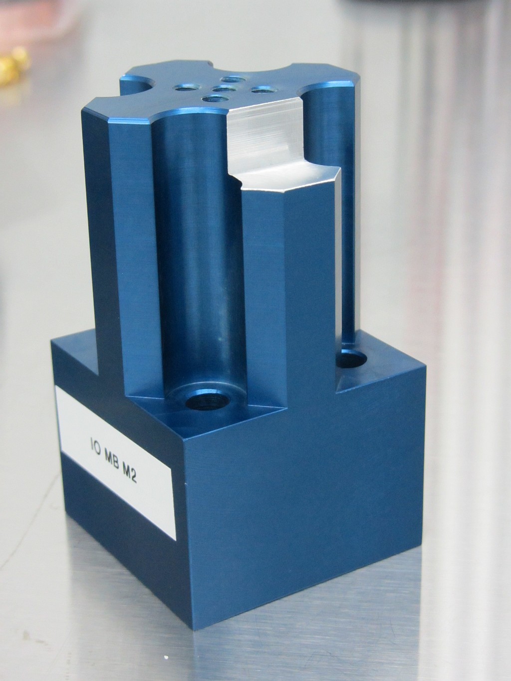
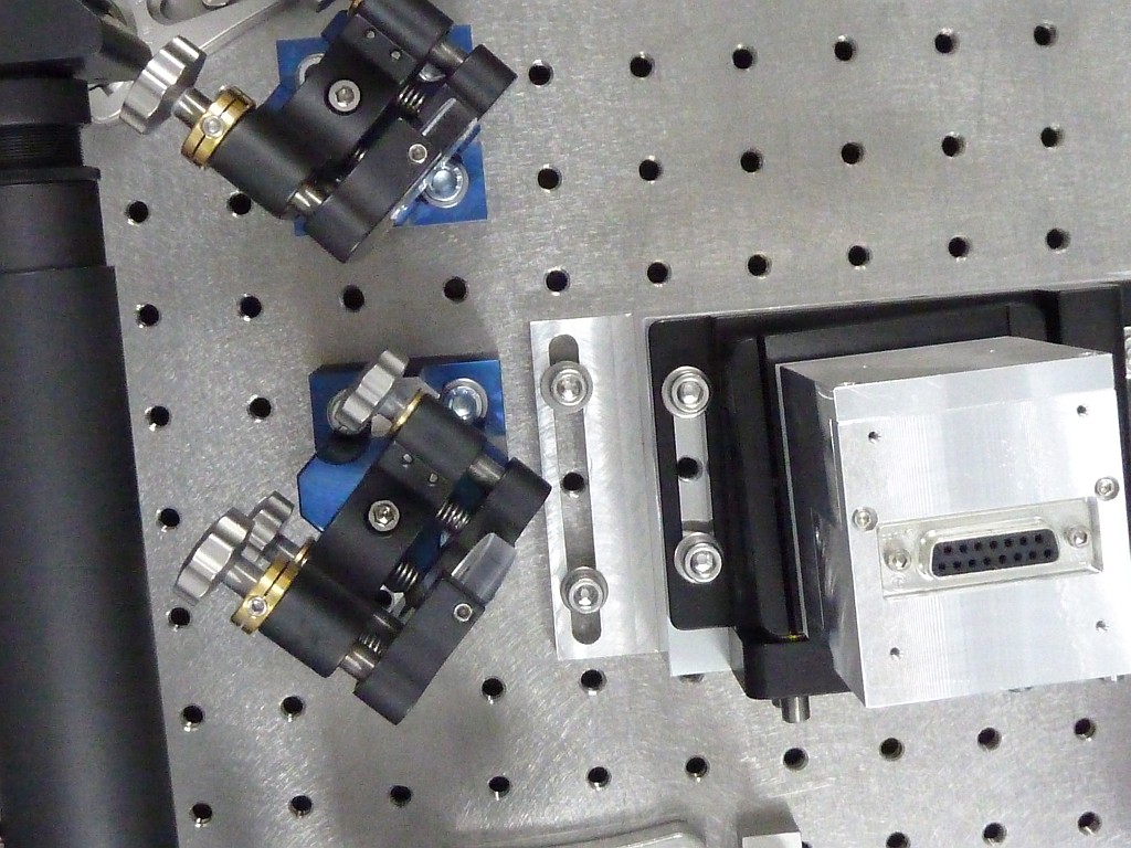
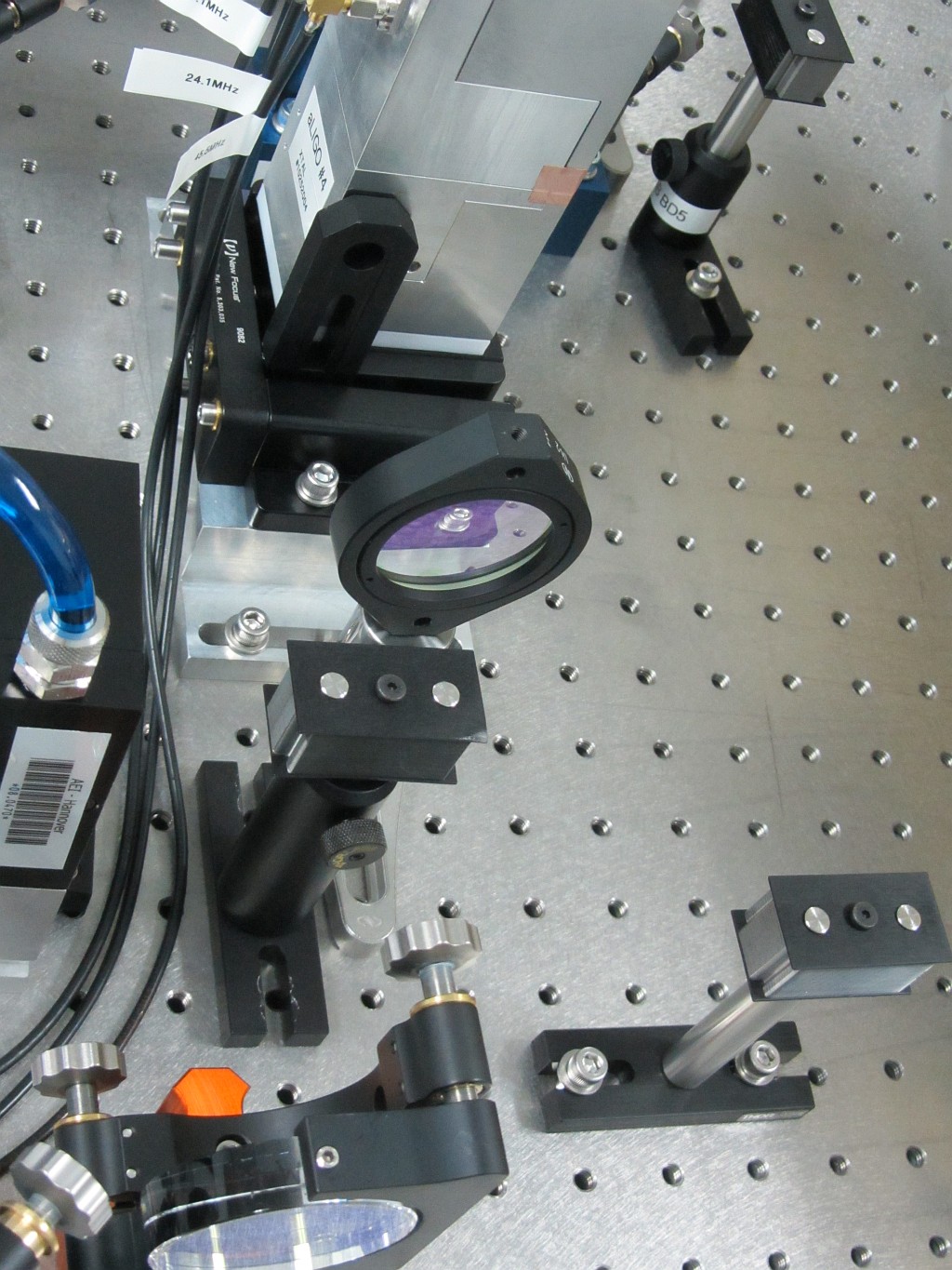
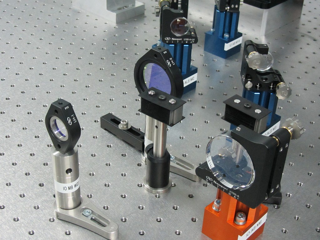
[Michael R., Cheryl V., Volker Q.]

The H1 modulator has been installed on the PSL table, the temporary H2 modulator
got swapped out.  The H2 modulator will be re-tuned and become the H1 spare.

The beam after the modulator was not parallel to the grid on the optics table
because IO_MB_M2 was not movable far enough to allow for the about 5 degrees
of beam deviation going into the EOM.

At LLO this problem was solved by using a New Focus Pedestal Base with
Clamping Forks and moving mirror to an off-grid position.

Here we decided to use a mirror mount with three adjustment screws and
a modified blue base to mount IO_MB_M2.  This provided a stable mounting
the mirror mount and the needed flexibility to steer into the EOM.
All IO PSL optics were realigned using pinhole 4 inch beam height apertures
to keep the beam on the grid of the optical table.

We also found that the reflections from the AR surfaces of the mode
matching lenses IO_MB_L1 and IO_MB_L2 were surprisingly strong.
(We followed various stray beams with 10W into the EOM)

The immediate reflection from IO_AB_L1 hits the brushed aluminum
surface of the modulator housing - the lens is turned slightly to
not reflect the beam back into the modulator.
This creates a wide horizontal "spray" of scattered light because of
the brushed surface.  We worked around this problem by placing a dog
clamp beside the EOM aperture. See picture (dog_clamp_and_beam_dump.jpg),
this works, but is certainly not a permanent solution.

The next beam we blocked was a reflection from IO_MB_L2 partially hitting
the rim of IO_MB_L1 and partially going trough hitting the dog clamp
area.  See the razor blade dump roughly in the center of the dog clamp
picture.

Another beam we blocked was going towards IO_MB_L2, see (L2_dump.jpg).
(At the time of writing this we are not sure anymore if this beam was
already blocked by the dump in front of IO_MB_L1, this needs
verification).

Finally we placed a razor blade dump close to IO_MB_M3 to catch the
wrong polarization in the separated beam coming from the modulator
crystal.  See picture (wrong_pol_bd.jpg)

Sideband strength and RFAM will be reported in a separate log entries.
Images attached to this report