jeffrey.kissel@LIGO.ORG - posted 00:11, Friday 07 July 2017 (37361)
Violin Mode Damping at ~1.5kHz
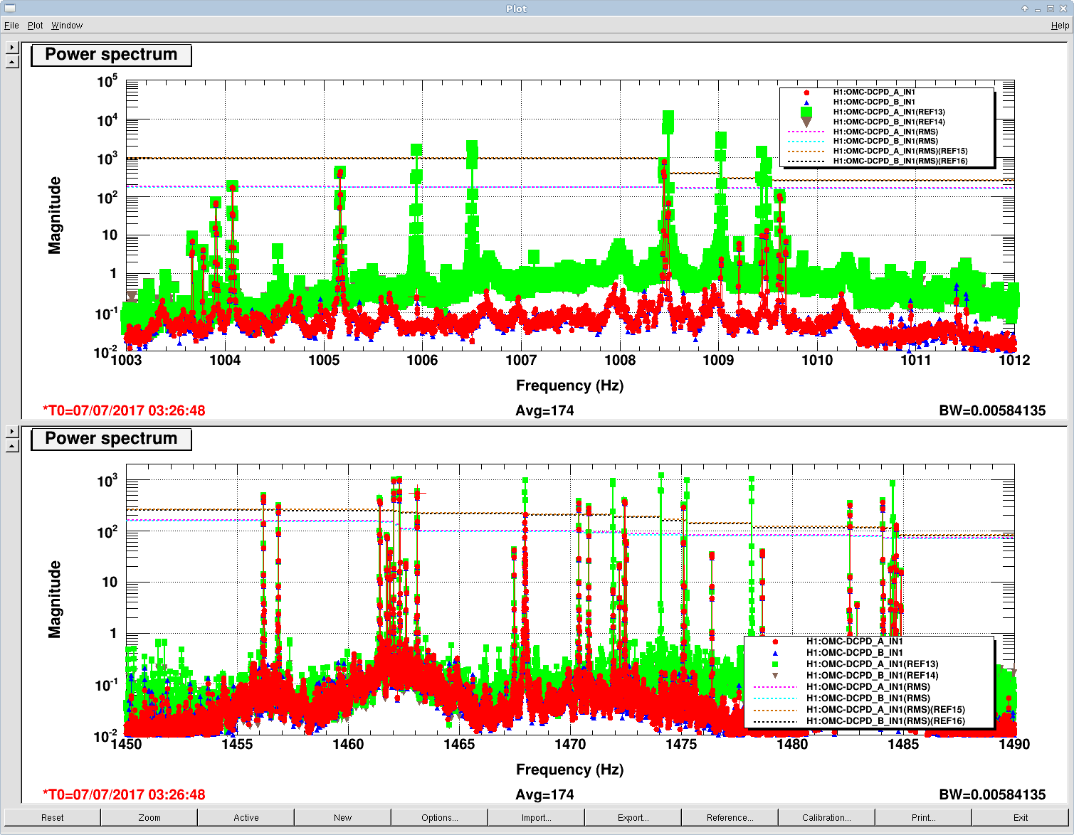
J. Kissel, C. Vorvick

We spent the remainder of the shift trying to damp violin modes as best we could with the IFO in DC readout, but with no stages of DCPD whitening. We were able to reduce the RMS counts of ADC input on the DCPDs by about a factor of 5, by performing all the already known violin mode damping tricks for the fundamentals (~500 Hz) and 2nd harmonics (1000 Hz), as per Nutsinee's glorious work on the sacred LHO violin mode table. However, this earthquake has rung up *every* harmonic.

So, I begun the task of developing filters to damp the previously-undamped 3rd harmonics. I took a few hours of play, but I was able to known down the 6 highest RMS contributors, but there's still plenty more to go. I've added new rows to the violin mode table that detail the configuration and filters I created, but I summarize here:

EX      1478.17      MODE 1     FM 4 6 7, G = -1000
EX      1475.25      MODE 2     FM 4 6, G = -1000
EX      1474.08      MODE 3     FM 4 6 8, G = -2000
EX      1471.93      MODE 5     FM 4 6 7, G = -2000
EY      1484.53      MODE 2     FM 4 6 8, G = +2000
IX      1467.96      MODE 1     FM 4 6 7, G = -2000

These details may change over time as we consolidate filter banks, so always treat the violin mode table as cannon, not this aLOG.
Note that all of these settings are for a 30W, DC readout IFO, with PUM coil drivers set to State 3, and driving in Pitch.

The filter design process at 1.5k has become pretty straight-forward:
- Have a "live" (3 avgs, exponential) DTT spectra of H1:OMC-DCPD_A_IN1 and H1:OMC-DCPD_B_IN1 going with RMSs of each and a reference plotted for all (like I have attached). 0.005 Hz BW, so you can nail down which mode you're attacking. (Pick the one that's contributing the most to the RMS in the 1.5 kHz band).
- Also have a live DTT spectra of H1:DARM_IN1_DQ going, at faster pace (I chose 0.02 Hz BW) for use while tuning the gain and phase.
- Copy the 1.5k set to a new empty filter bank (thanks for that now-essential feature Jim Batch!)
- Adjust the frequency of the bandpass to be centered around the mode you're trying to attack. I've been successful with ~0.3-0.5 Hz bandwidths. Note, once I have a bandwidth I like (where my figure of merit is "how fast is the phase wrapping?" I shoot for less that 3-4 phase wraps in the bandpass frequencies), I shift the bandpass up or down such that the phase at the exact frequency of the mode is 0 +/- 5-10 [deg].
- Adjust the "-60 deg" filter by highlighting the zpk portion, hitting the ZPK button, switching to Mag/Phase, then adjusting the frequency of the complex pole (i.e. add new, and remove old) by 10-50 Hz until I get -60+/-5 [deg] at the mode frequency. I make sure to then normalize the filter to 1 at the mode frequency when I get the right poles.
- Adjust the "+60 deg" filter in the same way, just shooting for +60+/-5[deg]. Remember to normalize to 1 a the the desired mode frequency.
- Save the foton file, load it into the bank.
- Turn on the bandpass, and set a gain, watching the output of the filter bank on a StripTool.
- Start with gains of 10-100, but you won't see action until about a gain of 1000.
- Change the sign and phase as normal to find which combination creates damping.

Design at 2k and 2.5k should be pretty darn similar, once you make a starter band-pass and +/-60 deg phase filters.

The attached shows the result of our work at 1k and 1.5k this evening.

I left all of the damping filters I've designed on and running. These should get blown away if we lose lock, so now harm done. Plus there's always the SDF system.
Images attached to this report