J. Kissel
Still hunting for what's limiting our range, we took Valera's suggestion to drive stage 2 (ST2) the test masses' BSC-ISIs to check for, among other mechanisms,
(a) scattered light problems,
(b) charge coupling issues, or
(c) mechanical shorting / rubbing
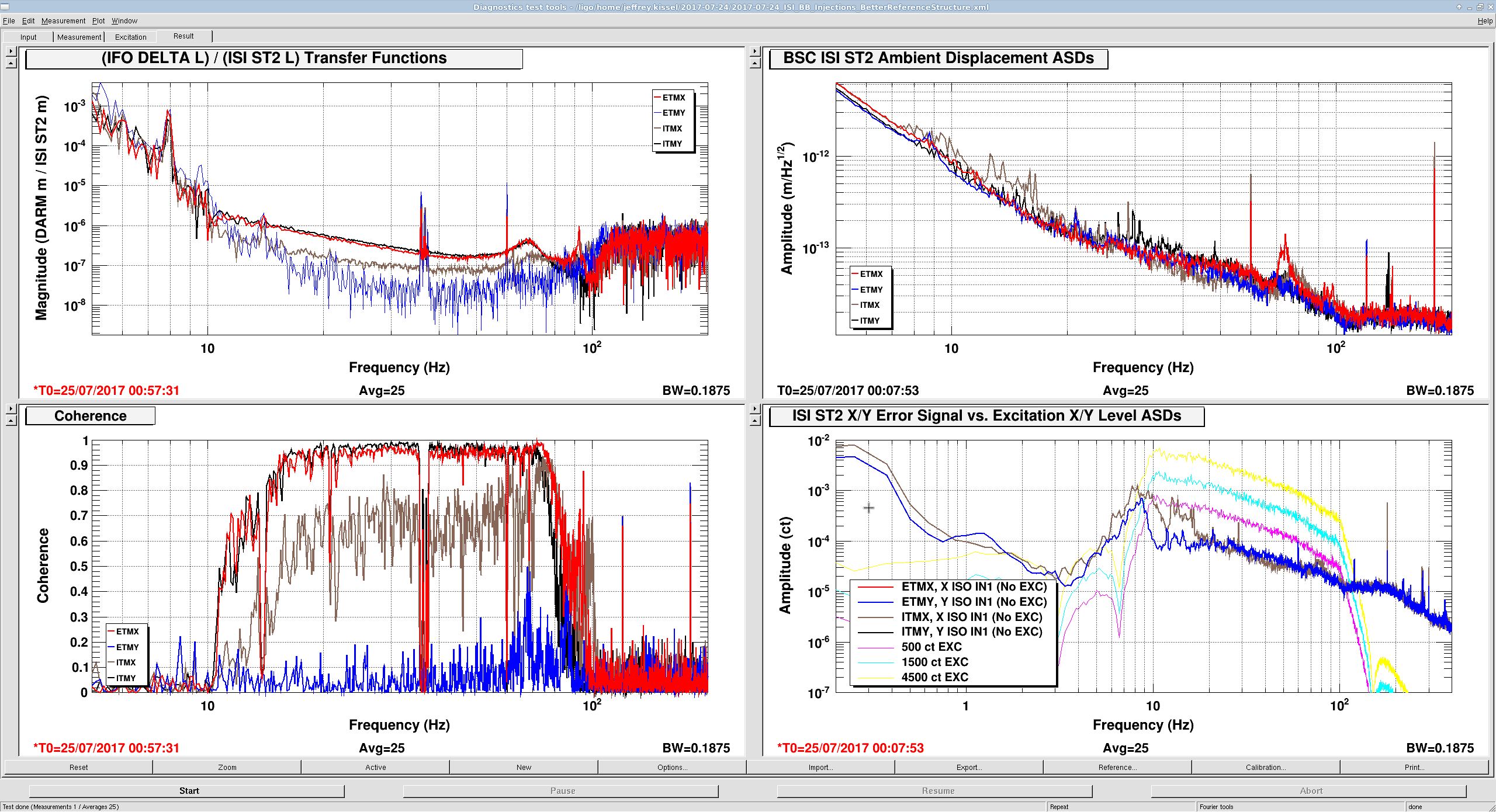
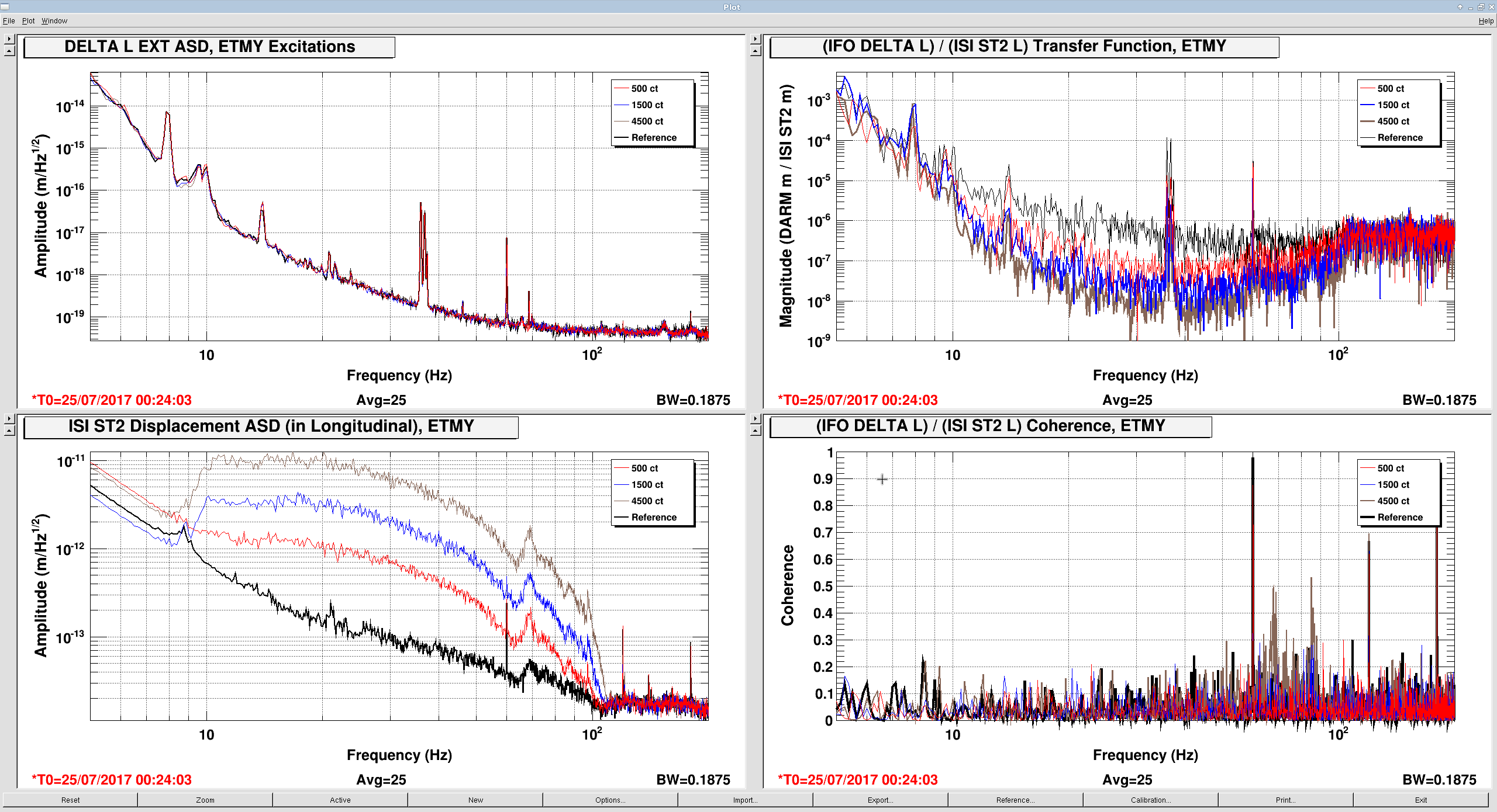
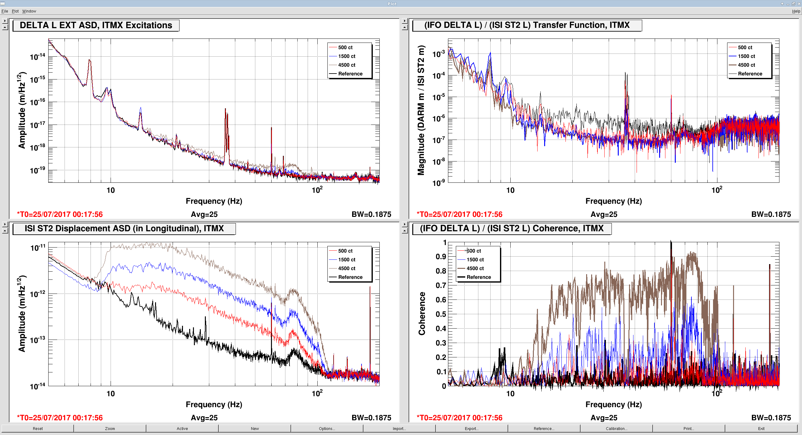
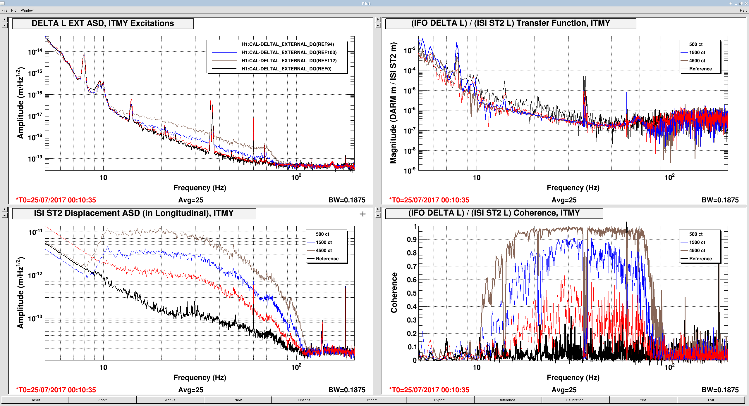
The measurements indicate that ETMX and ITMY are the worst offenders, in that their ambient noise falls as ~1/f^{1/2} between 10 and 100 Hz, with some resonant features at 70 and 92 Hz. The features are presumably the first few cage bending modes, for which we have Vibration Absorbers that have already knocked down the Q of the ~70 Hz modes, thankfully.
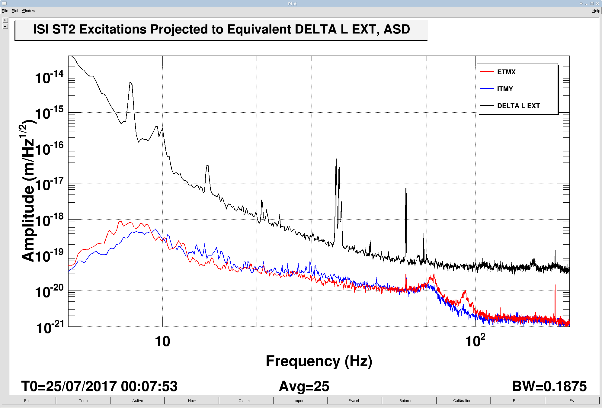
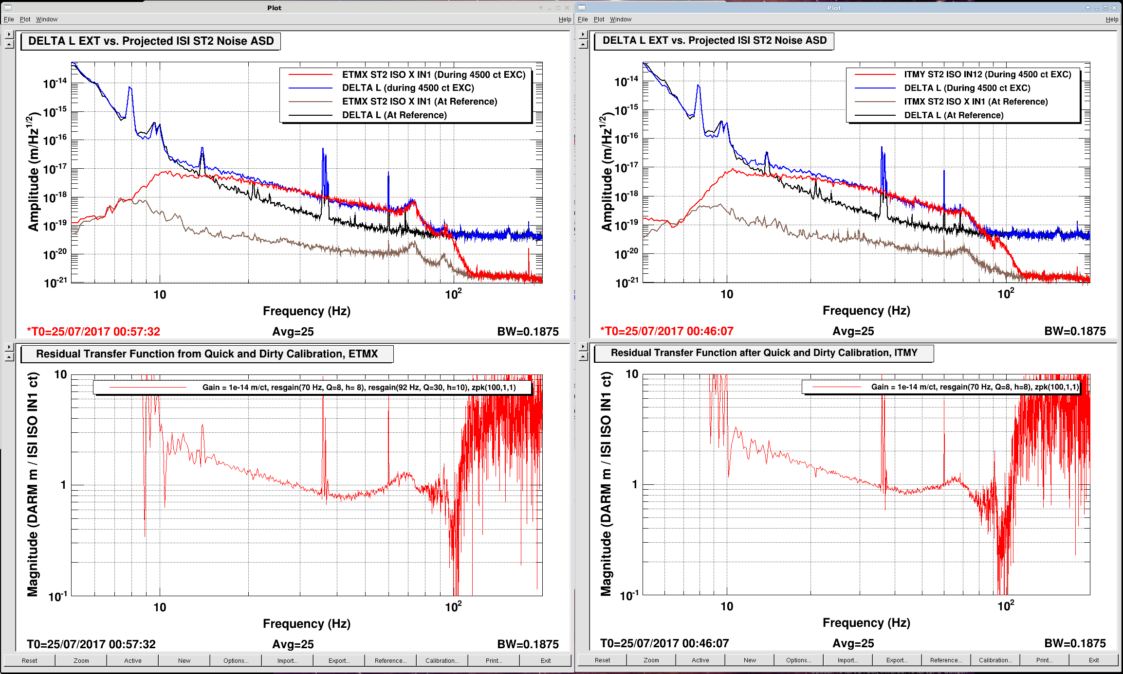
I've used the measurements to "calibrate" the error point of the ISI's ST2 Isolation Loops, and project the ambient noise to equivalent DARM displacement noise (a.k.a. primitive noise budgeting), see first attachment.
Each come within a factor of 3-5 at their worst parts during ambient conditions; too close for comfort.
Also, of course, there should be no such coupling at all if the cage were properly isolated from the suspension, and this appears to be a straight-forward linear coupling.
Note that the precision of the projection is not great -- I did not try hard to get it right. There are addendum plots that show the residual between model and measurement.
I don't think this is a / the limiting source now, since there is little coherence during ambient conditions, but this will certainly be a problem in the future if the coupling remains this bad for ETMX and ITMY. It definitely deserves a more careful calibration, further study with other degrees of freedom, and mapping out a broader frequency band. Perhaps we should check the coherence with these ST2 ISI channels after Jenne's subtraction of jitter (see LHO aLOG 37590) -- though the slope doesn't quite match up (from eye-ball memory).
ITMX's coupling is about 1/2 as bad, and ETMY does not show any visible signs of bad coupling at this excitation level (which is damning evidence that it's related to charge, since ETMY has the largest effective bias voltage at the moment).
%%%%%%% Details %%%%%%%%
Measurement Technique (all while in nominal low noise):
- choose obvious, simply to imagine coupling degrees of freedom: the longitudinal axis for the optics in the arm cavity (X for ETMX and ITMX, Y for ETMY and ITMY)
- measure ambient error signals in those directions using DTT.
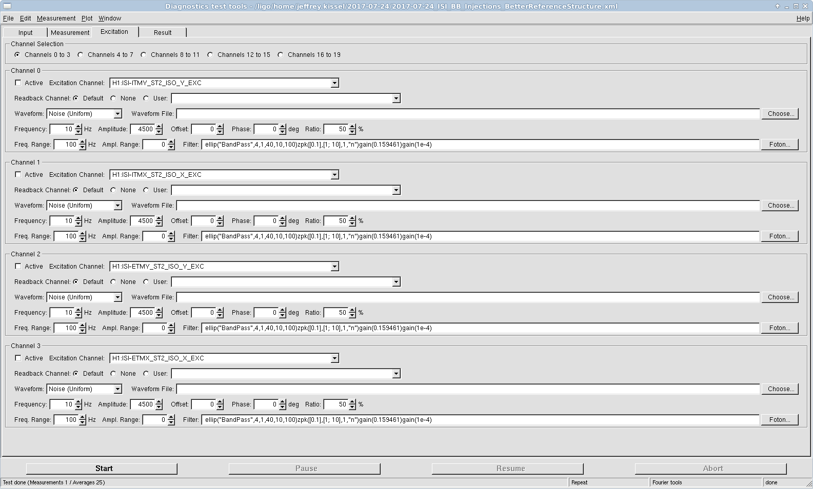
- In the same DTT template, create a band-passed excitation where you suspect you're having problems (10-100 Hz), shape it to look roughly like that ambient spectra you see. I used
ellip("BandPass",4,1,40,10,100)zpk([0.1],[1; 10],1,"n")gain(0.159461)gain(1e-4)
copied and pasted to the 4 excitation banks (thanks Daniel!) so that I can pick and chose what I'm driving, and with what amplitude.
- Grab a bunch of relevant response signals; the excitations, the error signals, the calibrated displacement (the pre-calibrated SUSPOINT signals are especially nice -- though the suffer from spectral leakage up to above 10 Hz).
- Slowly creep up the drive (I started with 0.001 [ct] to be extra careful) until you start to see hints of something / coherence.
- In case the coupling is non-linear, record the results at three different drive levels (I chose factors of three, 500 ct, 1500 ct, and 4500 ct, filtered by the above band-pass.)
Analysis Techniques
- Remember, to calibrate DELTA L EXTERNAL, one must apply the transfer function from
/ligo/svncommon/CalSVN/aligocalibration/trunk/Runs/O2/H1/Scripts/ControlRoomCalib/caldeltal_calib.txt
i.e. copy and paste that file into the "Trans. Func." tab of the calibration for the channel, after creating a new entry called (whatever) with units "m".
- For calibrated transfer functions of ISI displacement in local meters to DELTA L in global differential arm meters, just plot transfer functions between SUSPOINT motion (which comes pre-calibrated) and DELTA L EXT.
- Store the transfer function between the ISI ST2 ISO error point and DELTA L EXT for the loudest injection
- For "good enough" calibration of the error point, make a foton filter (in some junk file) that looks like the transfer function of error point to DELTA L EXT, and install into DTT calibration for that channel. Guess the gain that makes the driven error-point spectra line up well with the DELTA L spectra. For ETMX this was
foton design: resgain(70 Hz, Q=8, h=8) * resgain(92 Hz, Q=30, h=10) * zpk(100,1,1)
equiv zeros and poles: z=[10.6082+/-i*69.1915, 3.42911+/-i*91.9361, 100], p = [4.2232+/-i*69.8725, 1.08438+/-i*91.9936, 1], g = 1
dtt calibration:
Gain: 1e-14 [m/ct]
Poles: 4.2232 69.8725, 1.08438 91.9936, 1
Zeros: 10.6082 69.1915, 3.42911 91.9361, 100
For ITMY this was the same thing, but without the 92 Hz resonant feature:
foton design: resgain(70 Hz, Q=8, h=8) * zpk(100,1,1)
equiv zeros and poles: z=[10.6082+/-i*69.1915, 100], p = [4.2232+/-i*69.8725, 1], g = 1
dtt calibration:
Gain: 1e-14 [m/ct]
Poles: 4.2232 69.8725, 1
Zeros: 10.6082 69.1915, 100
This calibrates the channel, regardless of if there's excitation or not (assuming all linearity and good coherent original transfer function) --- in the region where your transfer function is valid, then this will calibrate the ambient noise.
Since I didn't take enough data to really fill out the transfer function, I only bother to do this in the 10-100 Hz, and did it rather quickly -- only looking for factors of ~2 precision for this initial assessment.
So as to not confuse the main point of the aLOG, I'll attach supporting plots as a comment to this log.
I attach support plots that show
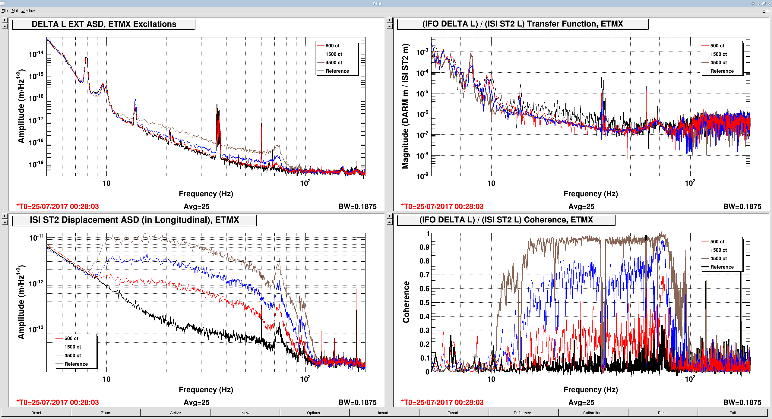
For each test mass: The DELTA L EXTERNAL spectra during excitations, along with calibrated displacement of each excitation, the resulting transfer function, and coherence.
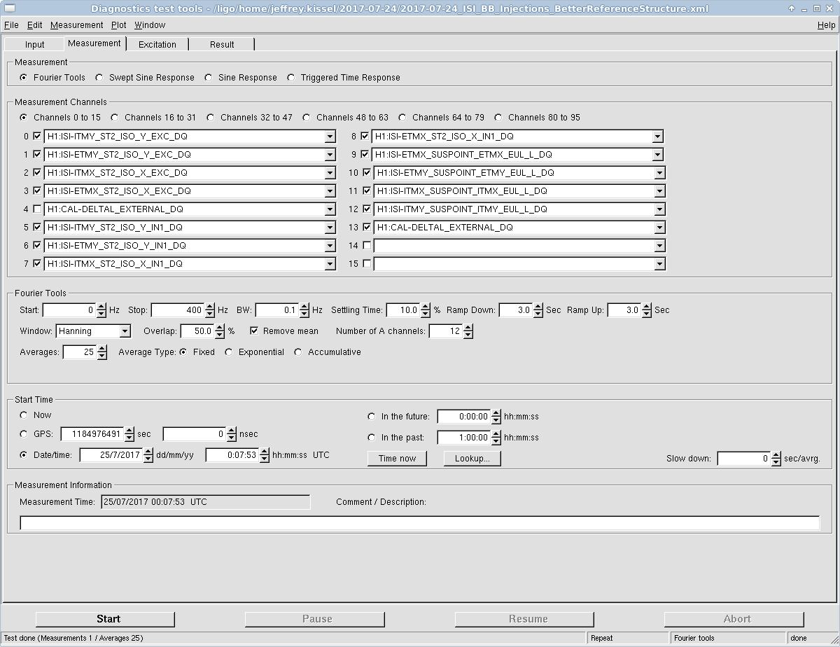
For those who may have to repeat the measurement, I attach screenshots of the DTT configuration and what channels I used explicitly. The template's too big to attach, but it lives in
/ligo/home/jeffrey.kissel/2017-07-242017-07-24_BSCISI_ST2_BB_Injections.xml
Also, shown for ETMX and ITMY, the projected ST2 Error Point both under excitation and during ambient conditions, with the residual transfer function shown below to expose how poor the calibration is.
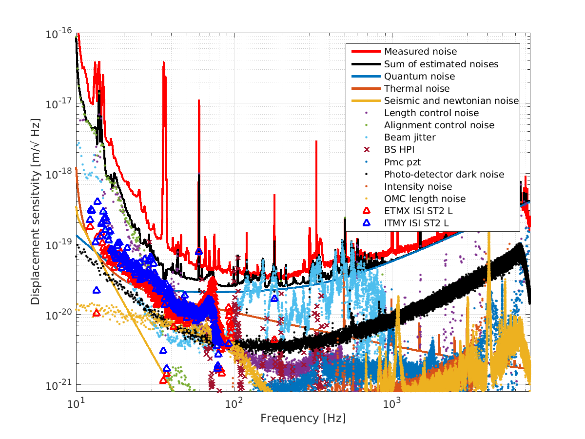
Jeff and I added his data to the simple noise budget. We are still using a pre-EQ darm noise in this plot, and you can see that the couplings he found explain some of our unexplained noise around 60-70 Hz.
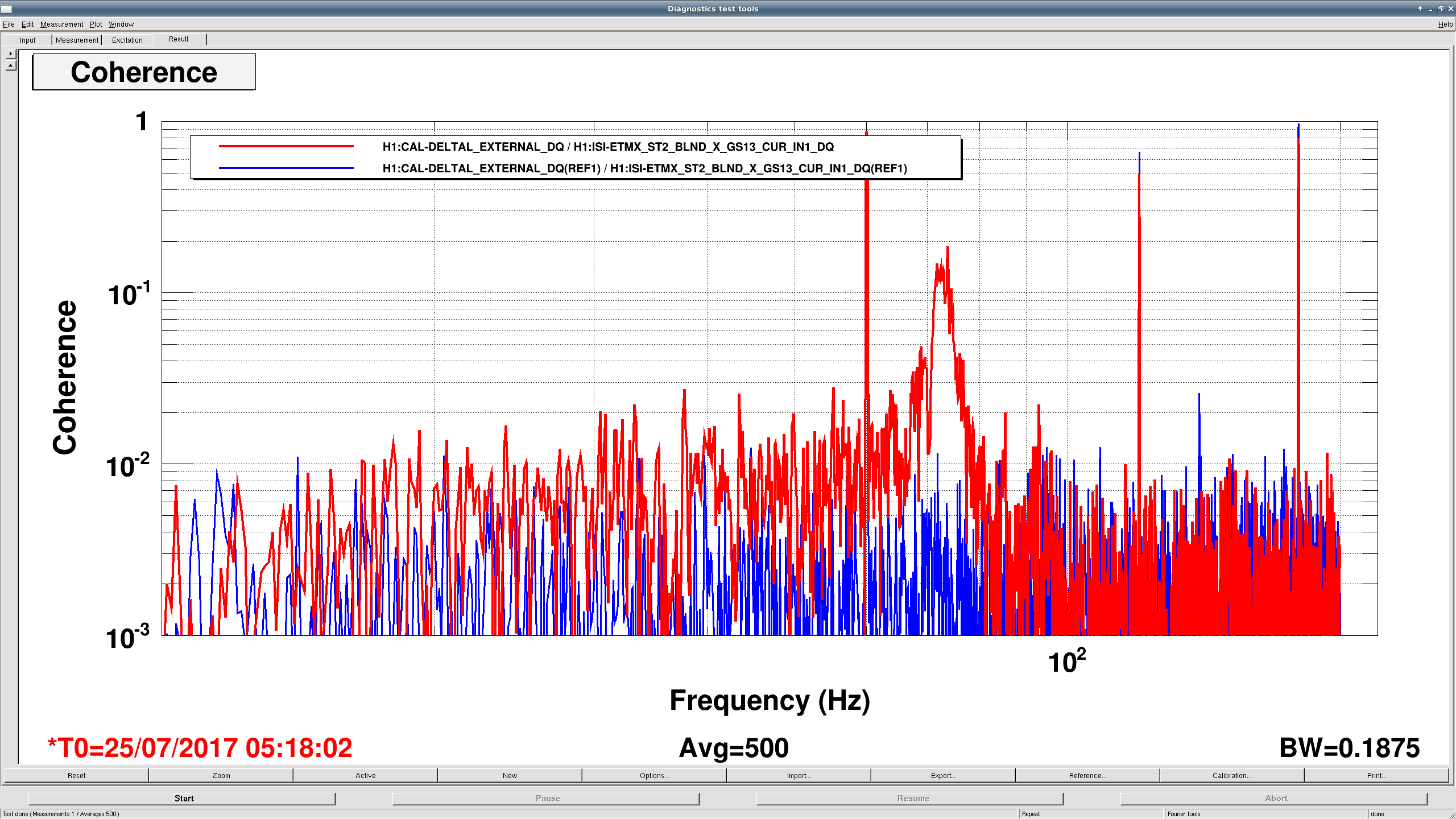
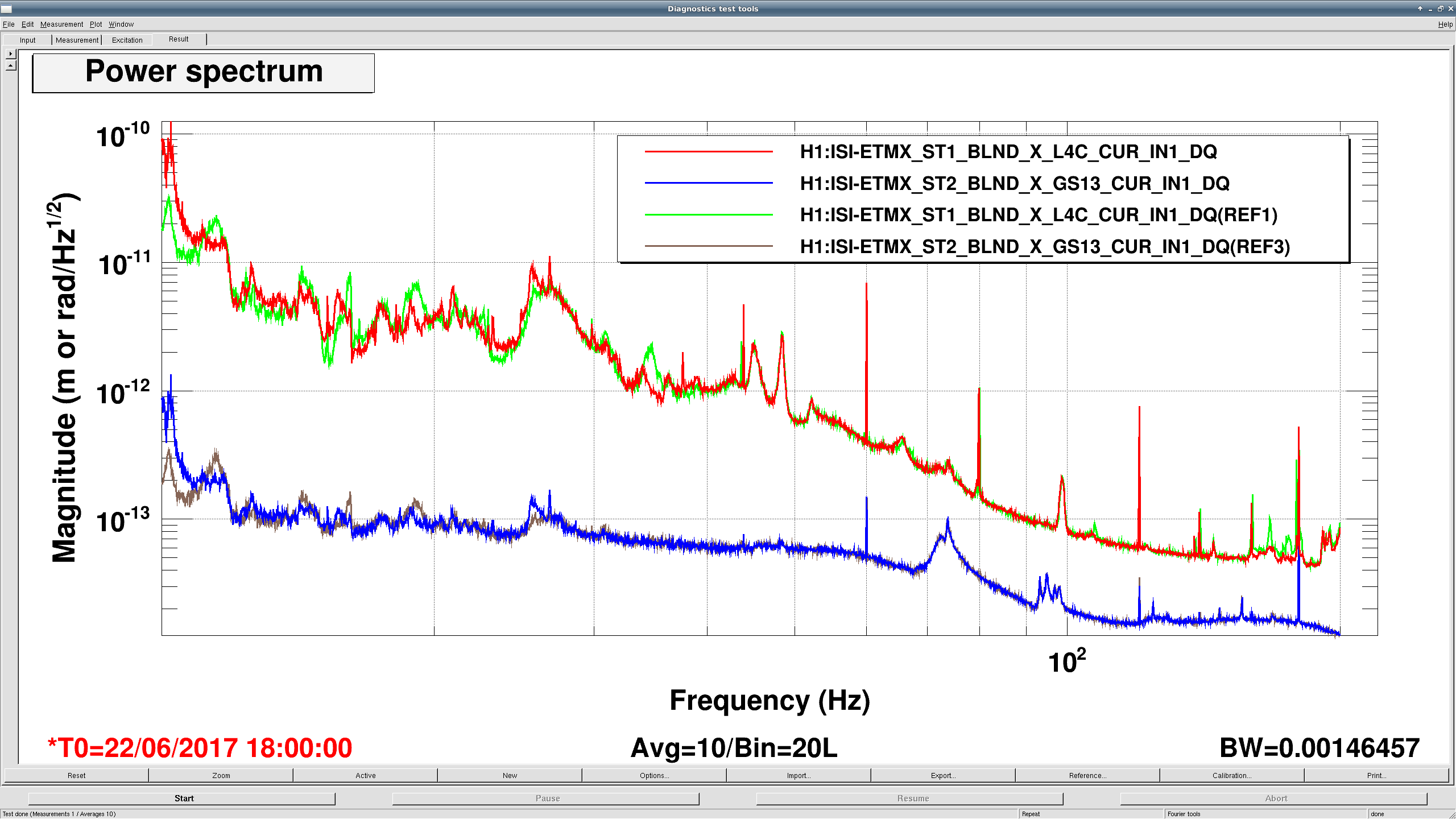
Adding a couple plots to show that ETMX ST2 coherence to CAL_DELTAL has changed, but measured motion doesn't seem to have changed. First plot is the coherence for 500 averages from the long lock on June 22, 2017 from 18:00 UTC on (in blue) to a similar window from the lock last night (red). The lump at 70-ish hz in red is new, not visible in the pink trace from June. Second plot shows the ST1 L4Cs and ST2 GS13s (both in meters) for the same periods (the June measurement is red and blue, last night are green and brown). The ST2 motion especially is nearly identical around the lump at 70 hz. Talking to Sheila, this maybe implies that scatter at EX is worse now than before.
I looked at all of the other BSCs as well for the lock segment last night, but none of the them showed the same coherence as ETMX.
For the record, here are two alogs from LLO on tests we've done:
BSC injections before O2 (when we found the problem with ITMY). We plan to repeat these before the end of the run.
O2 HAM injections (all clear to at least x10 above ambient).
If we are making a budget of the stage 2 motion to DARM then we should take into account the rotation motion also, since the bottom of the cage has ~2 meter lever arm
For off-site interested parties, I've committed the above template to the seismic repository here:
    /ligo/svncommon/SeiSVN/seismic/BSC-ISI/H1/Common/Data/2017-07-24_BSCISI_ST2_BB_Injections.xml
and corresponding key to all of the 100+ references in the template (as well as documentation of measurement times) is in the same location, with a similar name:
    /ligo/svncommon/SeiSVN/seismic/BSC-ISI/H1/Common/Data/2017-07-24_BSCISI_ST2_BB_Injections_ReferenceNotes.txt
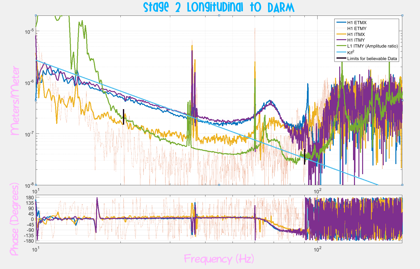
I've replotted some of Jeff's data for the stage to beam direction drive to Darm and added a plot from Ryan and Valera's (24820) similar data.
There are the four stage 2 motion to Darm transfer functions from H1 (I made the ETMY data dotted because it has no coherence)
There is a 1/f^2 line (light blue) which is what you might expect for the coupling from a charged path on the test mass to a moving charge (not quite a matching slope, but the transfer function phases all look like 0 degrees)
I wasn't able to recover transfer functions from the LLO data so I plotted the amplitude ratio for the one platform where there is excess signal in Darm (ITMY in green). The vertical black lines mark the limits of where there is excess signal and where you can believe that we have a decent estimate of the transfer function. The sensitivity on the other LLO chambers is much less (at least a factor of 5)
One more plug for a rotation measurement, a good measurement of the rotation to Darm transfer function on ETMX and/or ITMY would let us do some geometry to guess at the height of the coupling location (again assuming a point like integration between the cage and the suspension cage)