kyle.ryan@LIGO.ORG - posted 19:22, Tuesday 22 August 2017 - last comment - 10:09, Sunday 27 August 2017(38315)
TMDS training session at X-end
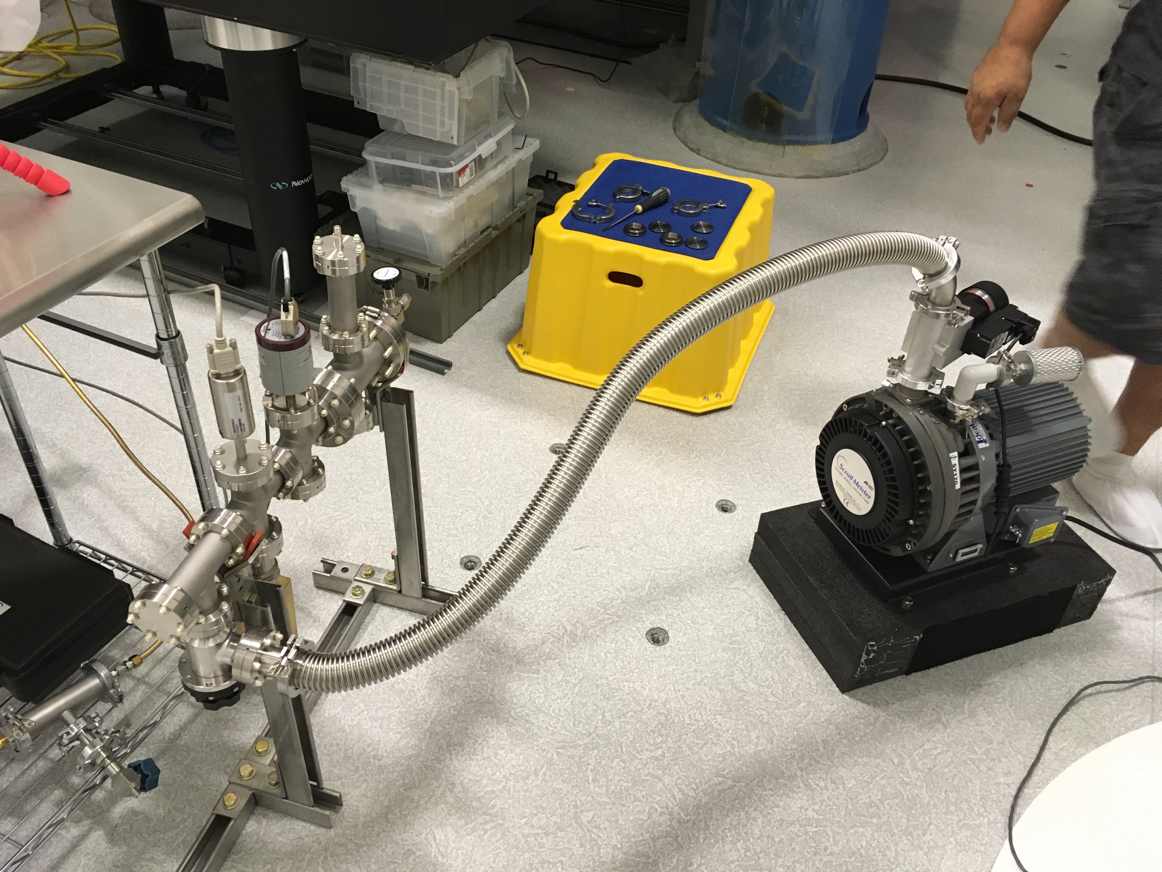
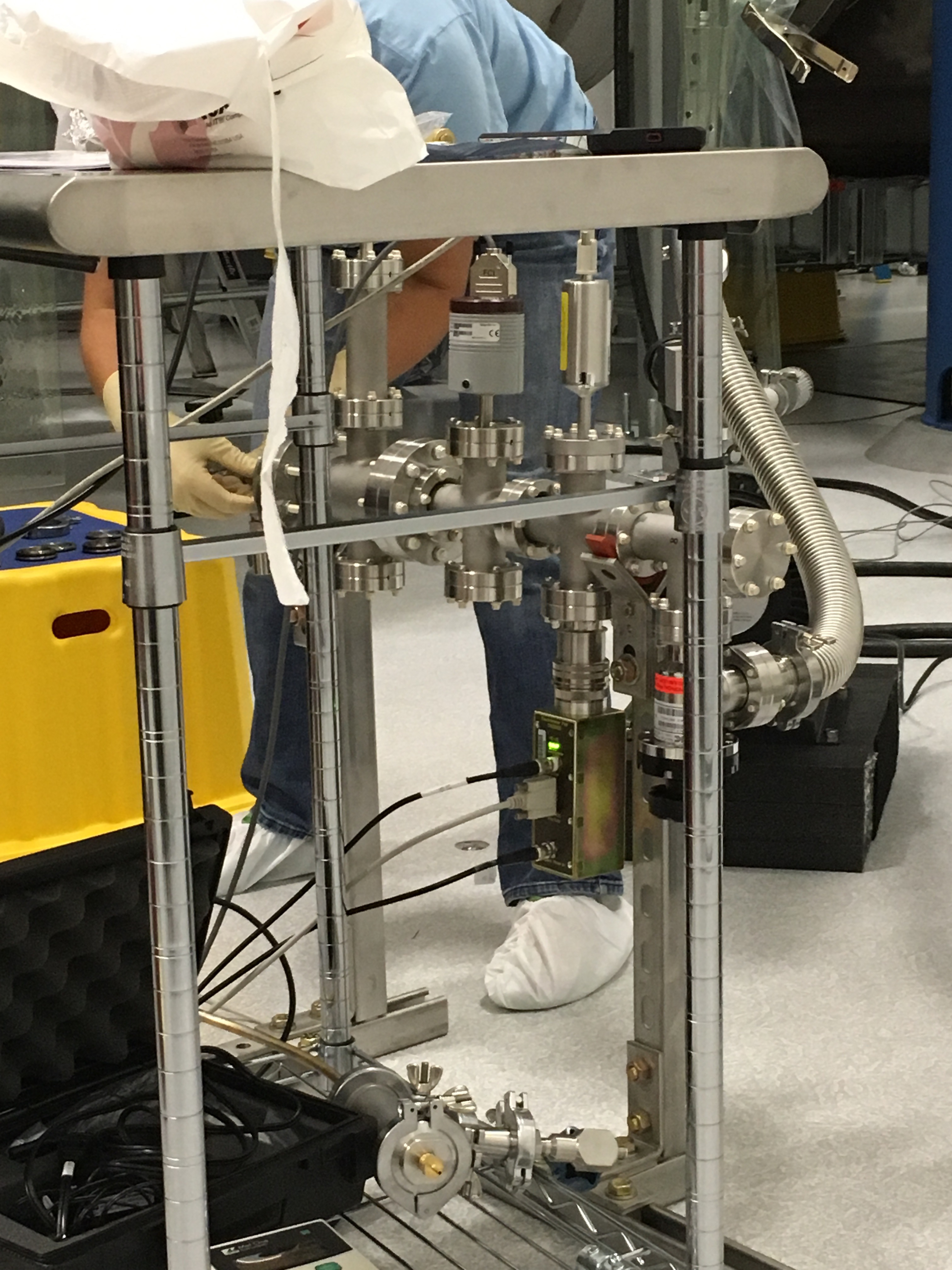
Rai W., Mike Z., Daniel S., Jeff K., Chandra R., Kyle R.

Today the TMDS Gas Delivery Table was transported to the X-end VEA and set it up for operation.  The actual Surface Discharge Ionizer was mounted on a stand for today's demonstration purposes.  Nominally, it would be mounted to the dedicated TMDS port of BSC9's East Door.  The Vent/Purge air supply was ran and dry air supplied to the TMDS setup.  Prior to exposing the Ionizer to the conditioned air supply, the plumbing connection at the Ionizer was decoupled and connected to a test setup that facilitated the measurement of > 0.3 micron and > 0.5 micron particulate in the conditioned air. The air line was then re-coupled to the Ionizer.  An approximate 50/50 mix of Ethylene Glycol to Alcohol along with "chunks" of dry ice was used as a cold trap to the path.

Rai W. gave an overview of the theory and a detailed tutorial as to the operation of the setup.  Daniel S. and Jeff K. noted details related to the ion production while Kyle R. and Chandra R. noted detail related to the vacuum related issues.

The Ionizer setup performed satisfactorily (with caveats) at making comparable amounts of positive and negative ions.

The plan now is to connect the Ionizer to BSC9 and perform an actual discharge of the ETMx during next Tuesday's maintenance day.

My notes from today;

1. Oscillations were noted and attributed to electronics design -> Daniel S. will address.
2. Rai W. requested that we provide a means of support to take the weight of the Ionizer when mounted to the 1 1/2" valve on the BSC -> Kyle R. will address.
3. Confirmation of the preferred means to pump to rough vacuum the X-end VE between cycles of discharge gas admission -> Chandra R. will address.
Non-image files attached to this report

Comments related to this report
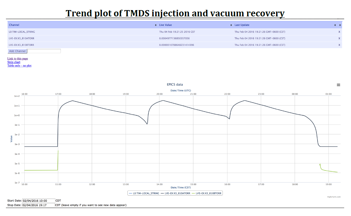
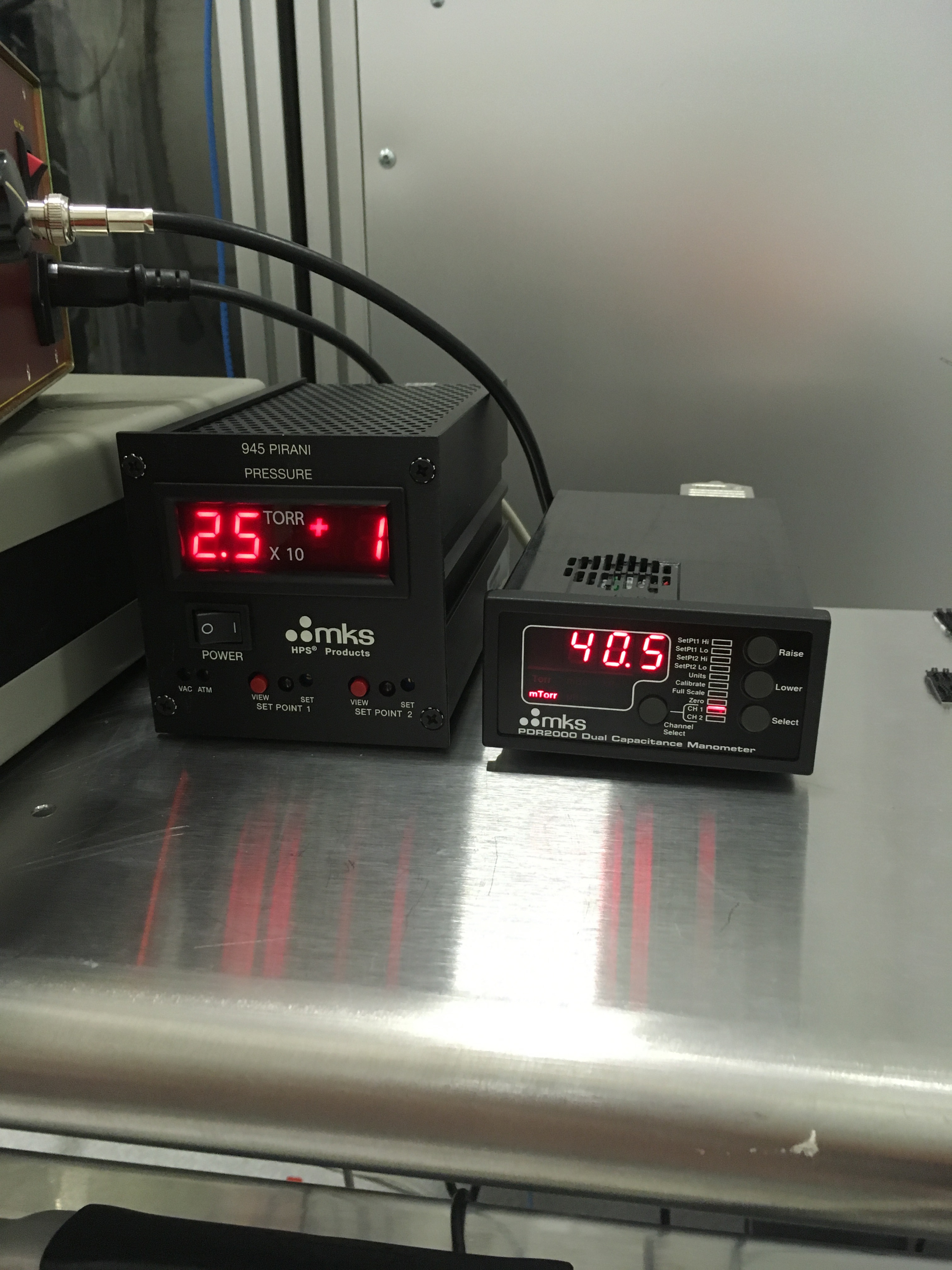
We will use the QDP80 to pump down the chamber between discharge cycles, with the turbo spun down and, as needed, use purge air to regulate the pump-side pressure to match the chamber pressure as to not break the 10" gate valve rated for 10 Torr differential pressure. Attached is a plot from LLO discharge. They spun up and down the turbo between cycles, but decided later it was not worth the trouble.
Images attached to this comment
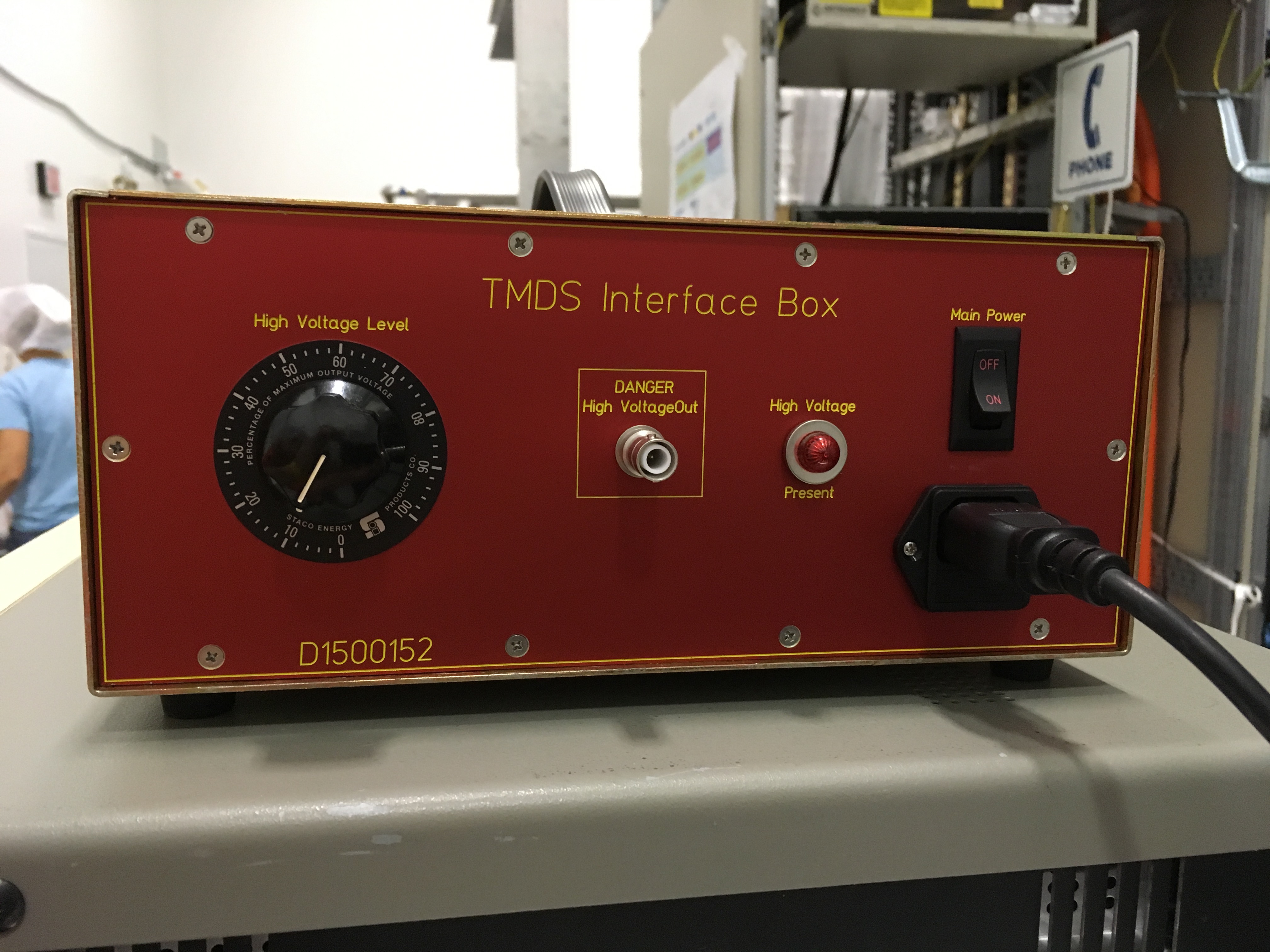
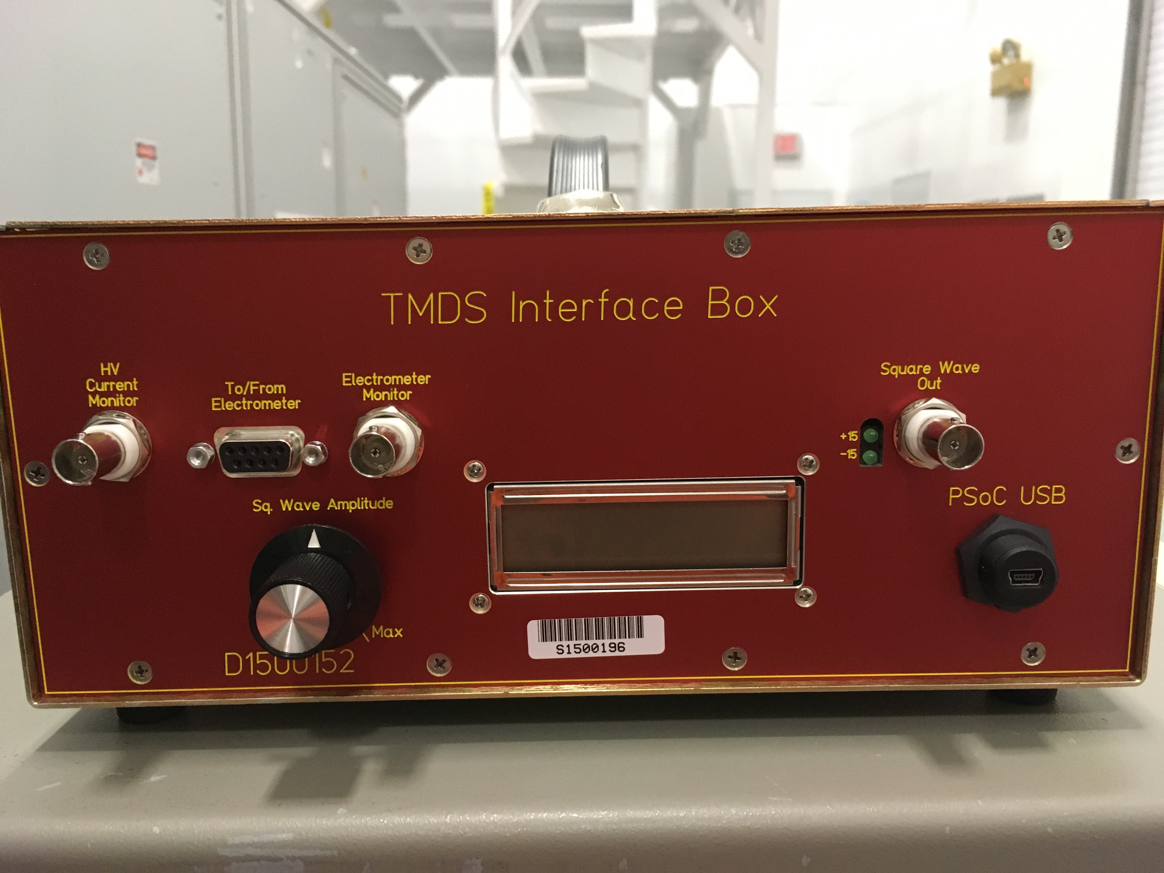
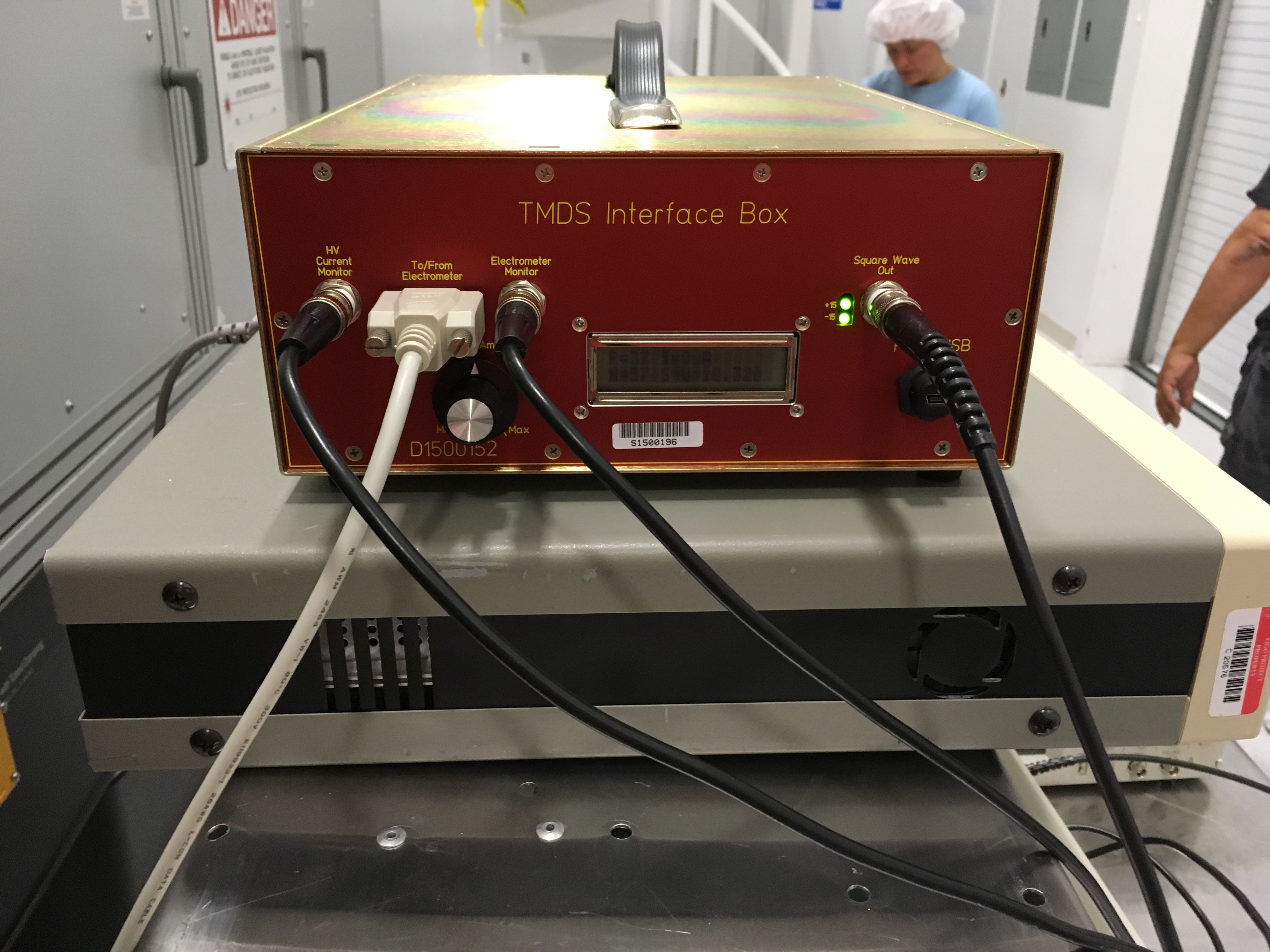
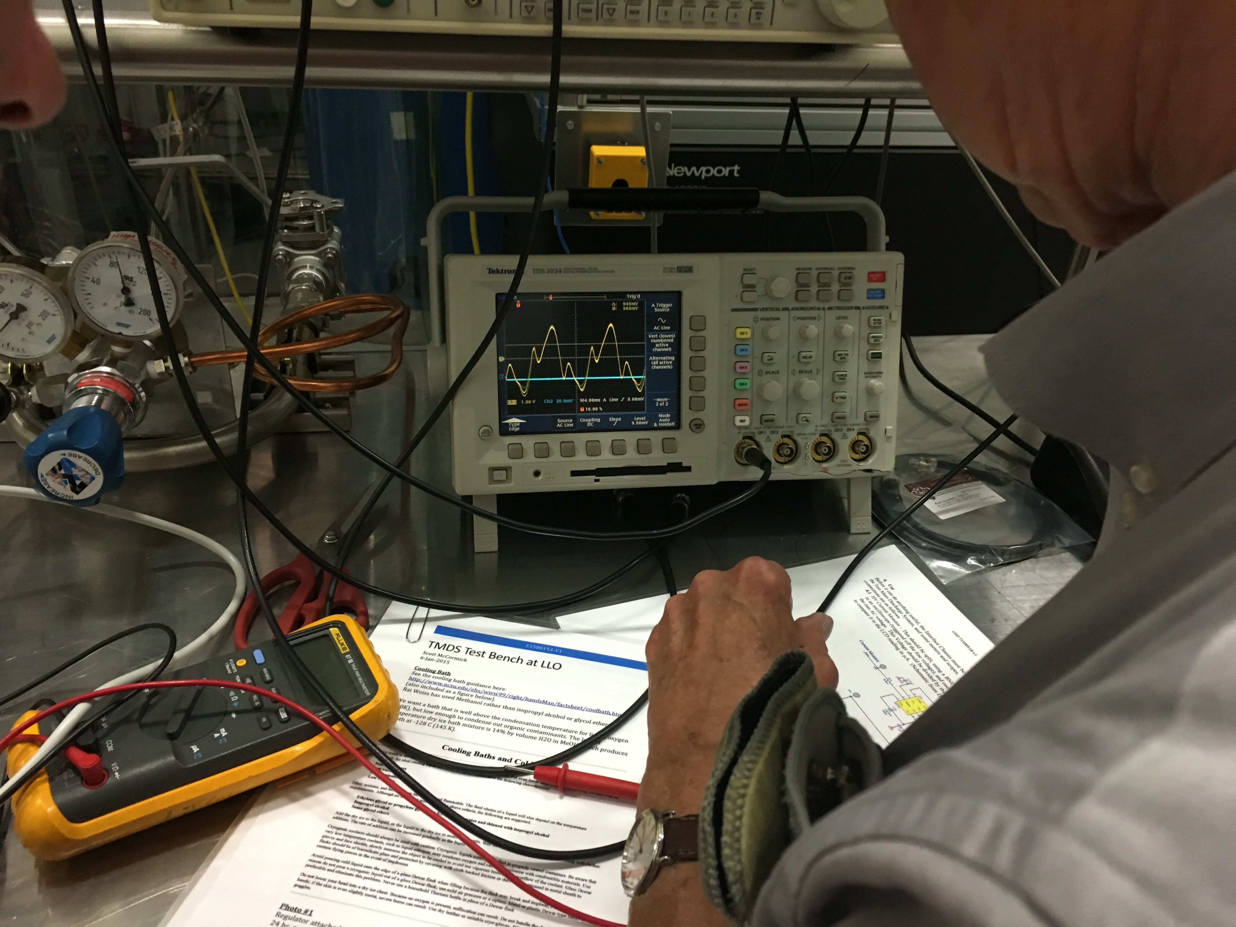
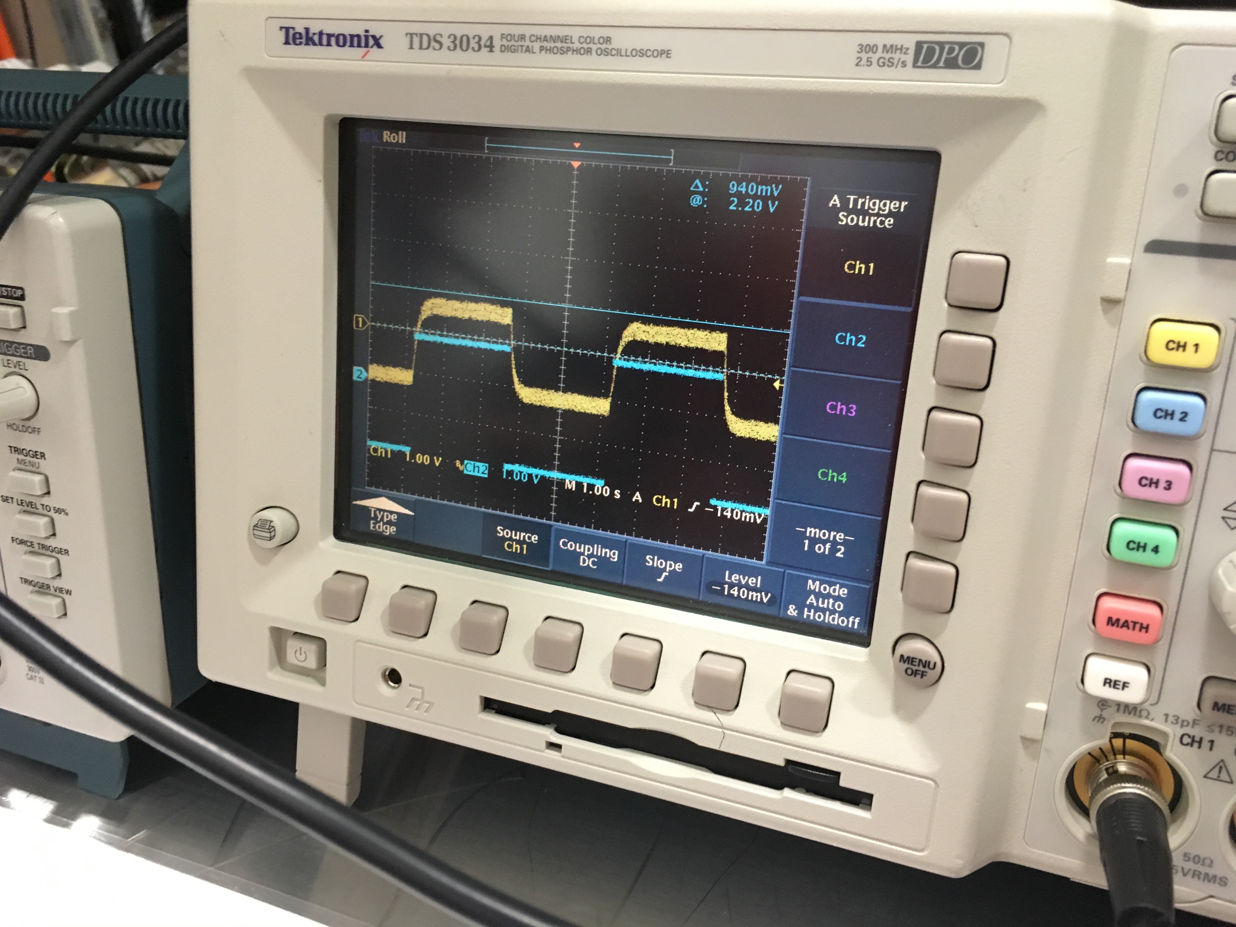
Refer to Figure 1 of T1400713, TMDS design document for elements of setup.

A couple of useful videos of the oscilloscope readouts during the experiment:

Lesson 1: Control and readback of the electrometer from the TMDS inferface chassis, D1500152.
    Rai has set up the readback of the electrometer with the square-wave input shown on the blue trace, and the electrometer readback in yellow. One is looking for an even balance in voltage from the positive and negative ions. The electrometer has a negative voltage bias at the time of recording, so it appears as though we're getting more positive than negative ions, but, rest assured, we're good.

Lesson 2: Demonstration of ionic discharge against TMDS chamber walls, if HV supply to ion generator is too high.
    The readback of the HV current is shown on the yellow trace. The video starts out with the ion generator discharging, as is evident by the rattiness of the waveform. At the last few seconds of the video, he reduces the VARIAC HV transformer gain, bringing the ion generator back to the desired level.

Lesson 3: Demonstration of electrometer readback once HV voltage is reduced
    Once the HV is tuned with the VARIAC, with the initial max amplitude of the square wave generator, then the square wave amplitude may be reduced to ~ 3 V pkpk (assuming a flow rate of about 30-50 [mL/s ?? not sure about those units]). Once we did this, we saw evidence for a ~3 MHz oscillation on the electrometer readback. Investigating the circuit drawing for the electrometer board (D1500061), Daniel and Mike agreed to replace the readback's output resistors R9 & R10 with ~100 [ohm] resistors.
This has been done already, and the electrometer has been reinstalled

Lesson 4: Final setup of readback / monitor system, in the "ready to discharge into chamber" configuration.
    Once again, Rai demonstrates the control of the HV VARIAC and the desire to keep the ion generator current readback from any rattiness in its waveform, which is indicative of ionic breakdown discharge against the TMDS chamber walls.

I attach a ton more pictures of the setup as well. Hopefully the filenames are a good enough caption.
Images attached to this comment
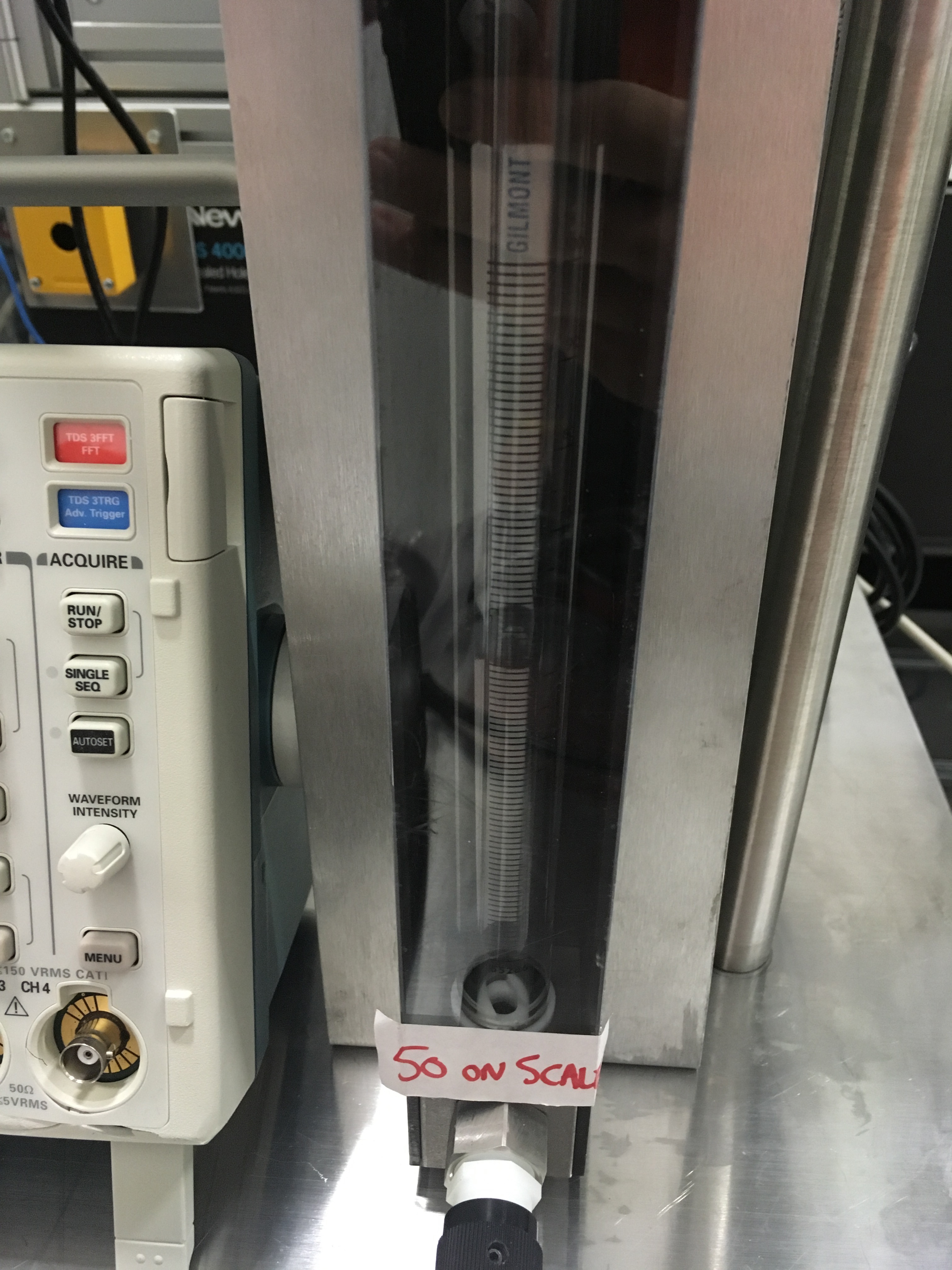
Desired gas flow rate 30 - 50 Liters per Minute (LPM)