J. Oberling, E. Merilh, P. King
A rather frustrating day with little progress. We started in the morning by turning down the diode current for the NPRO and the MOPA to get 35 W out of the MOPA. After trying several different settings, at Peter's suggestion we set the NPRO to output ~1.8 W; for this the diode current was set to 2.221 A, which yielded an output power of 1.81 W, which in turn gave 1.56 W at the entrance to the MOPA. Before adjusting the MOPA diode currents too much we wanted get a look at the beam profile, as adjusting the diode current by too much can change the beam profile (this is where things began to fall apart...). We intially set the WinCam behind the shutter for the 35W DBB path, as this was the only spot with enough room for the WinCam; the MOPA diode currents were set at 44.0 A for D1 and D2, and 45.0 for D3 and D4 (a leftover from earlier adjustments). The beam profile here looked horrendous. It was at least round, but there was a significant shoulder that ringed the bottom half of the beam; changing the MOPA diode currents up and down only served to make the profile worse. Seeing this, we decided to go ahead and skip the MOPA diode current adjustment (leaving the currents at the previously stated level) and move straight into mode matching.
From section 4.3.4 of the 35W FE laser user manual (T0900646), the MOPA wants a 150 µm diameter beam approximately 30 mm inside the MOPA enclosure. Using the leakage beam on mirror FE_M4, we measured out the required distance and set up the WinCam. The beam diameter at this point was ~330 µm horizontal and ~377 µm vertical. We then proceeded to adjust the mode matching lenses to improve this. We moved lens FE_L3 towards the NPRO by a few cm (had to loosen the pedestal the lens was attached to in order to make the move) and lens FE_L4 towards the NPRO by ~4 mm. This gave us a beam diameter of ~290 µm horizontal and ~310 µm vertical; still not where it should be, but better than it was. We then installed the 200W power meter at the exit of the FE and turned on the MOPA. At the same pump diode currents (44.0 and 45.0 A respectively), the laser was outputting 28.5 W. Ed tweaked the beam alignment into the MOPA and we ended up with 36.0 W output from the FE. Unfortunately, the beam profile was unchanged (I did not have the presence of mind to get a picture of the beam here).
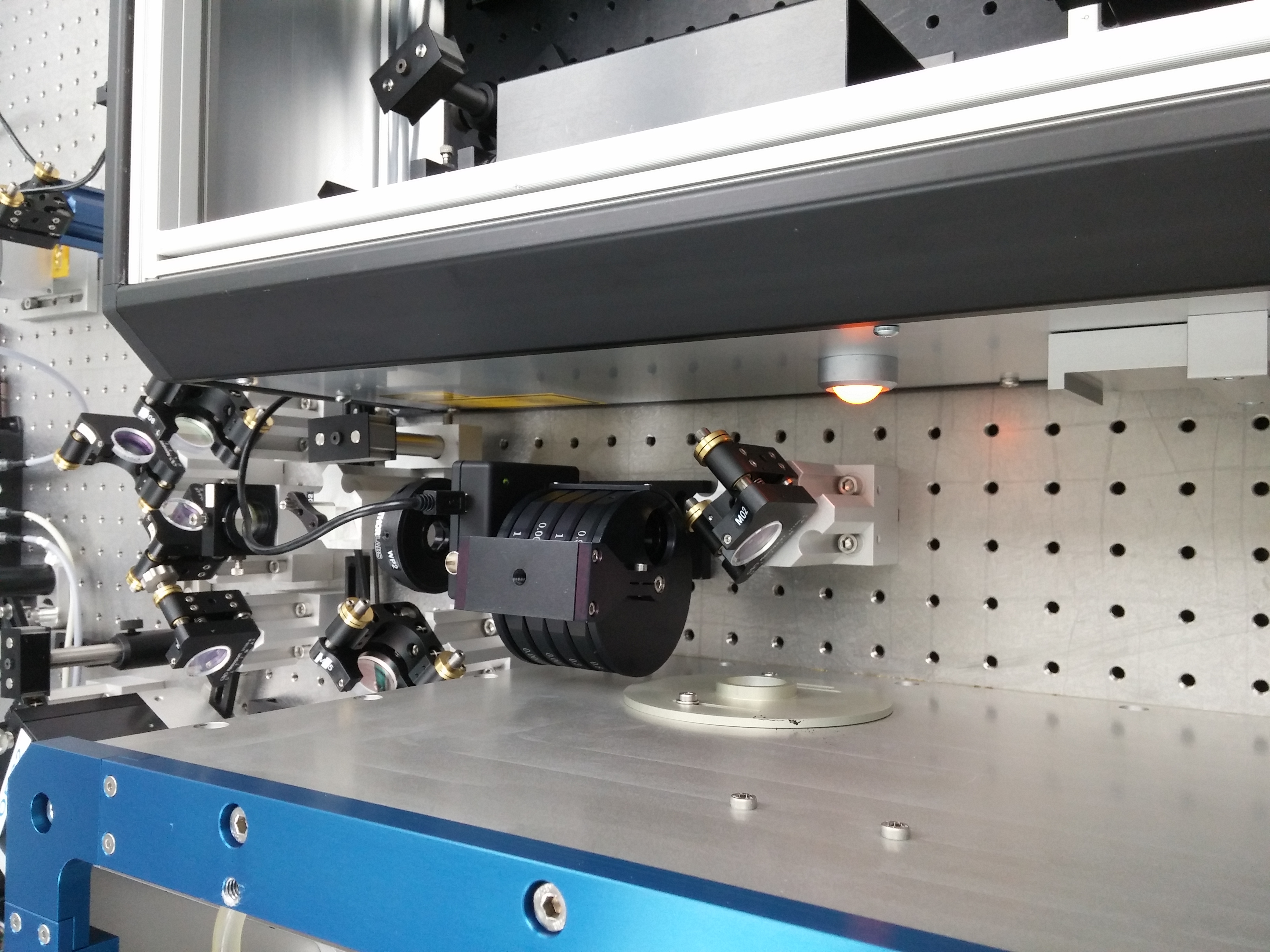
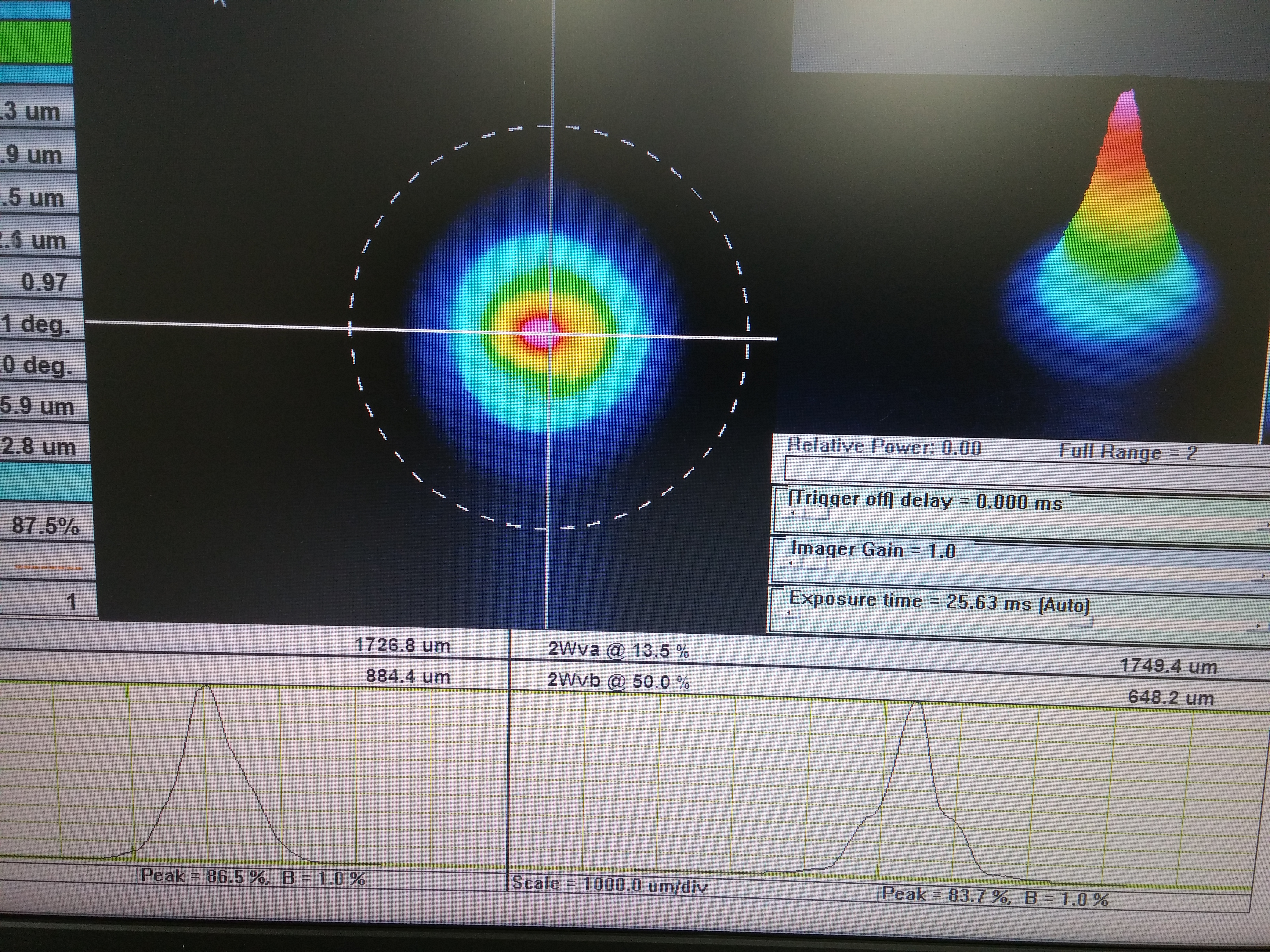
Thinking that maybe we were clipping on something, we checked the FE alignment through the HPO irises to get an idea of how misaligned the beam was. These actually looked pretty good; horizontal alignment through the irises was as before the swap, vertical alignment was slightly high. Peter was thinking that there could be something in the optical path from the FE to the WinCam down the DBB path that could be contributing to the beam profile issue (some back reflection causing interference maybe?). To check this, the polarizing beam splitter cube PBS01 was removed from the table and the WinCam was installed in its place (this is the pick-off right behind the turning mirror M02 that directs the FE beam into the HPO, see first attachment); in this way we eliminated the entirety of the DBB path. At this point in the optical path the beam looked much better, round and almost Gaussian. I tweaked the horizontal alignment into the MOPA to get the beam symmetric, the results are shown in the 2nd attachment (beam profile is rotated by +90°, i.e. UP is on the right side of the profile). At this point we called it a night and will continue mode matching and HPO recovery on Monday.