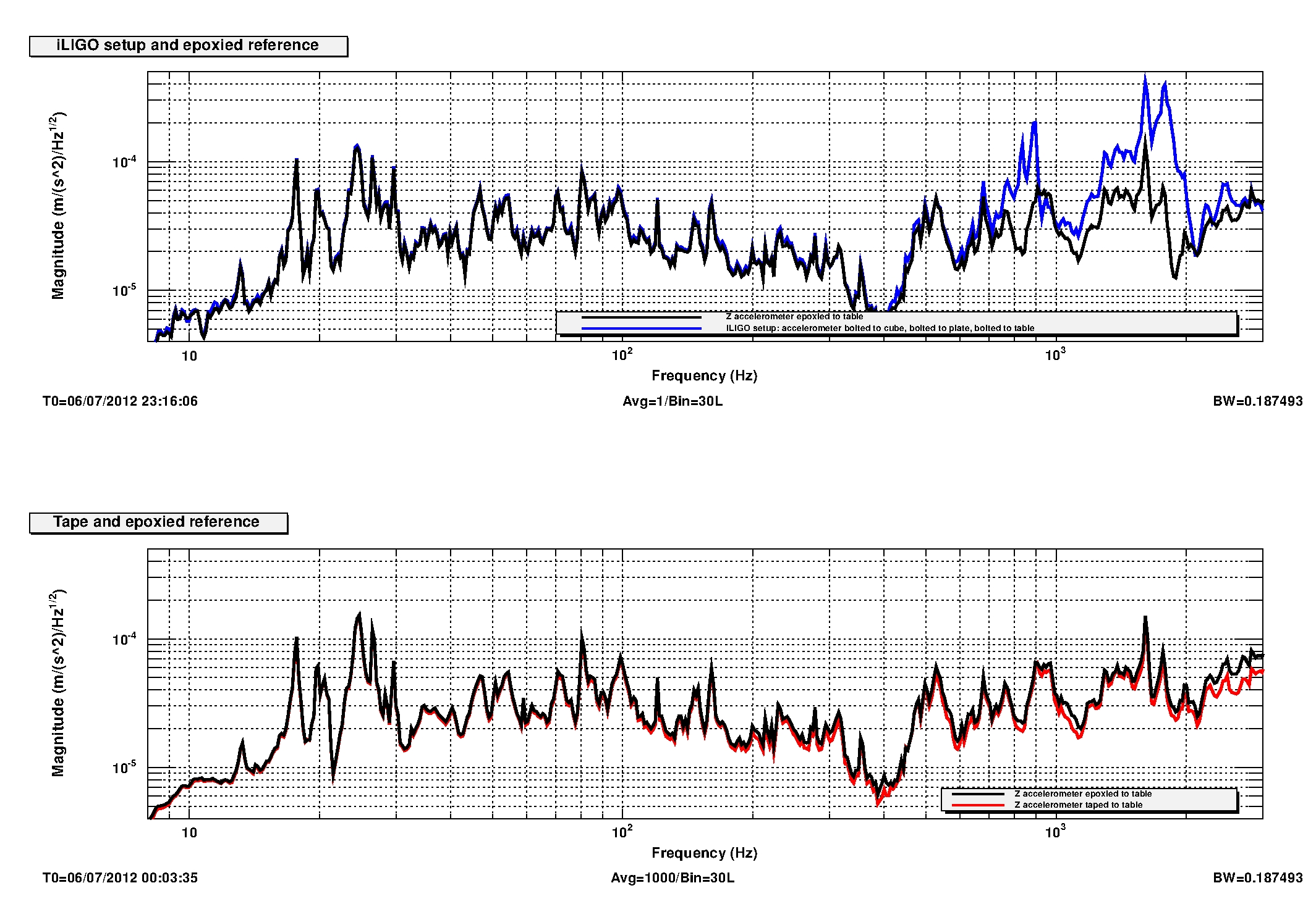
During iLIGO, there were 3-axis accelerometers that were mounted on the tabletops of optics tables. This was done by bolting three accelerometers to the sides of a aluminum cube that was then bolted down to a aluminum plate, which was bolted to the table. This mounting scheme, however, introduced a ~900Hz signal, associated with the resonance of the cube and the plate, into the accelerometer channels. We investigated new mounting schemes to use during aLIGO, and compared them.
For all the tests, we used as our reference an accelerometer that was attached to the table surface with a thin layer epoxy. The hole at the bottom of the accelerometer normally used for bolting it to cubes was sealed with a set screw to avoid having epoxy seep between the threads. The epoxy was Devcon 5-minute epoxy, which was applied to the bottom of the accelerometer. Excess epoxy was scraped off using the flat side of the mixing stick, to have the layer be as thin as we could make it. The accelerometer was then placed on the table, in an area where it was not over any of the holes for bolts, and the epoxy was allowed to cure for 5 minutes before the cable was attached to it. The thickness of such a layer of epoxy is no more than 0.3mm.
---------------------
SUCCESSFUL MOUNTINGS:
Items Used:
- Wilcoxon accelerometer, model 731-207
- Wilcoxon 1in. triaxial aluminum mounting cube, model TC1
- 520 ft Thermax RGS-316 cable
Z-axis mounting:
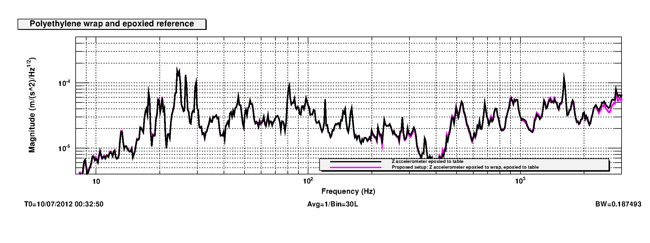
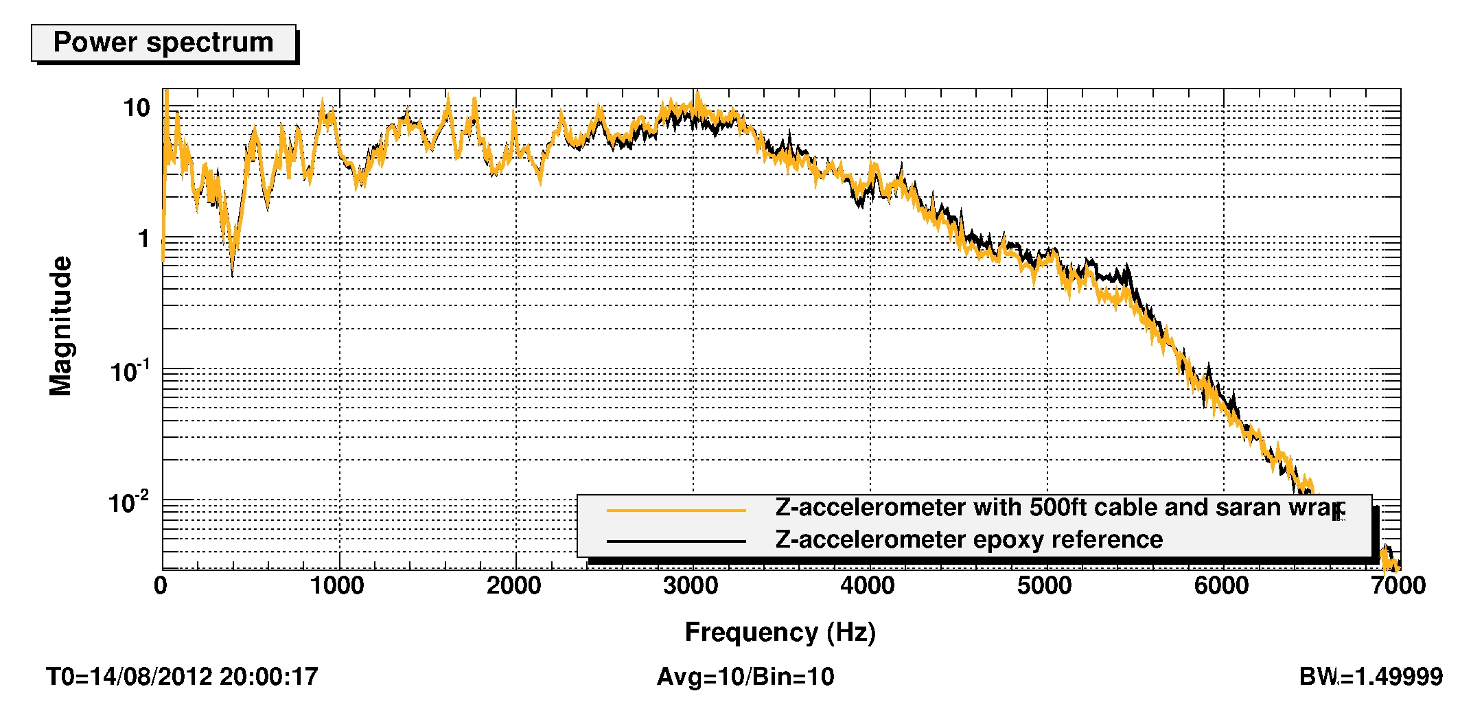
We tried adding a layer of Glad polyethylene wrap between the accelerometer and the table. A thin layer of epoxy was first applied to the accelerometer, and a piece of wrap was pulled taut against the bottom of the accelerometer. Then another thin layer of epoxy was applied to the wrap, and then the accelerometer was pressed to the table. The purpose of adding the layer of polyethylene wrap is to isolate the accelerometer from the object it's mounted to, since a thin layer of epoxy may actually allow parts of the metal exterior of the accelerometer to come into contact with the table. The combination of the epoxy and polyethylene wrap added 0.3mm to the heght of the accelerometer (the wrap itself is ~0.5 mils thick). We found that adding this layer does not make the signal deviate too much from that of the reference (see attachment 1).
Triple-axis mounting:
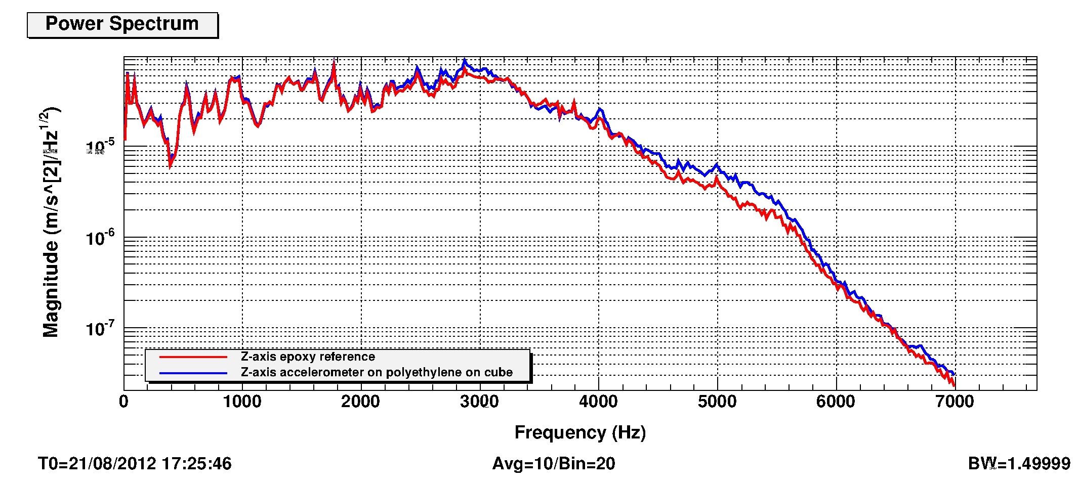
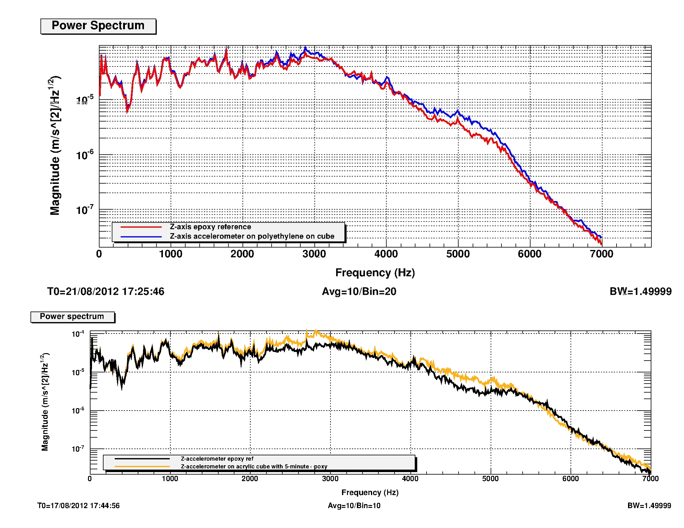
We tried attaching an accelerometer with a layer of polyethylene wrap on the bottom (as above) to an aluminum cube using epoxy, and attaching that cube to the table using epoxy. This also does not make the accelerometer signal deviate significantly from that of the reference (see attachment 2). For actual installation of triple-axis accelerometers, we recommend first attaching three accelerometers to a metal cube using the epoxy-polyethylene-epoxy method described above, outside the LVEA. Once the epoxy has cured and the triple-axis setup is stable, one only needs to use one batch of epoxy near the table to mount the cube. We tested a similar setup but with a (non-conductive) acrylic cube instead, but found that the aluminum cubes give better performance (see attachment 3).
Temporary mounting:
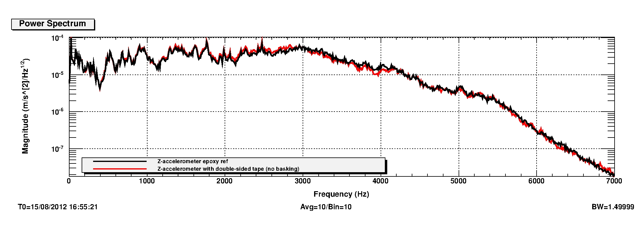
For temporary installations, we tested 1in wide double-sided clear clean room tape. Previously, in iLIGO, double-sided Scotch tape was used, but for aLIGO we wish to use particle-free adhesives such as clean room tape. We found that this mounting allowed the accelerometer to respond to vibrations in a similar way to the epoxied reference (see attachment 4). There were two kinds of clean room tape we tried, one that had a peel-away backing, and one that did not. Since the backing is a hassle to peel off, the tape without the backing is preferred.
Extra long cables:
For cases where extra long cables need to be used for an accelerometer, we verified that the length of the cable does not affect the accelerometer readings. We tested a 520 ft Thermax RGS-316 cable with an accelerometer that was epoxied to the table, next to the reference, and found no effects from using a longer cable (see attachment 5).
---------------------
SUB-OPTIMAL MOUNTINGS:
The first mounting scheme we tested was double-sided tape, used in temporary setups during iLIGO. This kind of mounting is useful in temporary installations, not specific to optics tables. The tape used was Scotch Permanent Double Sided Tape, 0.5in wide. Two parallel, non-overlapping strips were placed across the bottom of the accelerometer, which is 1in in diameter, and the accelerometer was pressed to the table surface, again away from any holes. It was placed adjacent to the reference to avoid variations due to positioning on the table. The tape was also found to be non-conductive, so it isolates the accelerometer from the object it's mounted to. We found that when taped to the table, the accelerometer behaves very similarly to one that is epoxied to the table (see attachment 6). However due to cleanliness concerns we opted to use clean room tape for future installations.
Next we compared the iLIGO setup to the epoxied reference. We again found the 900Hz resonance of the cube and plate entering the accelerometer channel (see attachment 6).
Other methods we tried were:
-
Accelerometer bolted to aluminum cube bolted to brown plastic plate (one of the iLIGO setups)
-
Accelerometer resting on the table (no mount)
-
Accelerometer bolted to cube taped to table
-
Accelerometer bolted to cube epoxied to table
-
Accelerometer taped to cube epoxied to table
-
Accelerometer epoxied to cube dog clamped to table
-
+ polyethylene wrap between cube and table
-
+ foam stuffed in dog clamp slot
-
+ foam between dog clamp and cube
-
-
+ different position on the table
-
+ cube replacement
-
+ tightening of the clamp
-
+ maximum tightening of the clamp
-
-
+ foil between clamp and cube
-
+ foil between cube and table
-
+ foil above and below cube
-
-
Accelerometer with a thin layer of epoxy + polyethylene wrap + a thick layer (0.7-1.0mm) of epoxy to the table
-
Accelerometer epoxied to cube bolted to plate
-
+ foil between cube and plate
-
+ foil between plate and table
-
+ foil above and below plate
-
Maggie Tse, Robert Schofield