1. Betsy and Travis scrutinized the beam position on SRM and SR2.
After they're done, to me the beam position on the back baffle hole of SRM seems to have moved further to -X direction by a mm or two but the beam was moving and we weren't sure.
2. At this point the rejected beam from OFI cleared the rotator.
Good.
The beam cleared the OFI rotator and was going to the direction of ZM2. The beam spot on two steering mirrors on OFI were to the +X direction. Since Koji didn't want to move the mirror base plate position while he was here, we only turned the mirror holder to center the beam on the second mirror (the first mirror is still off centered but it's far enough from the edge).
TJ installed the ZM2 on the new riser and put it roughly at where it should be, so we aligned the second steering mirror on the OFI to roughly center the beam on ZM2. TJ also installed the beam dump with the right post.
Gerardo needs to confirm the OFI alignment relative to the beam again.
3. Septum window was rotated 180 degrees.
The scribe mark showing the thickest side is now at 9 o'clock position (i.e. +X).
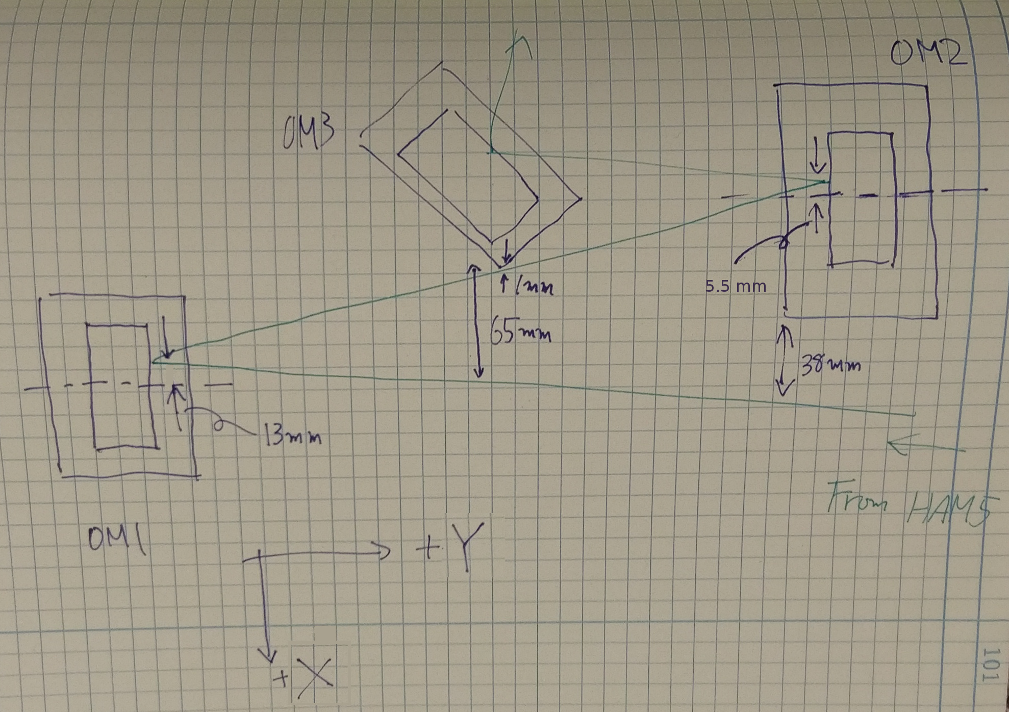
Yesterday the beam was at X=-36mm on OM1, I expected that the septum rotation will bring the beam to -9mm position (alog 39491). In reality the beam was at -13mm position. At least the movement in the correct direction, height is still correct.
Without doing anything, the beam was already hitting OM2 though too low. Attached shows some measurement numbers we made.
4. What needs to be done for HAM6.
VOPO path:
This needs to be done before corner pump down. Irises need to be installed. ZM2 and OFI steering mirror on HAM5 needs to be adjusted to center the rejected beam on irises on HAM6.
In principle the following could be done after the corner pump down with the IMC locked, but we should convince ourselves that this will absolutely work.
OMC path:
To make sure that no part of the beam comes too close to any of the edges, unfortunately OM2 needs to be moved to +X direction, meaning OM3 needs to be rotated.
OM1 is pushed to -X by 13mm, rotated to send the beam to the center of new OM2 location (and rebalanced as the beam is too low on OM2).
OM2 is pushed to +X by 19mm or so, this will increase the distance between the OM1-OM2 line and the edge of the OM3 by 10mm-ish. OM2 also needs to be rebalanced as the angle of the beam coming from OM1 will be different.
OM3 is rotated to accommodate the beam angle change.
I and Sheila convinced ourselves that this will work though painful.
ASC-AS_C path:
Everything could be moved to -X by 13mm or so and it will be fine.
I and Sheila convinced ourselves that this will work.
OMC REFL path:
Beam diverter will be reused for SQZ path, OMC REFL QPD sled wasn't used and probably will not be used, so most of this path could be replaced by a single high power beam dump?
OMC TRANS path:
No need to do anything?