jeffrey.kissel@LIGO.ORG - posted 17:34, Monday 18 December 2017 - last comment - 11:34, Wednesday 20 December 2017(39804)
Finalized ISS Array Input, IM4 Trans QPD, External MC REFL and Trans Viewport Beam Alignment
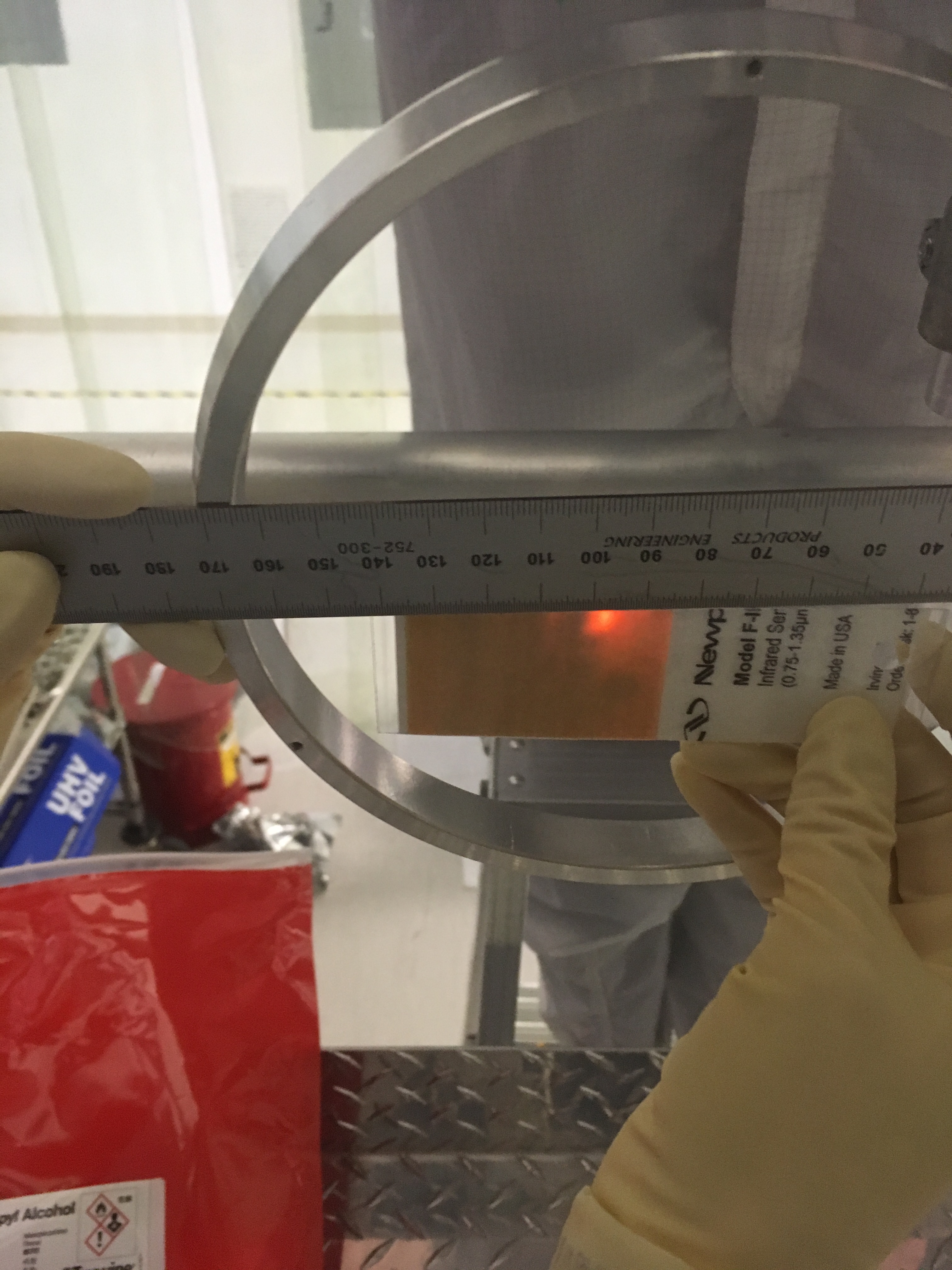
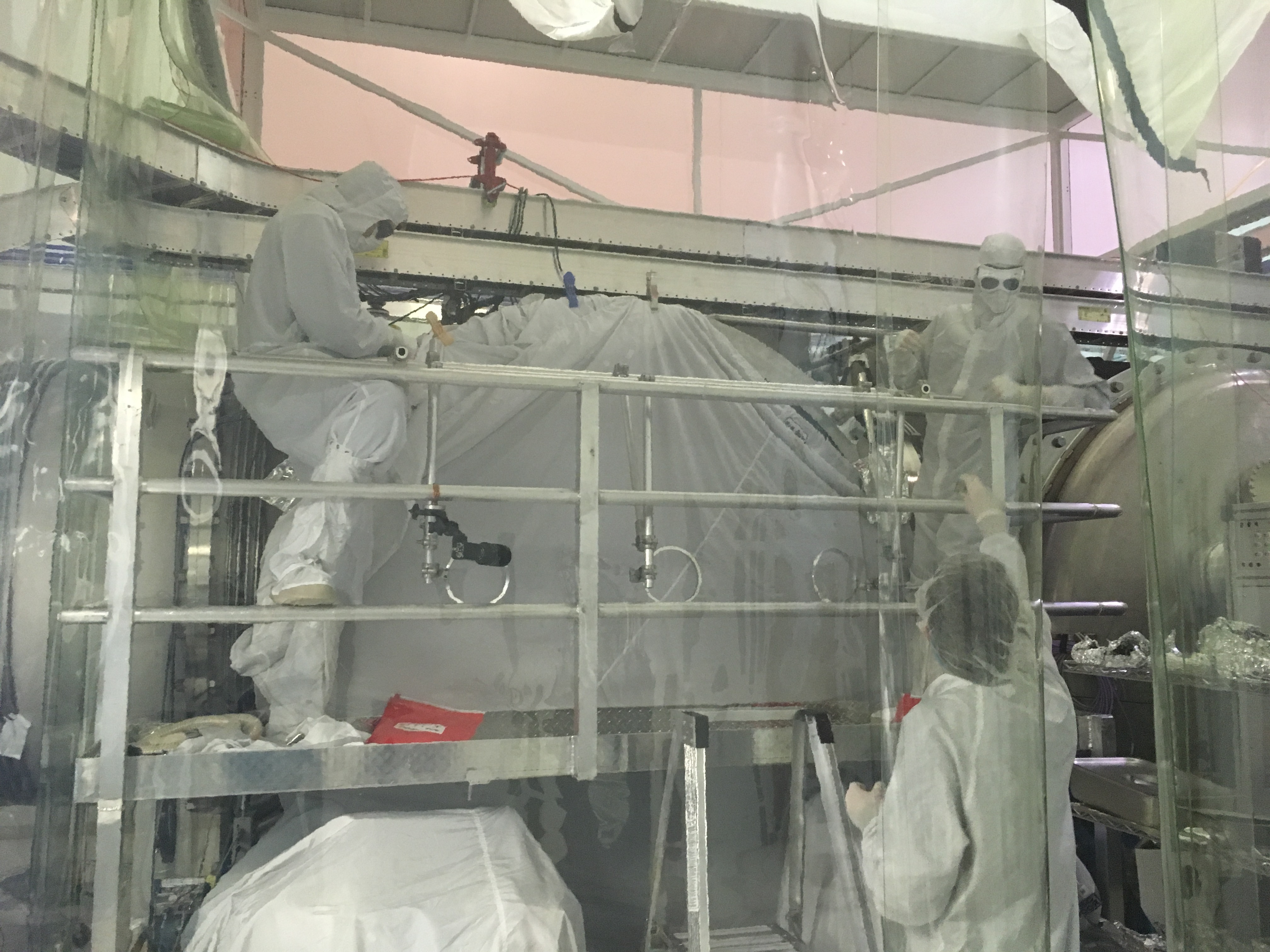
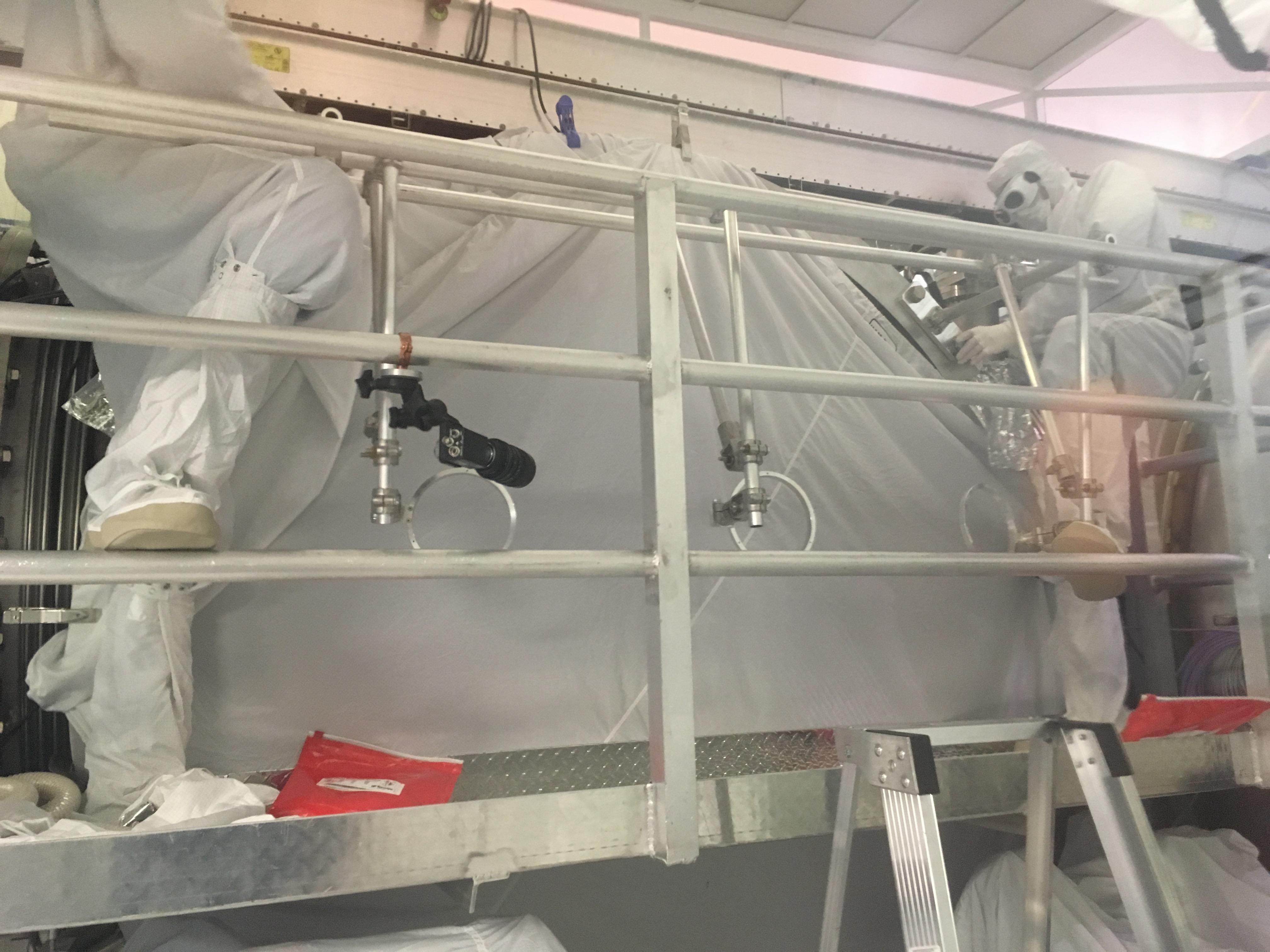
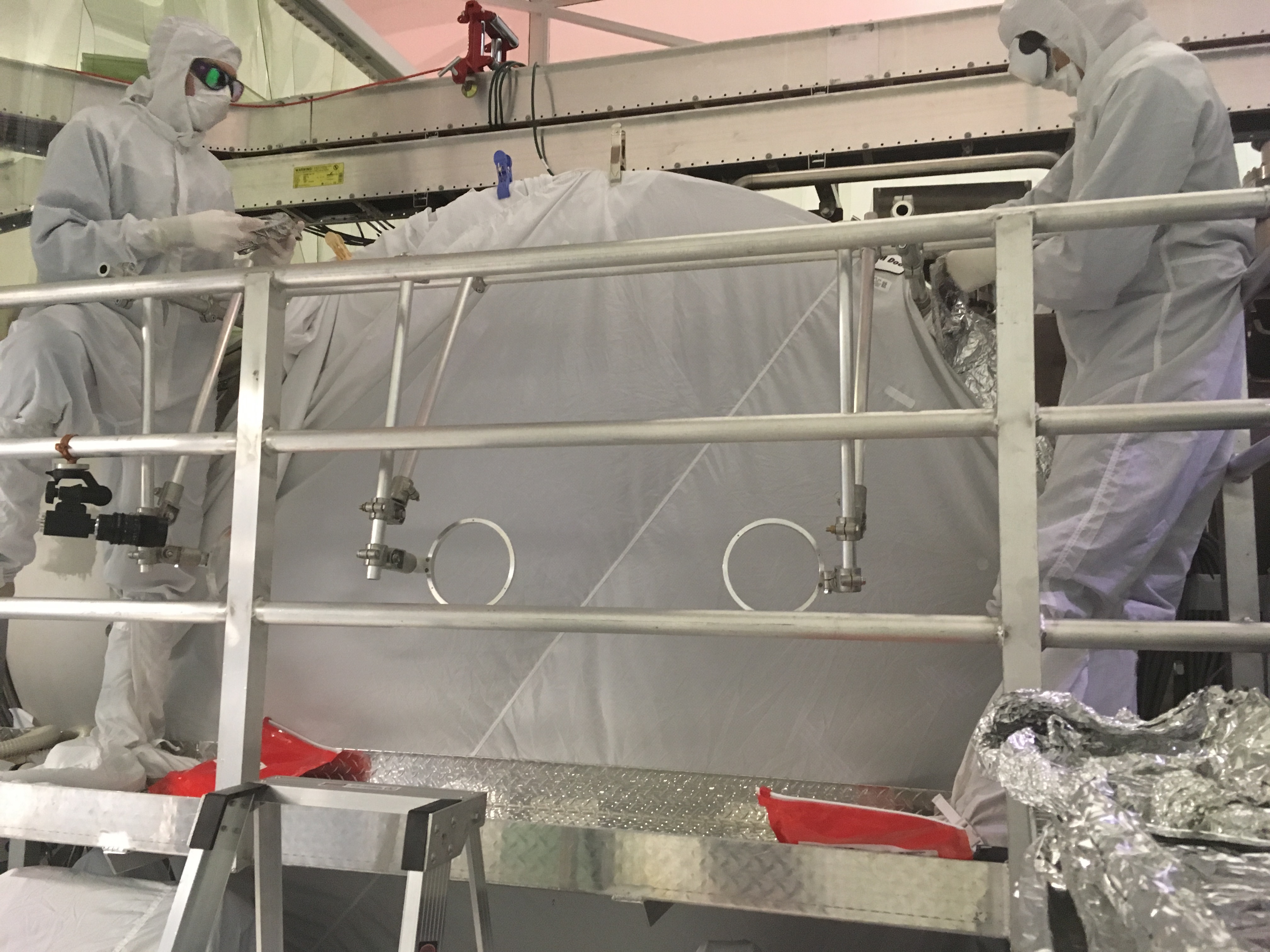
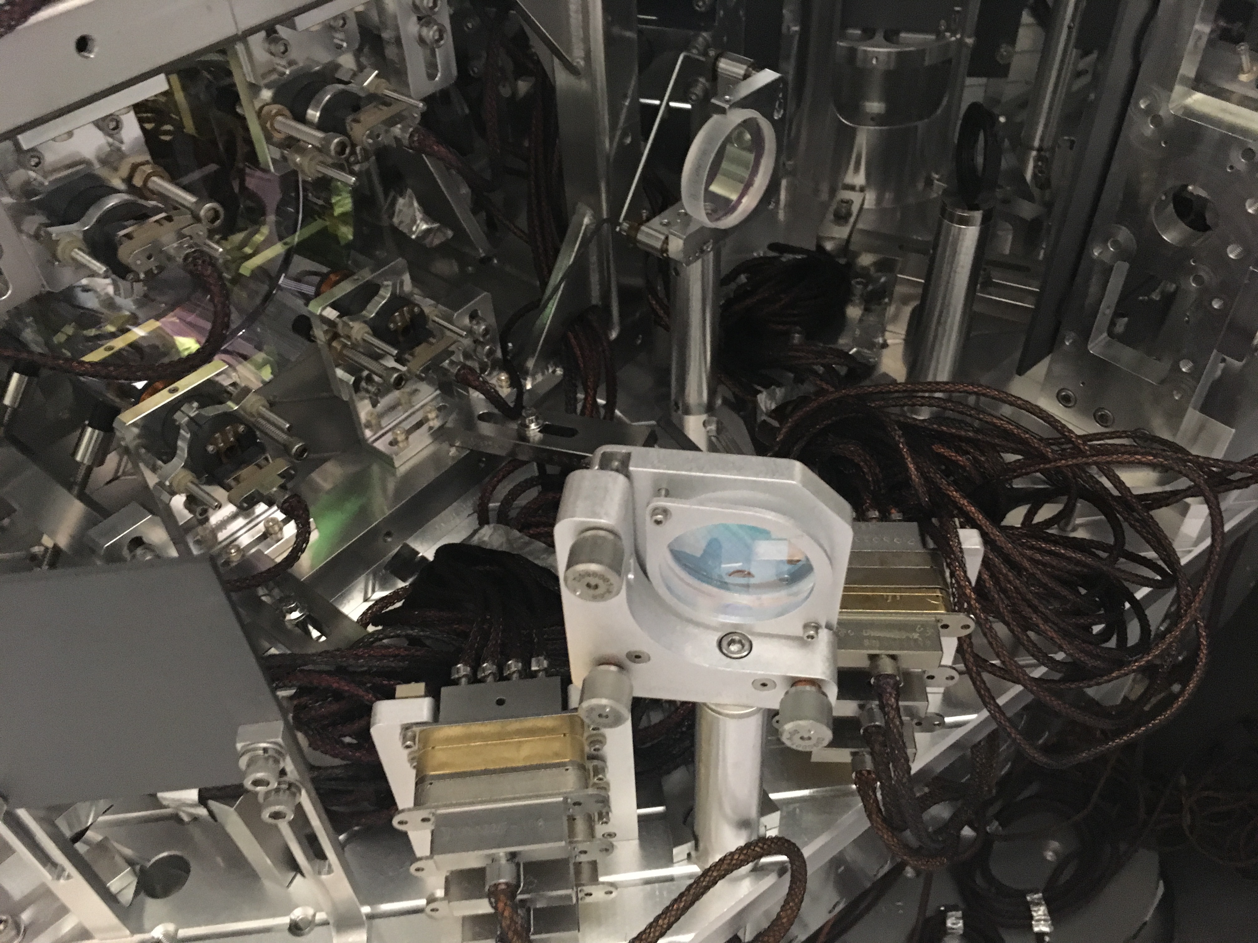
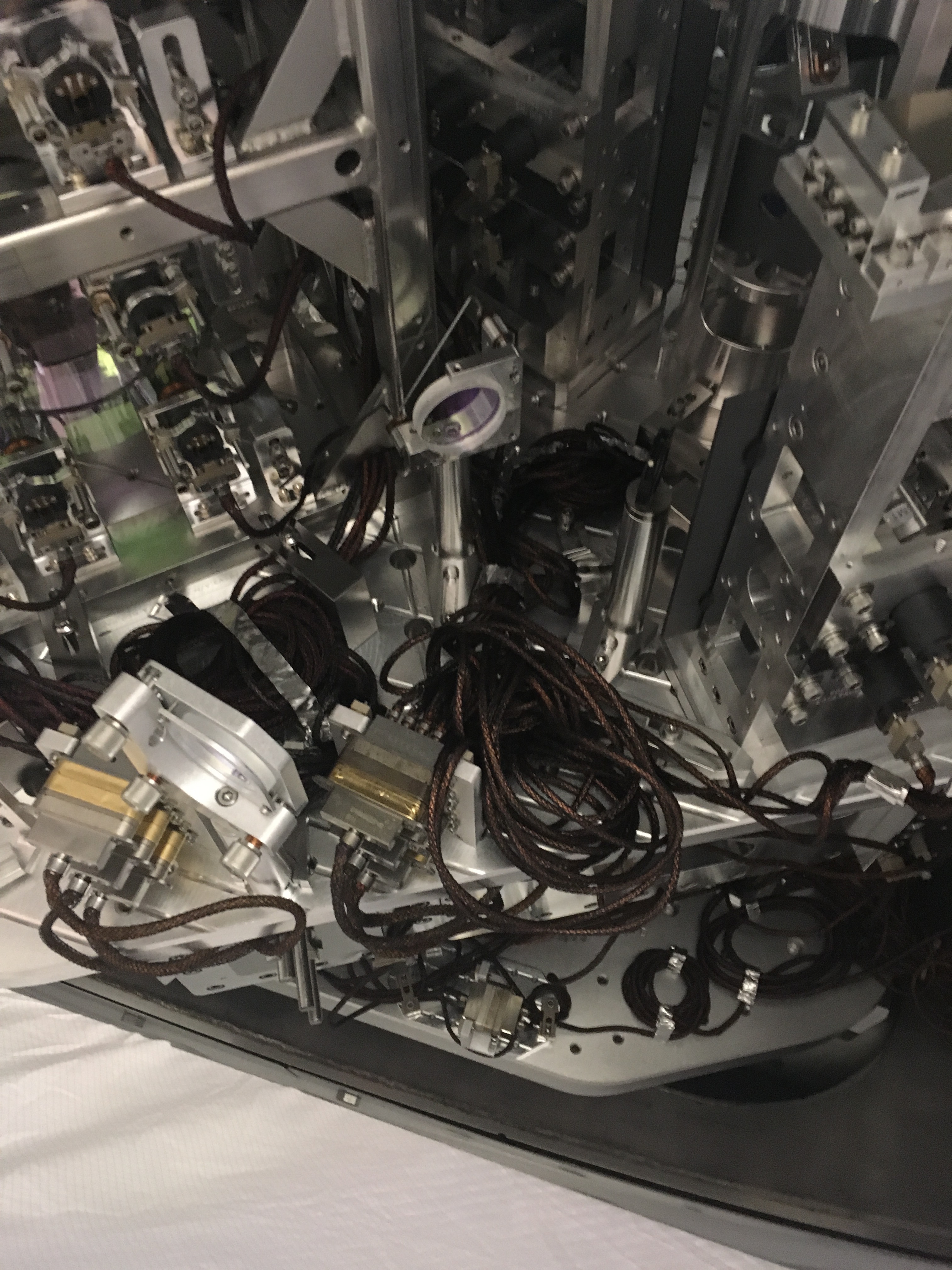
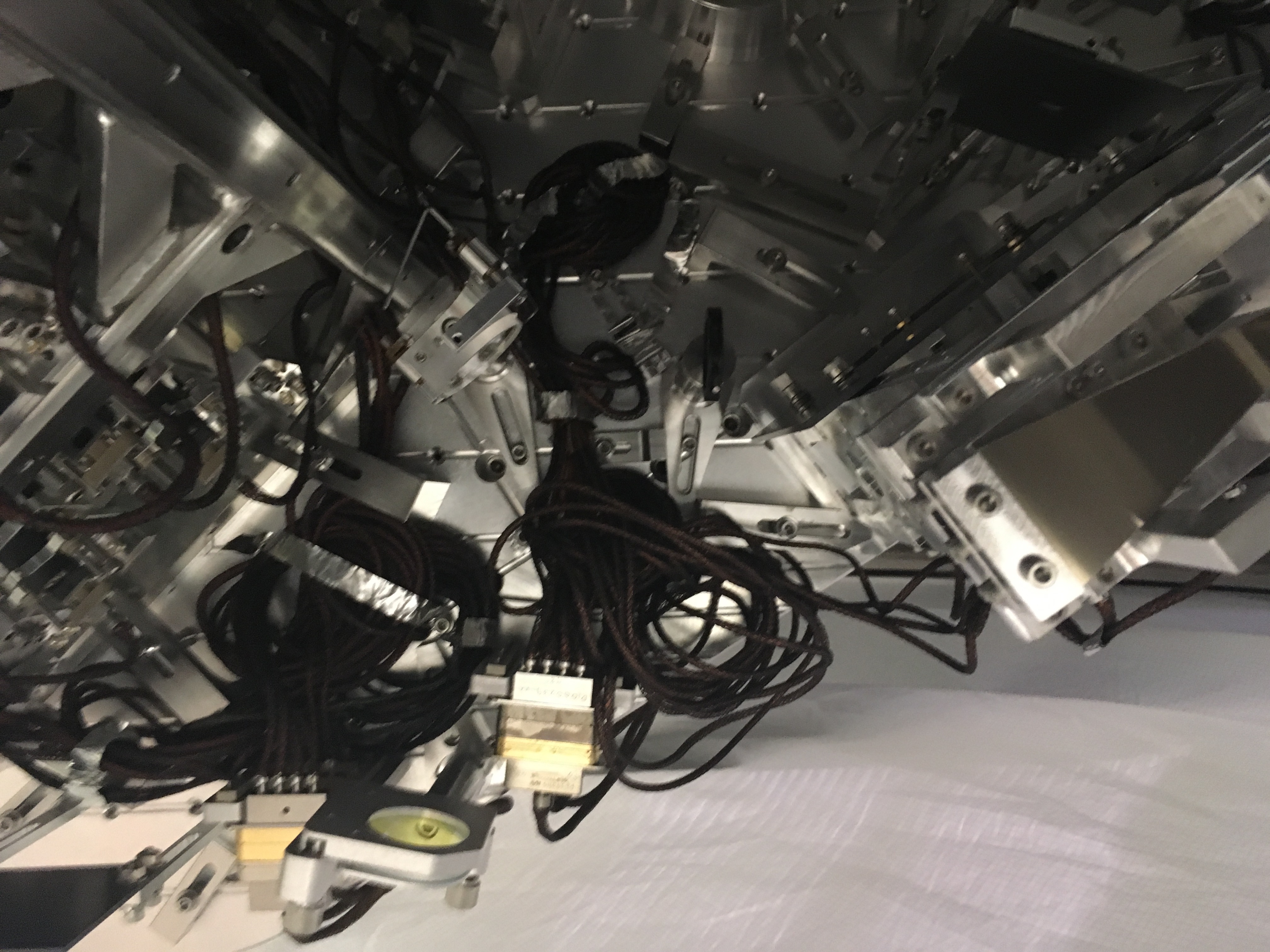
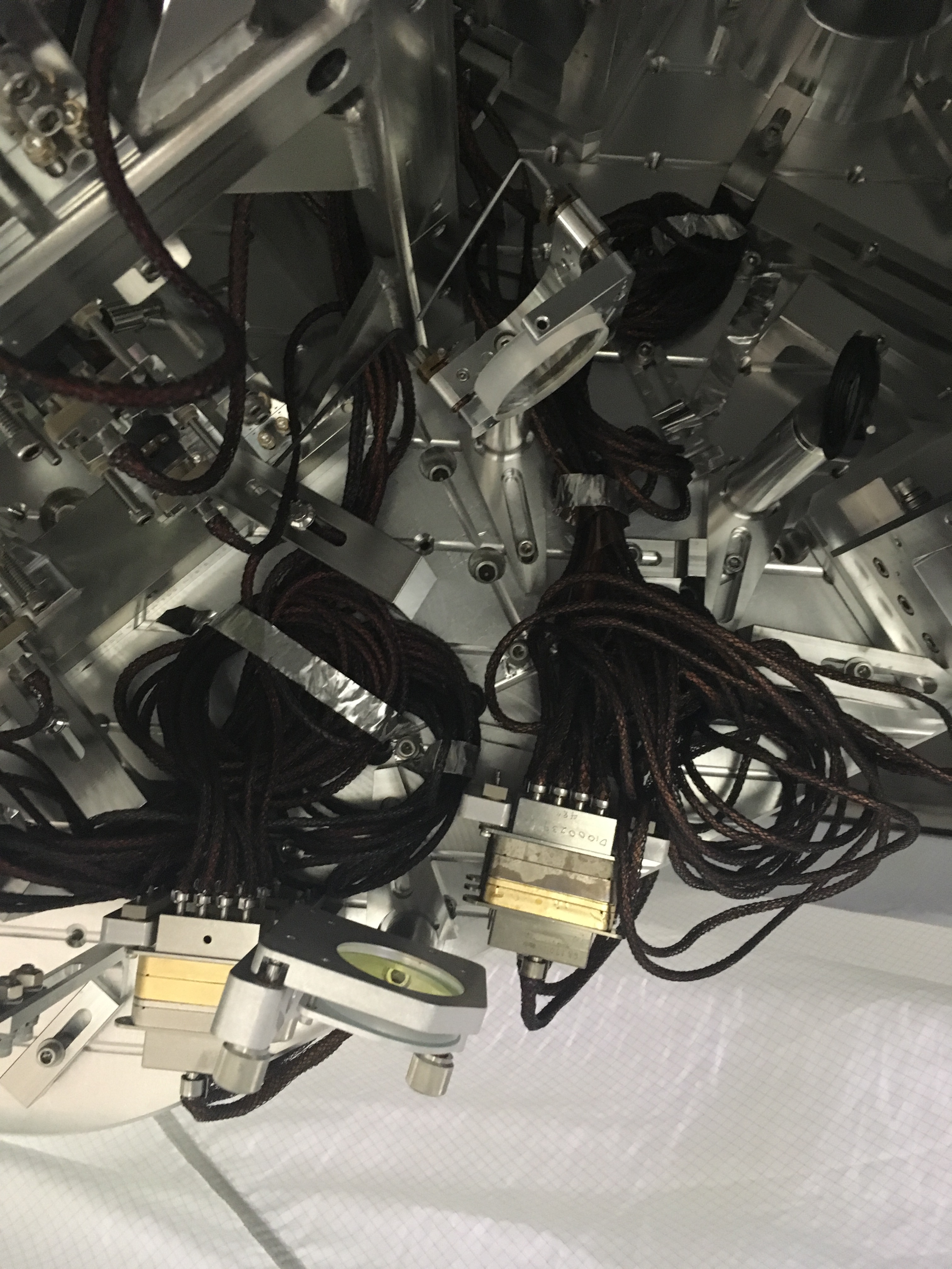
J. Driggers, S. Dwyer, G. Grabeel, P. King, J. Kissel, E. Merilh, J. Oberling, R. Savage

We've finished in-chamber alignment work including aligning / checking beams incident on IM4 Trans QPD, the ISS 2nd Loop PD Array, and installed then used the temporary viewport simulator for the IMC REFL and Trans beams exiting the HAM2 in-vac table. (The temp viewport remains attached to the chamber).  Remaining tasks for tomorrow morning are to fine tune the ISS alignment using picomotors (Peter K) and moving IM4 cage a little bit in yaw to relieve bias which is currently on 80,000 DAC cnts for 2 osems.

For all of today's alignments, we used the flashing IMC beam, *without* the bypassing the input mode cleaner. We elected not to bypass because (a) we're heavily constrained on the amount of experts' time for aligning these systems, (b) there's sufficient amount of input power (still ~170mW) that we could easily see the beam all the way to the input of the ISS array (which is behind (less than) 50ppm transmission of IM4 (aka PMMT2, ~25 ppm Trans), and two 90R-10T beam splitters ROM LH1 and ROM RH4; see E1300206), and (c) co-aligning the by-pass to the IMC flashing beam is a HUGE time-suck with its current functionality. (See notes in comments below.)

Technically, although we've confirmed that the flashing IMC beam enters the ISS array box, Peter / Rick will continue to work with the in-vac steering mirror picomotors to center the beam on the ISS array's alignment QPD early tomorrow morning.

Also, for IM4 Trans, while we weren't able to physically see the beam on a card, we were able to see the beam on the QPD readout, which was showing signal synchronous with IMC flashing, according MC2 trans. The alignment  was 0.65 for P, -0.25 for Y (in "standard" normalized QPD units).

For IMC REFL, we adjusted nothing, and the beam came out as shown in the IMCREFL picture.
For IMC TRANS, we moved ROM RH2 (the steering mirror behind / in transmission of IM1) in YAW three full turns of the the allen key. This moved the spot position at the table port by about 45mm (we recreated a "virtual" table with a table measure), to move it from virtually clipping on the edge of the ring / viewport simulator. The beam now comes out of the "viewport" as shown in the IMCTRANS picture.
Images attached to this report
Comments related to this report
Here're some details of the failed bypass we installed today.

Drawing and pictures attached.
All pictures are of the 2017-12-18 configuration.
I attach the 2014 configuration from the last vent, (see LHO aLOG 12702) for comparison.
Images attached to this comment
Non-image files attached to this comment

More notes on bypassing the IMC:

LLO has followed the procedure outlined in section 2.5 and figure 3 of T1300327, which shows a configuration much like the 2014-07-10 configuration.
Examples from LLO: LLO aLOG 35957 and LLO aLOG 25361.

What inspired us to bypass in the 2017-12-18 configuration was merely that we found the first bypass mirror (i.e. that which first receives the MC1 REFL beam, closest to the edge of the table) rigidly fixed / dog-clamped to the table aligned in such a way that looked like it would bypass the IMC in the 2017-12-18 configuration, and we found the second bypass off to the side in front of MC3.  So -- maybe we invented a new way to bypass, or maybe this is a new way Cheryl invented to bypass (likely! she's smarter than us), and we just re-created it (albeit unsuccessfully).