After Jenne changed the IMC alignment, some serious optical gain was still missing for IMC locking, but the power of the MC2 transmission was decent, IM4 trans was decent, alignment was decent, LO level at demod was decent, and finally I got suspicious about the cables.
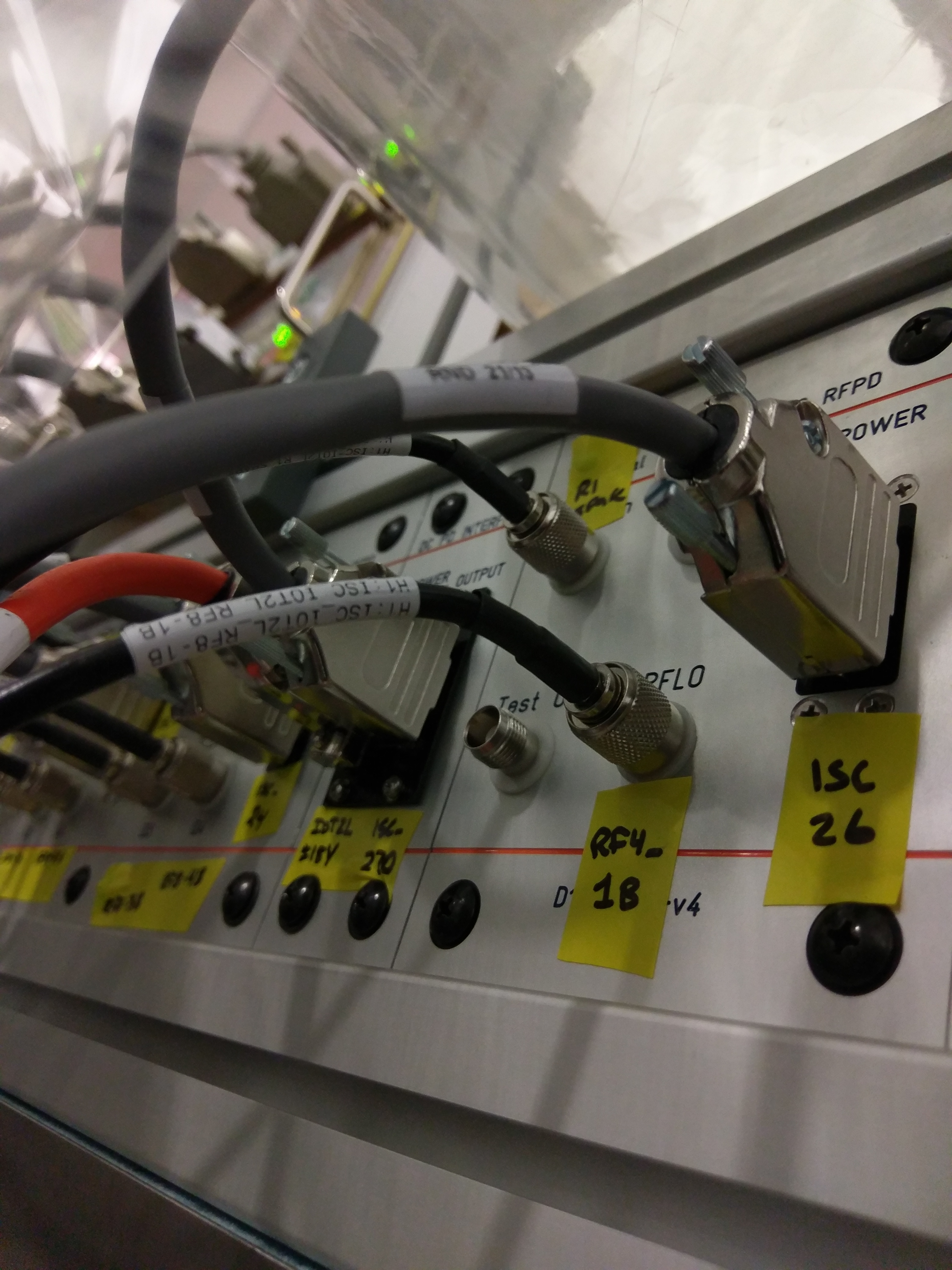
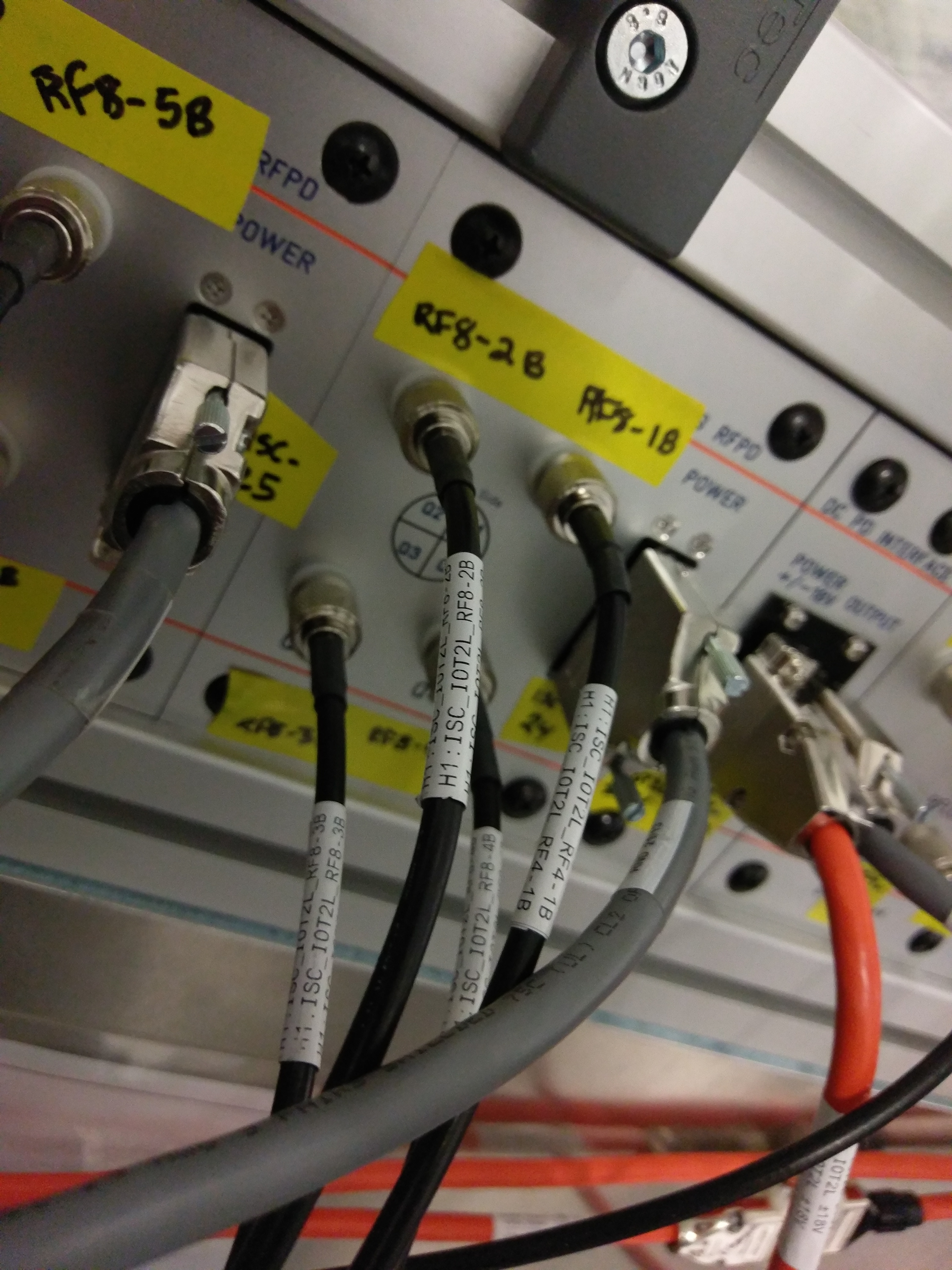
See attached, the first one shows the IOT2L feedthrough panel for IMC length diode. Connector for RF4-IB actually goes to RF8-1B, which is WFSA quadrant 1. The second picture shows that the connector for RF8-1B accepts RF4-1B.
So, all two weeks we've been locking the IMC with one quadrant of IMC WFSA, and we've been moaning that WFS doesn't work.
The connection was corrected, phase shifter was set back to the old setting (6.375ns delay) and the optical gain was back to where it should be.
Attached is an OLG measured with 1.95 Watts into the mode cleaner, 13dB of gain on IN1, the boost on, and about 110 uW on MC2 trans sum. UGF is about 45 kHz, so our gain is about what it should be.


To get the alignment back, I put the suspensions at the same places they were at around 17:30:00 UTC on 10 Jan 2018. At that time, I had about 118 uW on MC2Trans (with its whitening gain at the nominal 36dB), which is quite close to the O2 level of 130 uW for 2W of PSL input power.
Since Cheryl and I had (in the long weeks of confusion) tweaked the bottom periscope angle in the PSL enclosure, the PZT sliders from the 10 Jan time didn't match the alignment of the IMC, but within a few minutes of moving the PZTs around I was able to flash the TEM00 mode.
We were able to lock the cavity, but after the first UGF measurement Sheila and I found that the gain was much too low, so the rest of today we'd been using a slider value of +31dB on the IN1 slider of the IMC servo board (nominal is +13dB), and still weren't getting a UGF as high as we should. We checked the phasing of the I/Q outputs of the demod board (while the incorrect WFS quadrant was being used as our length PD), and found that we needed to add 4ns of delay to get the signal all in I. After much investigating and Keita found the mid-plugged cables, we rechecked the phasing with the correct RFPD as the input to the demod board, and found that removing the 4ns delay put us back to being all in the I-phase. So, the phasing of the IMC RFPD was correct all along, if we had been using the correct PD.
After that initial lock after moving the PZT around, we've consistently been getting about 120 uW on MC2 Trans (but still didn't have enough gain, which kept us on our investigations, which led to Keita's finding the cabling error).
I am now able to engage the WFS loops. If I move the PZT and have the WFS loops follow, such that the MC2 Trans PD is centered at the location where Cheryl had it in-air, I start to lose cavity buildup. So, for now I have found a location that roughly maximizes the buildup, and have used the digital offsets of the MC2Trans pitch and yaw filter banks to set this location as the setpoint. Now the full IMC ASC is on (WFS loops + MC2 Trans centering).
Also, now that we have the correct error signal for the length loops, the IMC guardian works again! We'd been hand-locking the IMC for the last few weeks (rather than rewriting all of the settings in the guardian while we were still confused). It's so nice to have the guardian back!