Some might feel that the H1 BS is more susceptible to tripping in an earthquake. The HEPI Inductive Position Sensors on the BS are outliers in that the vertical sensors have the most extreme values. Can't explain why this is the case but through installation and commissioning, these sensors have managed to get into an apparent tilted attitude. The HEPI could have actually done this through relaxation, strain relief, tension introduction; or maybe the sensors have been disturbed. The BS has had a Parker Valve replaced and this may have tensioned something or disturbed the sensor. However done, the vertical sensors read -6100, -14500, -7400, & +10800 for V1--V4 before I changed anything.
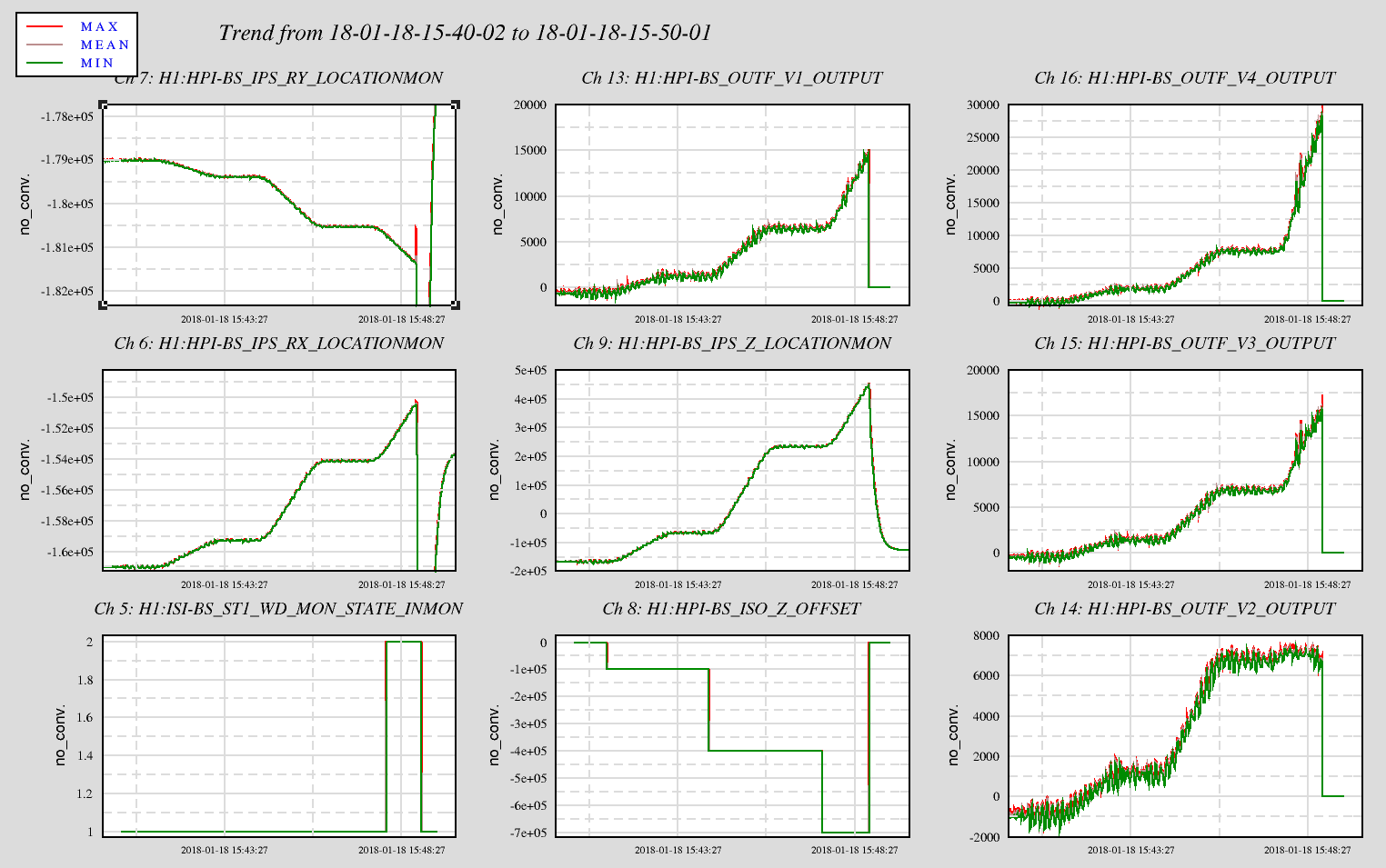
First thing done was stroke the platform in its isolated state. The platform tilted and tripped the ISI when the vertical offset went from 6 to 7 500 to 700um. When checking into the trip, I mistakenly looked at the OUTFs thinking I was looking at the IPSs. The first plot has the ISI_WD, HPI Tilts, the Z OFFSET & location and the Actuator vertical OUTPUTs. When I looked at this and saw that V2 did not move when the OFFSET was stepped to 700um and Z started moving up, I thought this must have been the reason for the trip. So, I went to the chamber and with the Z OFFSET at -500um looked at V2 sensor. With the IPS reading ~-2000 (now I was looking at the correct channels) and while the Actuator was close to the mechanical limits, I thought it should still have a little room to move up. Still, the IPS reading did not reflect the actual position; so, I deisolated and this put the Actuator about in center position and given that, zero'd the IPS. With this change, the Z, RX & RY computed locations changed and the TARGET POSITION for Isolation was adjusted accordingly. Re-isolated the platform with no difficulty.
So, since I was on the adjustment track of the IPS, I stroked Z again, this time in the opposite direction and drove to dZ = -800um and did not trip HEPI. Okay, back the other direction. The platform was fine at dZ = 600um but tripped while attempting to move further. This time I had the channels right and it was in fact the V4 Actuator causing the trip. At the chamber, even without the Z OFFSET, the V4 Actuator appeared to be at the mechanical limit. Not sure where it was getting the ~14000ct stroke but certainly no surprise it was stopped and caused the trip; apparently lots of distortion.
I did not adjust the V4 sensor position as I did not see that getting us anything and for it to trip at ~24000 cts is not terribly unreasonable. So, sadly, the BS HEPI is limited in its upward vertical stroke and correcting this will require disruptive action: The Actuator will need to be in effect, disconnected, recentered and reconnected. Suspect I can do this in a few to several hours....
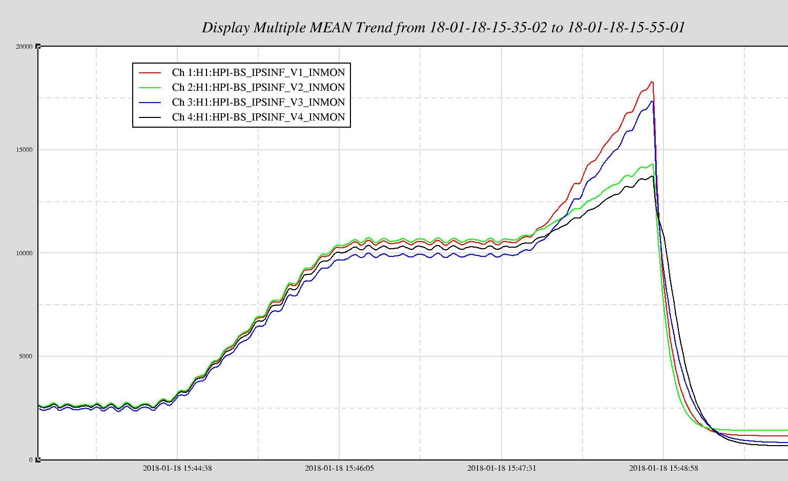
The second plot has the four IPS with Y normalized to zero back earlier. The flat line in the middle is with the dZ at 600um and the ramp following is when the offset was set to 700um. Comparing the previous ramp up from 500 to 600um, clearly V2 and V4 are unable to drive like V1 and V3 and also not as well as on the previous ramp up. Given the visual checks, I don't think V2 is mechanically limited but I certainly think V4 is limited. So, it is interesting both V2 and V4 show the same trend. Maybe the limit on V4 causes a platform distortion that V2 sees? Ah ha! All DOFs loops are closed and this is what is required to keep the tilts right. Need to do local motion tests to see if V2 is in fact limited but not today.
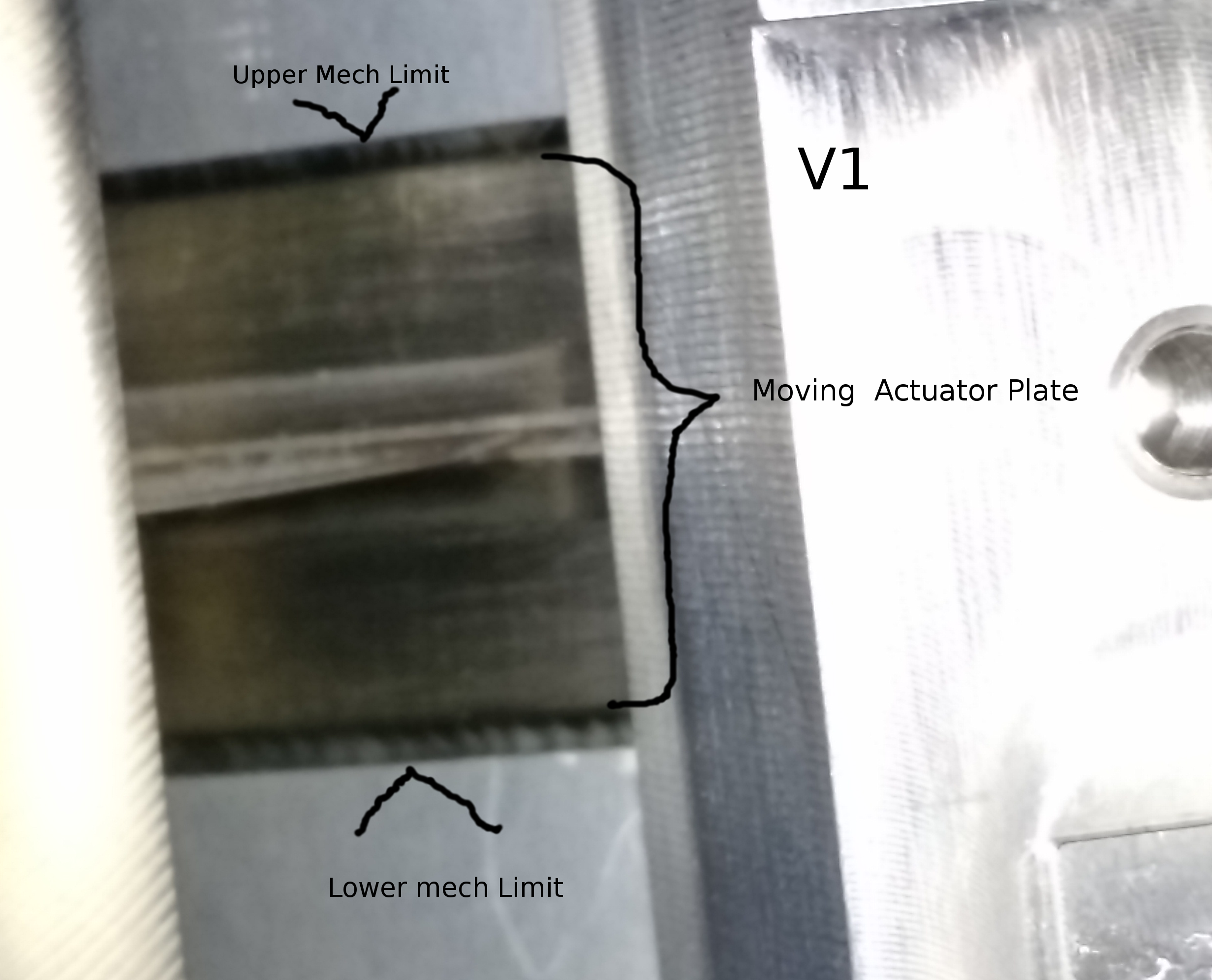
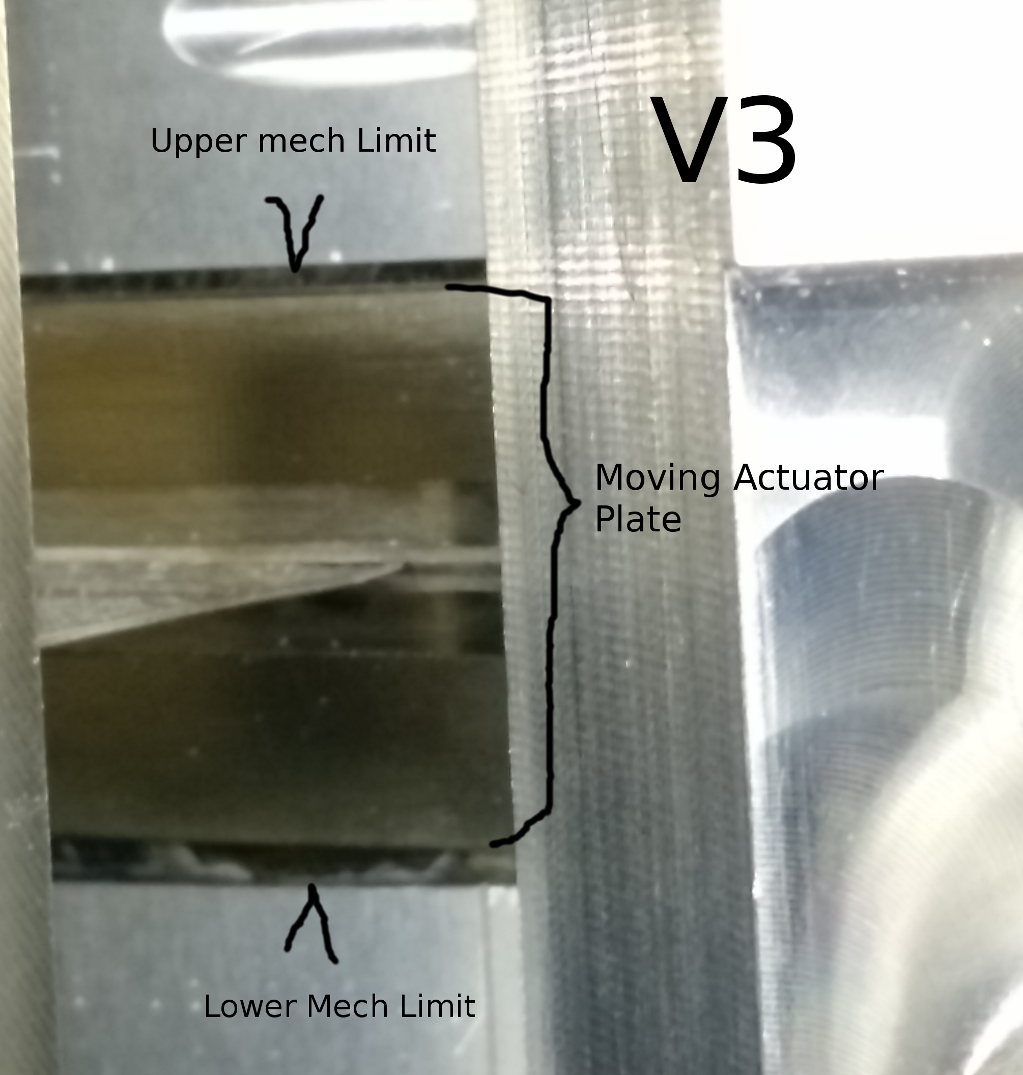
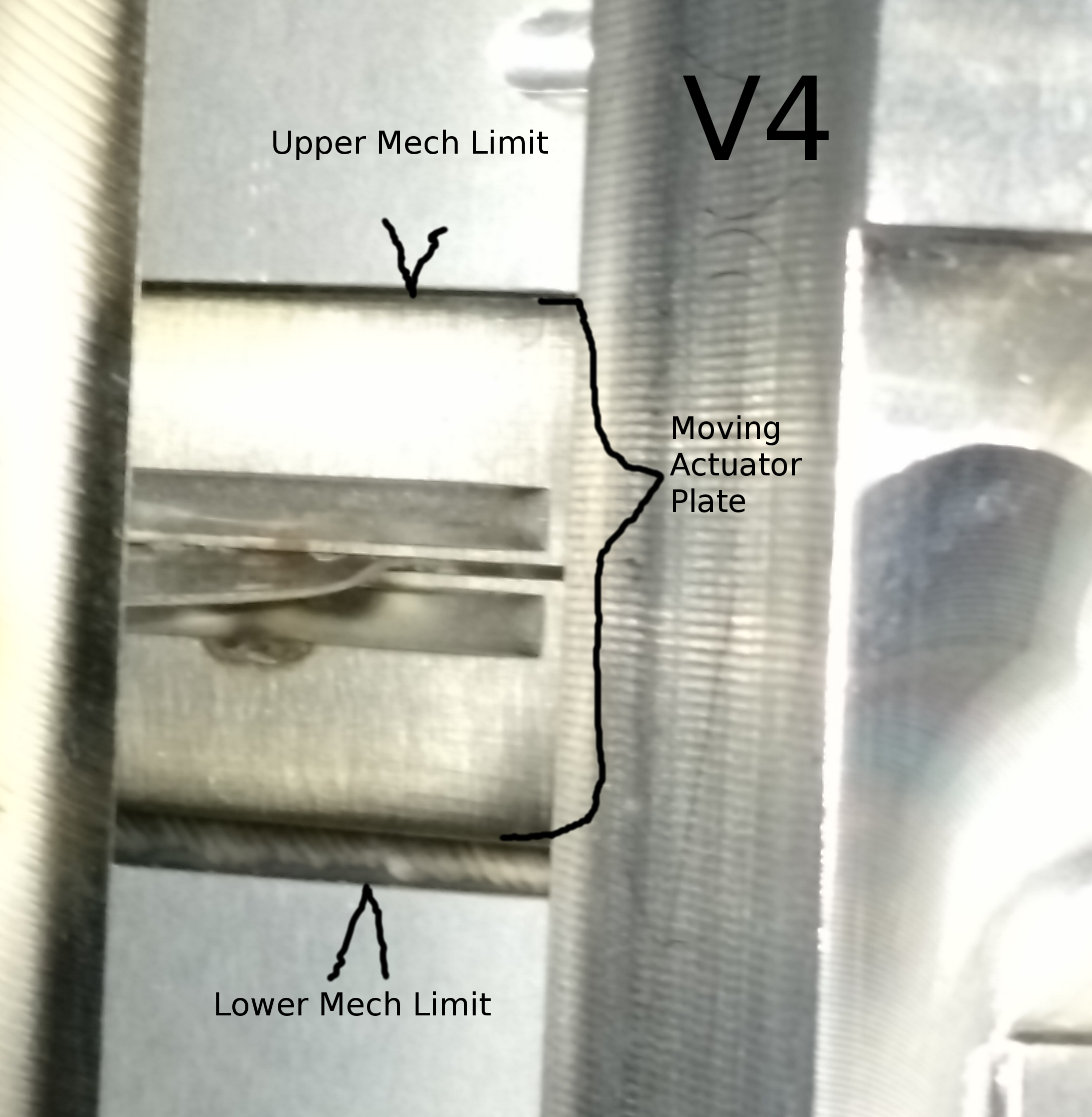
Before concluding this invasive work for the day, I took photos of the four Actuators to look at the ~position within the mechanical limits. These were taken while Isolated but no offsets and the V1--V4 position sensors reading -6100, -2100, -7400, & 10800cts. V1 & V2 look pretty much the same and centered so I don't attach V2 ( also for some reason the V2 file was 4 Mb.) V3 is slightly high of center and V4 is visibly near its mechanical limit.
WP 7297