Terry, Nutsinee, Daniel, Sheila
LAYOUT
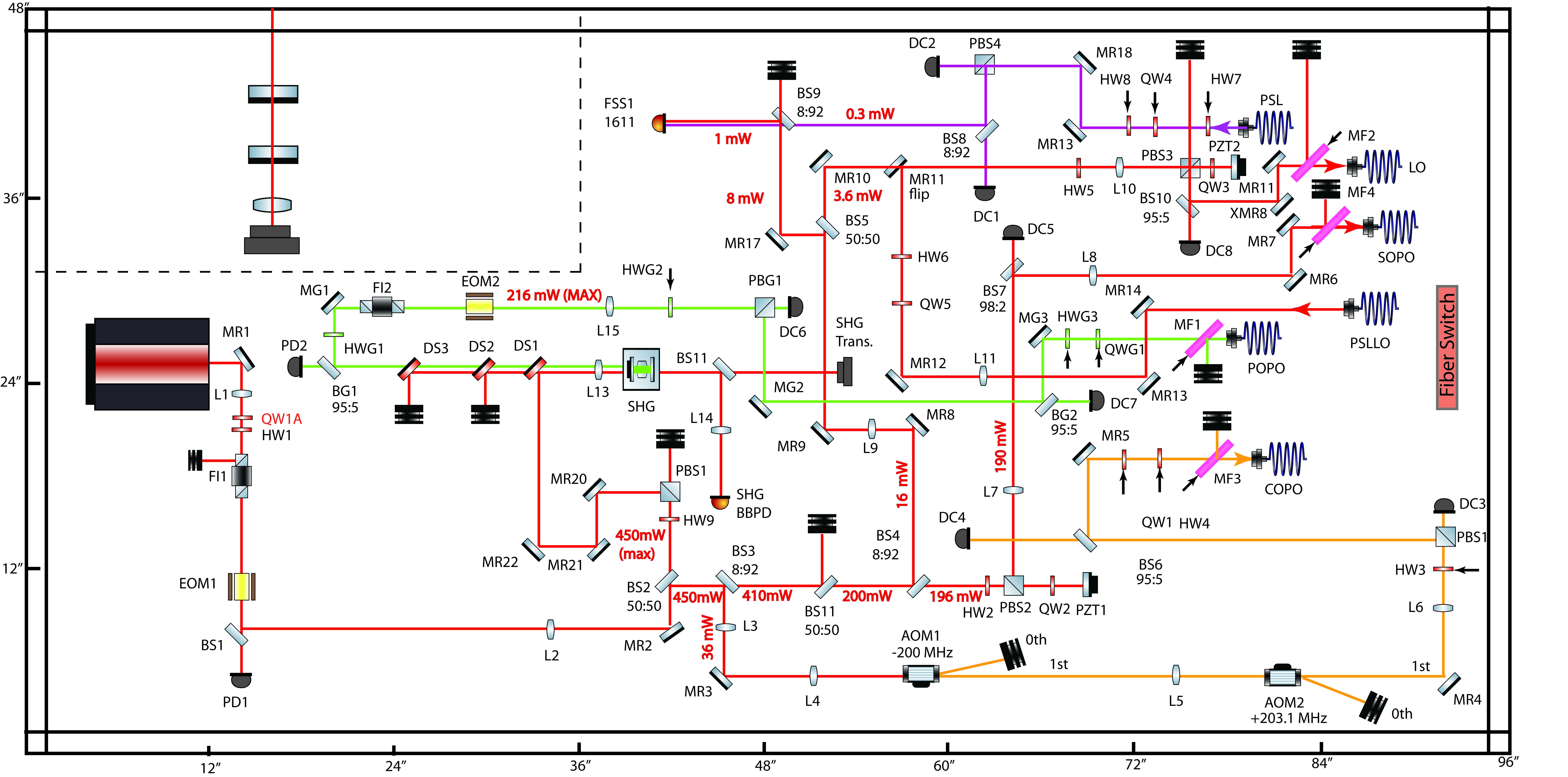
Attached is the current layout of ISCT6 at LHO that is an almost identical copy of LLO. Differences at time of writing are as follows:
1) A quarter wave plate was added after the laser to reduce the elliptical polarisation out of the Mephisto and increase the transmission through the isolator to > 95% and reduce the back reflection that is awkward to dump because the rejected beam from the isolator goes vertically down and is close to the isolator mounting post.
2) Two 100 mm & two 150mm lenses were used to mode-match the LO and PSL LO paths (instead of four 100 mm lenses) and the seed path has two 75 mm lenses instead of two 100 mm lenses as we had run out of 100 mm lenses. This made the LO path from the PSL about 50 cm longer and the seed path a few cm shorter. The seed path was routed as originally proposed in D1500297-V5 as a lens mount was in the way and made it difficult to keep an exact copy of the LLO beam path.
3) The SHG is about 5 inches closer to the fiber coupled output end of the table than at LLO. This was just a positioning error on the table and did not compromise the setup and once the SHG was mode matched I did not feel it was worth changing.
4) The fibre couplers are about 3 inches further away from the end of the table (I accidentally left myself a little too much room to play with).
5) The fast AOM has 70% diffraction efficiency (as opposed to 80% at LLO).
6) To get more RF power on the TTFSS detector BS5 and BS9 have been swapped from their original positiions at LLO (alog 40249)
I'll post the mode-matching solutions shortly but the coupling efficiencies into all the fibres are about 80%.
PARTS LIST
The parts in red have to be replaced with superpolished mirrors and the parts in yellow are also not superpolished but are less critical.
Still waiting for fibres from couplers on table to patch panel and fibre switch (using temporary patch cables at the moment).