jeffrey.kissel@LIGO.ORG - posted 19:58, Monday 05 February 2018 - last comment - 18:23, Tuesday 06 February 2018(40427)
H1 SUS OPO Simulink and MEDM Infrastructure Mostly Upgraded
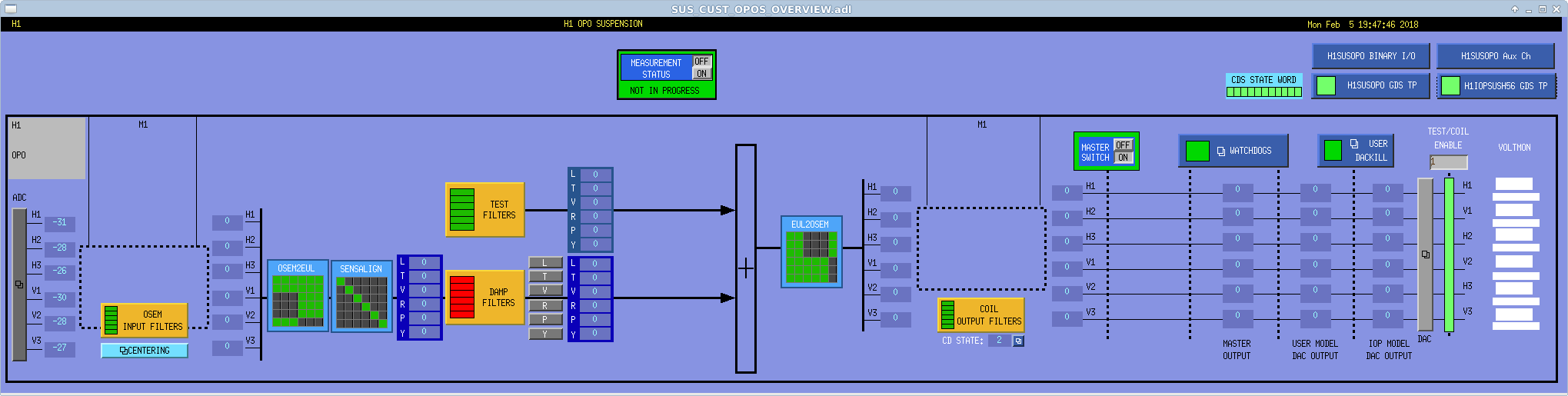
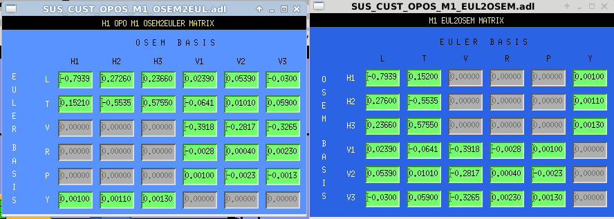
J. Kissel, D. Barker

A while back, I'd put together Simulink infrastructure for the OPOS (optical parametric oscillator suspension; then called VOPO) while we were beginning to rearrange the SUS HAM56 ADC / DAC allocation to accommodate the new squeezer suspensions (see LHO aLOG 38827). Since then, we've decided several things we'd like to change:
    - We don't like a suspension type and an instance of that suspension type to be the same. So, VOPO and VOPO gotta go.
    - We don't call the output mode cleaner the "vacuum output mode cleaner," so, we've dropped the V in VOPO for the instantiation, and now the suspension type is OPOS.
    - We don't like the channel ordering H1 V1, H2 V1, H3 V3, in the digital system, because that's not how team seismic orders there sensors named the same way, so we convert to H1 H2 H3, V2 V3 V3 (see E1700390 for sensor arrangement)
    - The important axis of the OPOS is *not* aligned with the HAM6 ISI's Cartesian coordinate system, so we convert to every other suspension's coordinate system, i.e. Euler, i.e. L T V R P Y (see G1701821).
Also, I never actually got the MEDM screen infrastucture up to speed to match *any* model, let alone the above new requests.

Today, I updated the front-end code to meet all of the above requests, compiled it, Dave installed it and restarted the h1susopo process. After that, I've moved things around in the sus/common/medm/ userapps repo folder to changing things from VOPO to OPOS, updated a bunch of screens and the associated marco file, and committed it all to the svn.

I've also *begun* to fill in this infrastructure where I can, but it's not fully complete. OSEM2EUL and EUL2OSEM basis transformation matrices we copied by hand from TST aLOG 11396, 'cause the scripts that calculate the values need to be updated for the now-preferred channel order. I've still gotta
    - copy over damping filters,
    - re-check-in with TJ regarding magnet polarity for the COILOUTF gains,
    - fill in the watchdog signal processing filters, and of course,
    - we need OSEMs to include any open light current stuff in the OSEMINFs).
Certainly good enough until we actually hook up our OPOS to the readout and control system.
We also need to change the naming convention in the h1susauxh56 model (VOPO to OPO) so we can pick up the coil driver monitor channels that are always useful when debugging whether suspension is being driven.
Finally, I've made sure the SDF system's safe.snap is up to date with all new settings, and committed that to the repo as well.

Attached are a few screenshots and a text file with more detailed notes about what needed changing -- especially the details of the top-level front-end model changes.
Images attached to this report
Non-image files attached to this report

Comments related to this report
J. Kissel
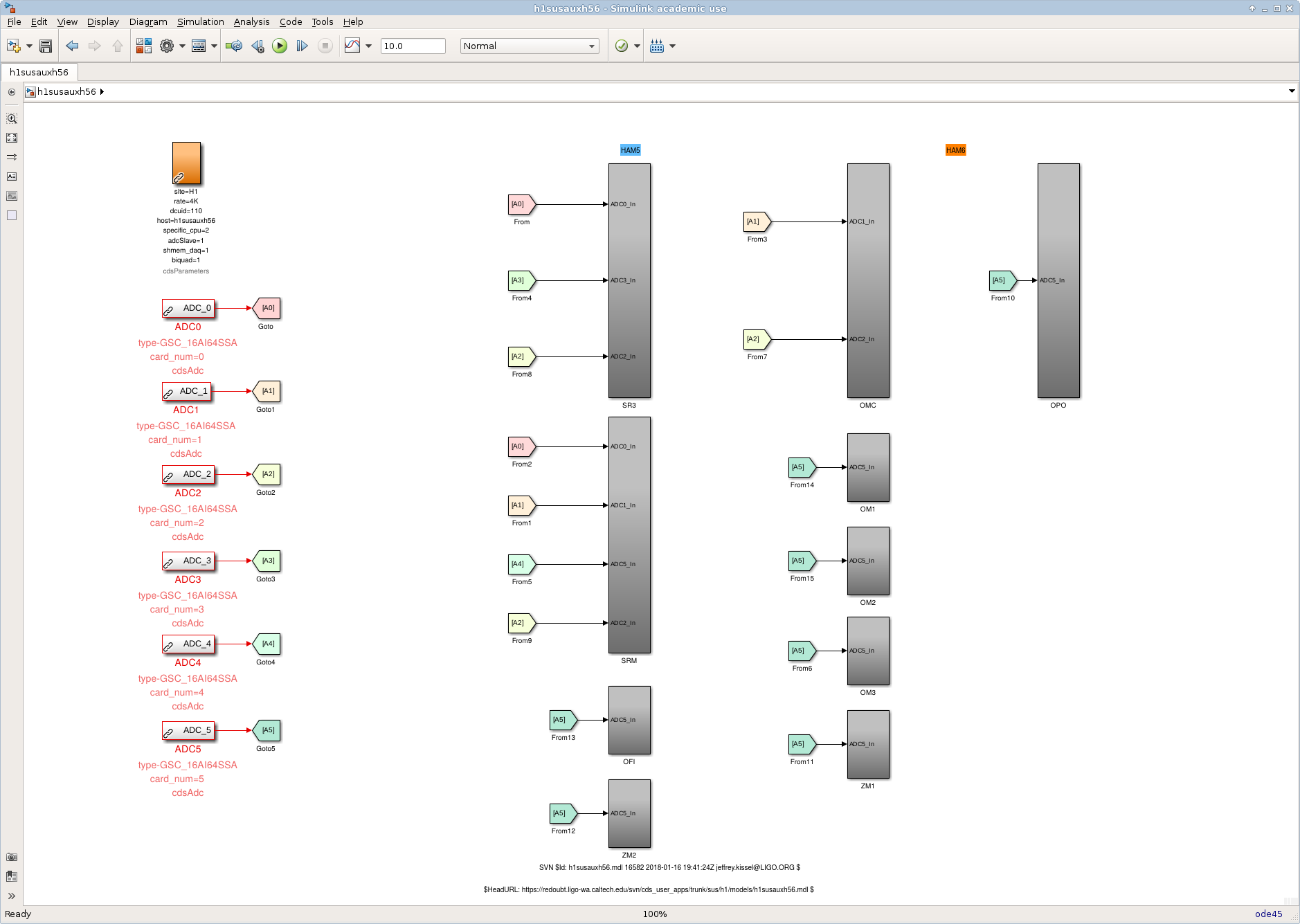
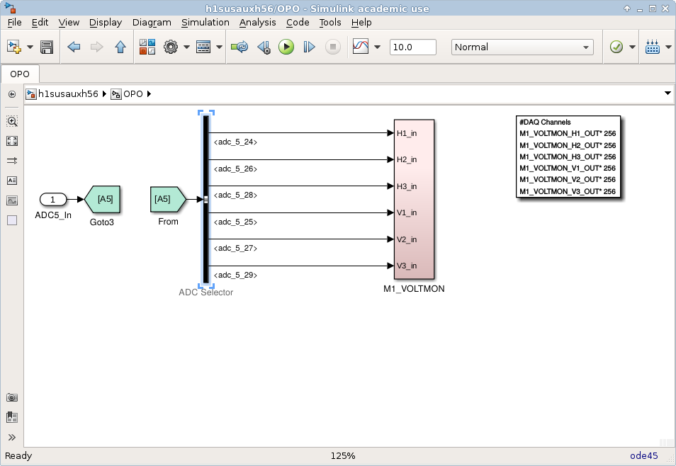
I've made the necessary name changes to the h1susauxh56 front-end model and the associated channels on the OPOS overview screen. The auxiliary model has *not* been restarted, since I don't want to demand a DAC restart on the arm peak team.
We should install the code and restart the h1susauxh56 front-end process as soon as is convenient.
Further MEDM and settings updates:
- I've updated the overview screen to include a diagram of the relationship between the OSEM coordinate system and the Euler coordinate system, a. la. E1700390.
- I've converted the coil driver monitor screen (which was a totally incorrect copy of a HAM triple's monitor screen) into a standard, six-channel, filter bank screen. This allows for calibration of the voltage monitor signals, if we so desire. Remember, the OPOS AOSEMs are driven with an HAM-A driver which *only* has voltage monitors, unlike core-optic suspensions which have the full NOISEMON, VOLTMON, FASTIMON and SLOWRMSIMON collection of monitors, and it only has one isolation stage, so a fancy screen in not needed here. (Since the h1susauxh56 model with corrected channel names has not been installed, the screen remains full of white EPICs records.)
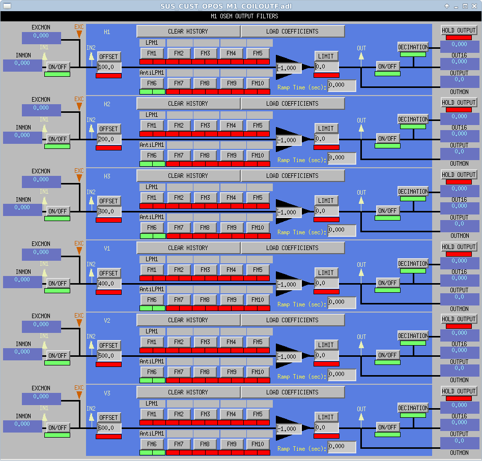
- I've installed COILOUTF coefficients: they're all negative. See explanation below.
- I've installed filtering on the OSEMs for the OPOS watchdog. Remember, this is one of the first suspensions to receiuve the updated watchdog infrastructure (see E1700387) so it now, not only has a 0.1 to 10 Hz bandpass prior to the cdsRMS part that all , but a 10 sec "averaging" filter (i.e. a 4th order butterworth low pass filter with a corner at 0.1 Hz) after the cds RMS part. Y'know, like you're supposed to with an RMS calculation. We'll see how it goes once we hook up OSEMs. We'll also then decide how to calibrate the signal and set the threshold.
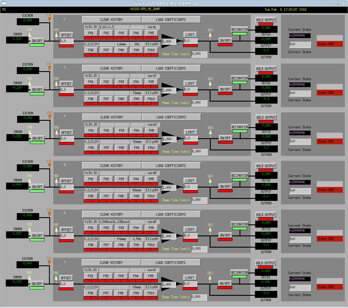
- I've copied over the damping filters from LLO, using that which was committed to
cds_user_apps/trunk/sus/l1/filterfiles/L1SUSOPO.txt rev. 16732 (last changed rev. 16627)
Spying on LLO, I've found that although there are lots of filters in each bank, only one is used (FM6), and the gain field is otherwise populated with gains something like what's mentioned in LHO aLOG 11390. I'll have to have a conversation with Stuart / Arnaud before I claim I understand what's happening.
After these changes, I can definitely say we're ready for OSEMs.
OPOS COILOUTF Sign Convention Explanation:
To establish the sign I use +YAW for the horizontals, +VERT for the verticals, the existing EUL2OSEM matrix, the established AOSEM sign conventions requested regarding coil current vs. magnet polarity T1200015, and the physical orientation of the OSEMs found in the assembly drawing D1500295.
For +YAW, we wish for the OSEMs to expand (as per D1500295), i.e. to push the magnet away from the coil. Given that all OPOS magnets have N polarity facing in the OSEM (as per E1700390), we need a negative current across the coil to create a push with a N magnet (as per T1200015). The EUL2OSEM matrix retains the sign of the requested +Y drive (i.e. the Y to H1H2H3 EUL2OSEM elements are all positive), so we must invert the sign of the requested, +YAW * EUL2OSEM, drive signal to get a negative requested current on each OSEM. Thus the H1H2H3 COILOUTF gains shall be negative.
For +VERT, we wish for the OSEMs to contract, i.e. to pull the magnet into the coil. With the N polarity facing into the magnet, that means we need a positive current across the coil. The EUL2OSEM matrix flips the sign of the requested +VERT drive (i.e. the V to V1V2V3 EUL2OSEM elements are all negative), so we again must invert the sign of the requested, +VERT * EUL2OSEM, drive signal to get a positive requested current on each OSEM. Thus, the V1V2V3 COILOUTF gains shall all be negative.
Images attached to this comment
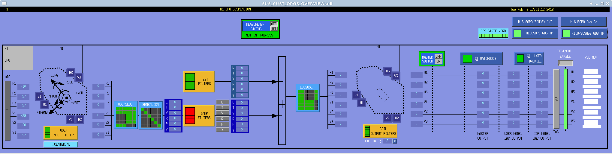

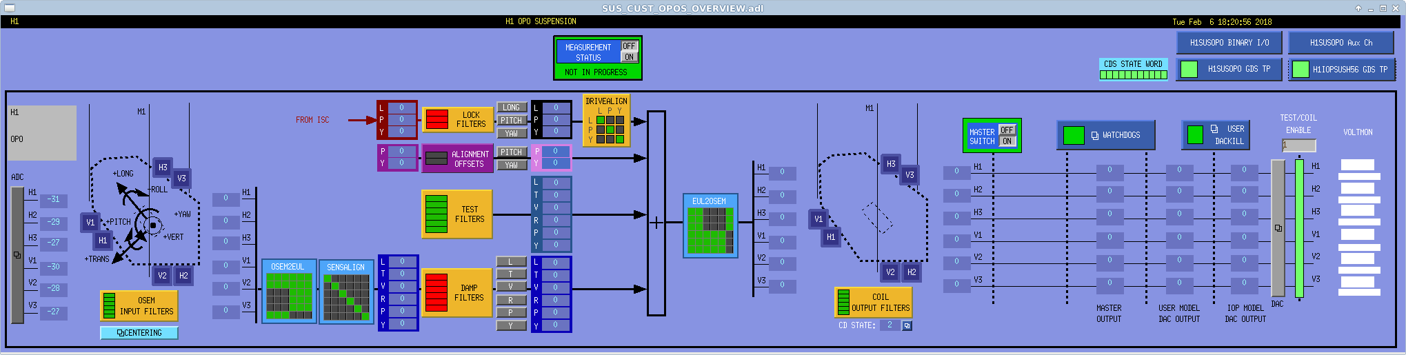
J. Kissel, S. Aston

Stuart rightfully noticed that although the OPOS_MASTER model had the usual OPTICALIGN, LOCK, and DRIVALIGN array of filters, it was not reflected on the MEDM overview screen. Whoops! I've now added all that and committed the screens to the userapps repo.
Images attached to this comment