We have measured the escape efficiency of our OPO by injecting 1064nm light into the input/output coupler to measure intracavity losses, we did this both before and after swapping the input coupler. Our final result for escape efficiency is 98.63+/- 0.03%, which means that we have 85+/- 36ppm of losses in addition to the transmission of M1+M2 in the cavity.
Set up
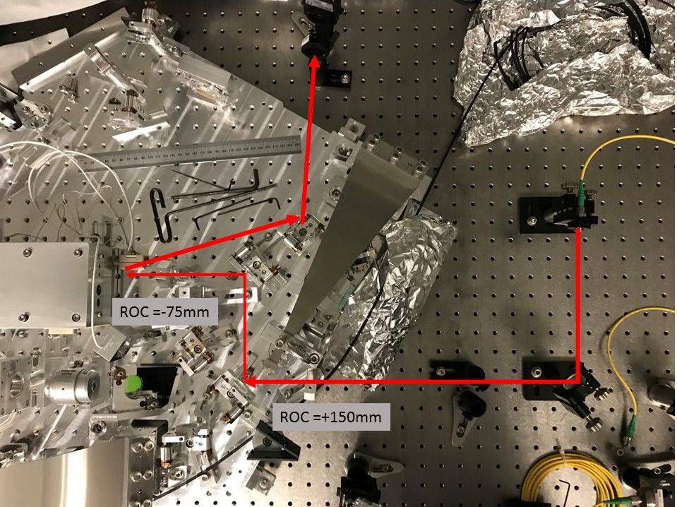
We set up a new optical path to couple 1064 into the OPO input/output coupler to make an escape efficiency measurement. On the optical table, we set up a Thorlabs fiber collimator F220FC-1064 (f=11.17mm), which has a waist of 437um at 1.13meters behind the collimator. The attached photo shows how we modified the squeezing output path and the green pump injection path to inject this. We left the -75mm ROC lens that was already placed and adjusted for the green mode matching in place, and added the ROC +150 lens for the translation stage temporarily at the edge of the platform to mode match this beam into the OPO. We had a different mode matching solution for the first set of measurements (taken before the M1 swap), but decided to try to improve the mode matching for the final measurements.
Measurements:
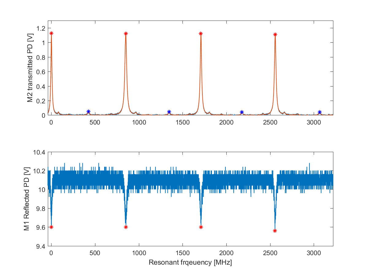
We scanned the cavity using the PZT on M2, and made a fit for the voltage applied to the PZT vs cavity length using the transmitted 00 peaks, in the same way we did for 40362 Both before and after swapping M1, we recorded data as the PZT scanned over 4 FSRs, so the results here are the mean and standard error of the 4 measurements. We estimated our mode matching using the peak heights (peak 00/(peak00+peak20)). The reflected power on resonance over off resonance is corrected to account for this mode mismatch assuming that there is a signal on the PD from order modes equal to V_{off resonance}*(1-mode matching) that contributes to the measured voltage both on and off resonance. This gives us an estimate of the round trip losses other than input coupler transmission, including the transmission of M2 who's reflectivity was measured to be 0.99818636 in E1800011. (Fabrice tells us that the mirrors installed in the H1 OPO before the M1 swap were serial numbers 37, 11, 6 , 8 for M1 to M4 respectively in E1800011).
The escape efficiency is given by ln(R_{m1})/ln(R_m1*R_loss) where Rloss includes all losses and transmissions other than R1. R_{m1}=0.87298077 before the swap, after. For reference I've also included the maximum possible escape efficiency before and after the swap, is the m2 transmission was the only contribution to Rloss.
| mode matching | reflected power dip on resonance | estimated dip with mode mismatch corrected | round trip loss (other than M1 transmission) | intracavity loss (excluding M2+M1 transmissions) | escape efficiency | escape efficiency with no intracavity loss | |
| Before swap of M1 |
90.4+/-0.1% |
94.8+/-0.1% | 94.2+/-0.1% | 2010+/-45 ppm | 201+/-45 ppm | 98.54+/-0.03% | 98.68% |
| After swap of M1 | 96.3+/-0.1% | 94.8+/-0.1% | 94.6+/-0.1% | 1900+/-36 ppm | 85+/-36 ppm | 98.63+/-0.03% | 98.68% |
More on mode matching correction
We tried to check that the correction for higher order modes reliable by taking one set of data where we intentionally misaligned the input beam, and attempted to correct for both the mode mismatch and misalignment higher order modes. This gave us an inconsistent answer, which is why we were motivated to improve out mode matching for the final measurement. I don't understand what is wrong with the higher order mode correction, that requires some more thought.
In the end, our losses are dominated by the transmission of M2, so this measurement gives us rather large uncertainty on the other losses in the cavity. We can be confident that the escape efficiency is close to the best possible for the selected transmissions.
After finishing this Friday we restored the green injection path, and worked on some of the remaining items on the VIP platform. There is some remaining work to be done on the VIP before balancing it.