Á. Fernández, J. Kissel, T. Shaffer

Álvaro, T.J. and I B&K hammered the optical parametric oscillator suspension's (OPOS) fully-payloaded bread board today, both with and without viton beneath its balancing masses. The reduction of bending mode Qs was about a factor of 2 to 3. Not very impressive -- my feeling is that we're either (a) putting viton where there is little bending, and/or (b) the balance masses do not provide enough moving mass at these mode frequencies to really suck out the mode energy through the viton.

I've not been tied close enough to this suspension to know if there is further action / improvement to make or take. Are there specific requirements we're trying to meet? Comment below if you have.
(Note, these results show that traditional, yet often broken, requirement of "Anything attached to the HAM-ISI must have its first bending mode resonances above 150 Hz" has been meet. Also, the addition of viton does not and will not have any affect on what ~1 Hz ISI - OPOS plant interaction issues Arnaud saw in LLO aLOG 37394.)

I attach the transfer function results.

We struck the platform vertically down at the outer edges, in the +Transverse corner and in the +Longitudinal corner (see E1700390 and/or G1300086 for basis definitions), and measured the response with the usual three-axis accelerometer. I only show the vertical response to each vertical excitation.

Stay tuned for pictures.

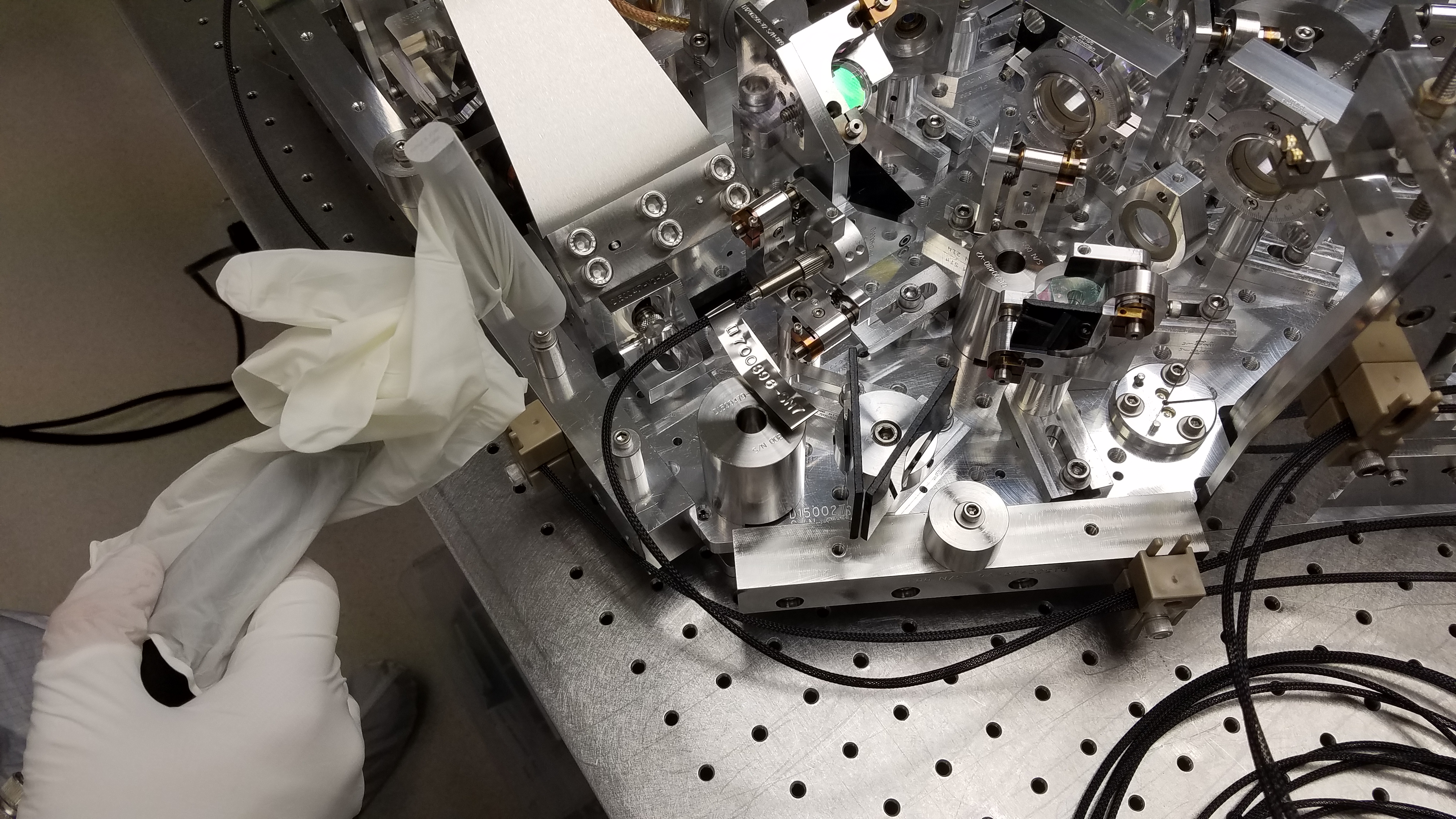
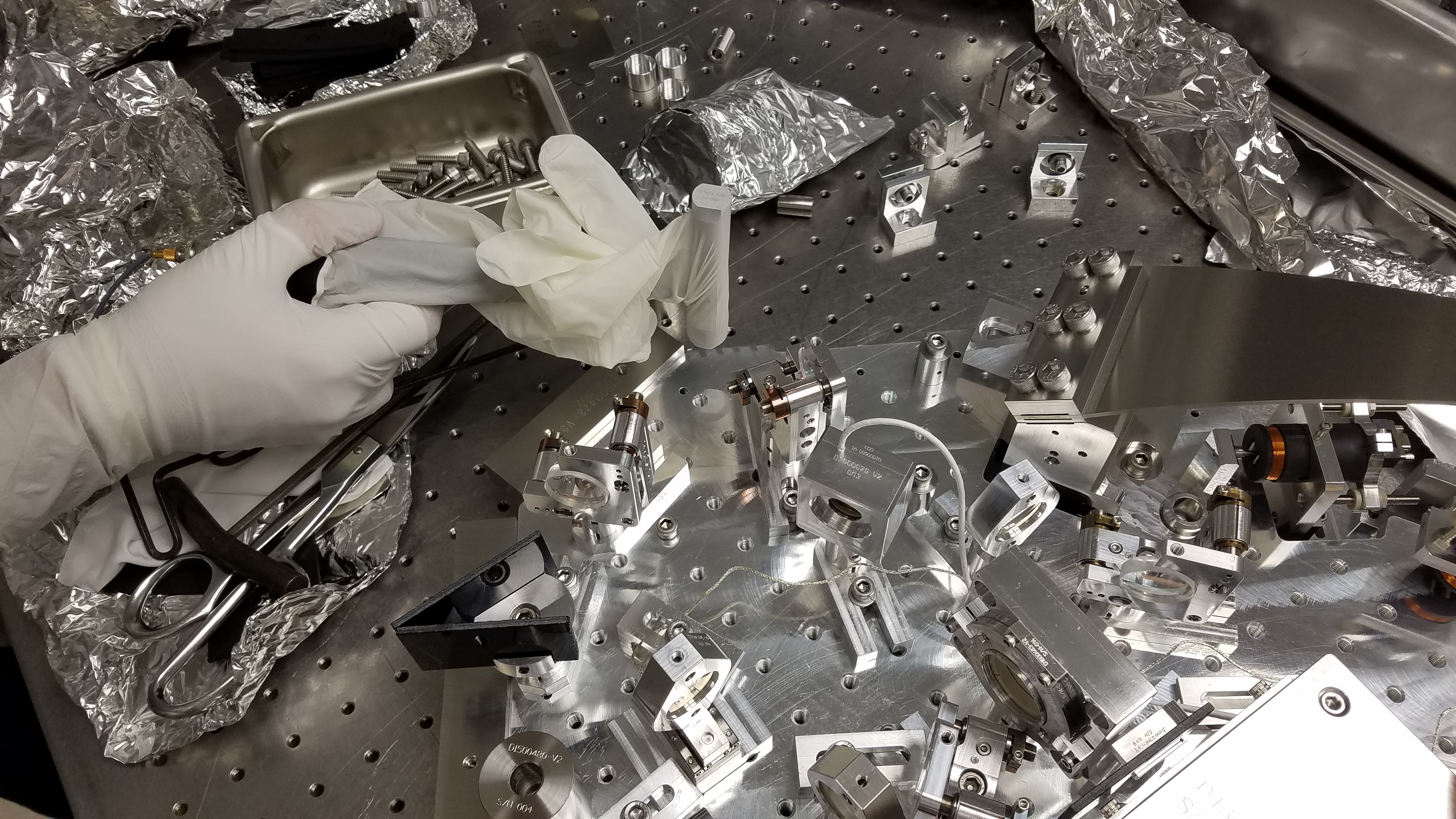
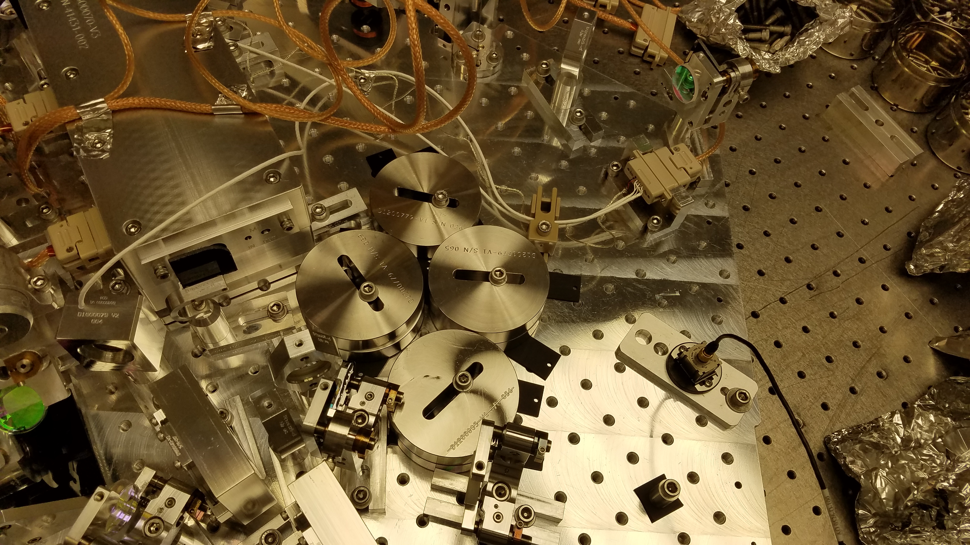
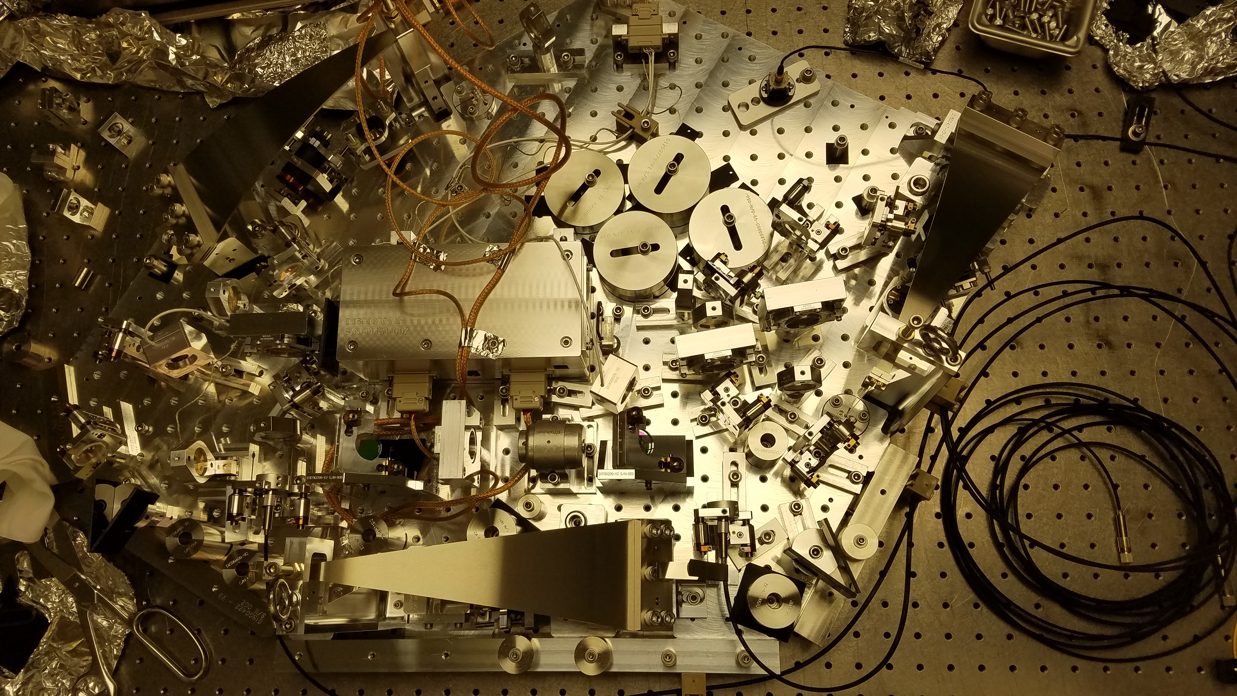
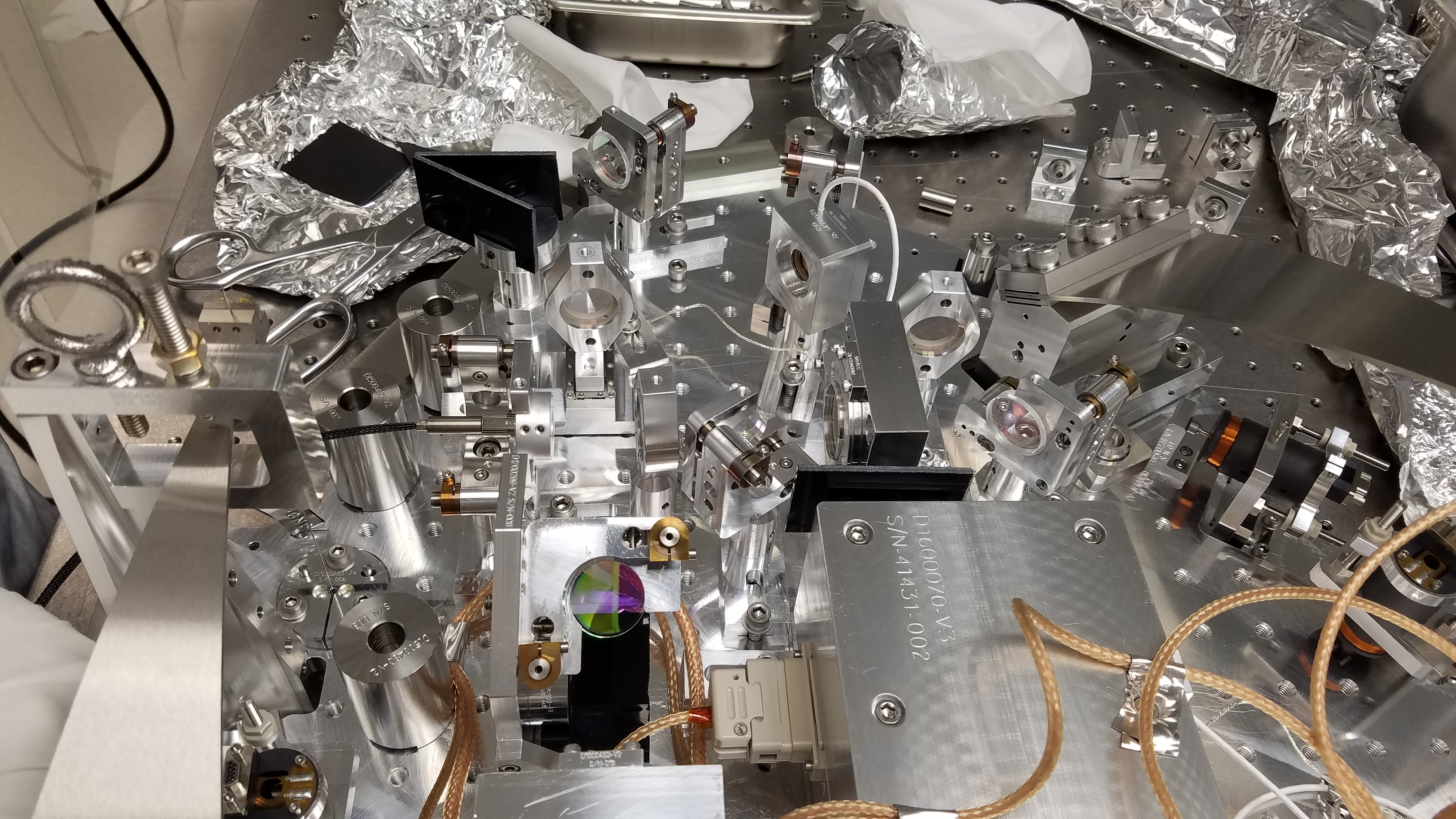
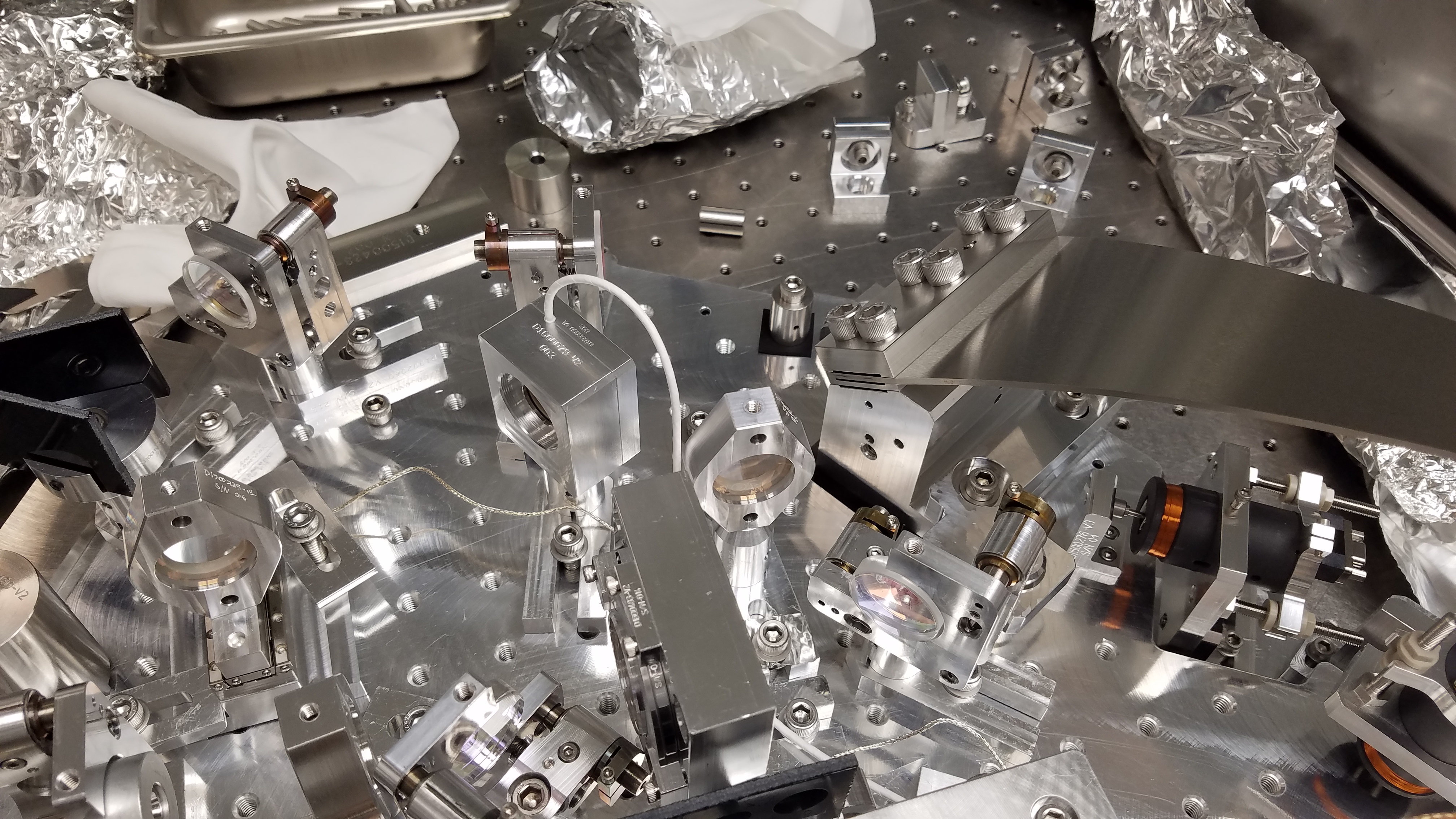
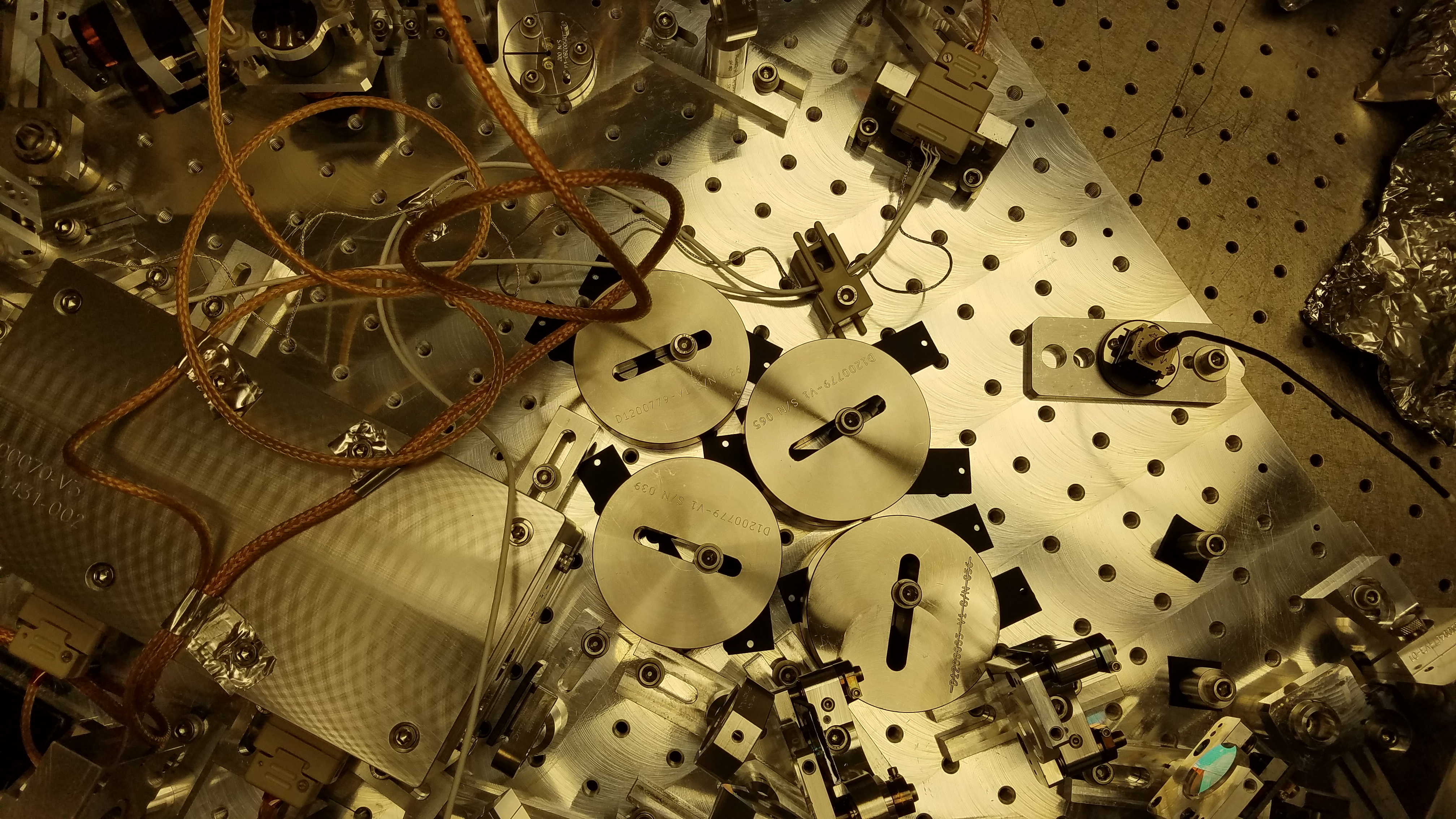
Adding some pictures of the accelerometer location, hit locations, and some pictures of the added viton. The viton we added was a mixture of some 1/16" thick pieces and some 1/16" thick tie down strips. We used these pieces mainly because it was what we had available. We adding viton to all of the large masses and then tried adding it to some of the smaller masses to try to damp some of the higher frequencies. Since we were hitting a floating suspension, Alvaro had to tap very lightly the floating platform itself, while I would watch one of the stops to make sure it didn't hit.
Attachments are:
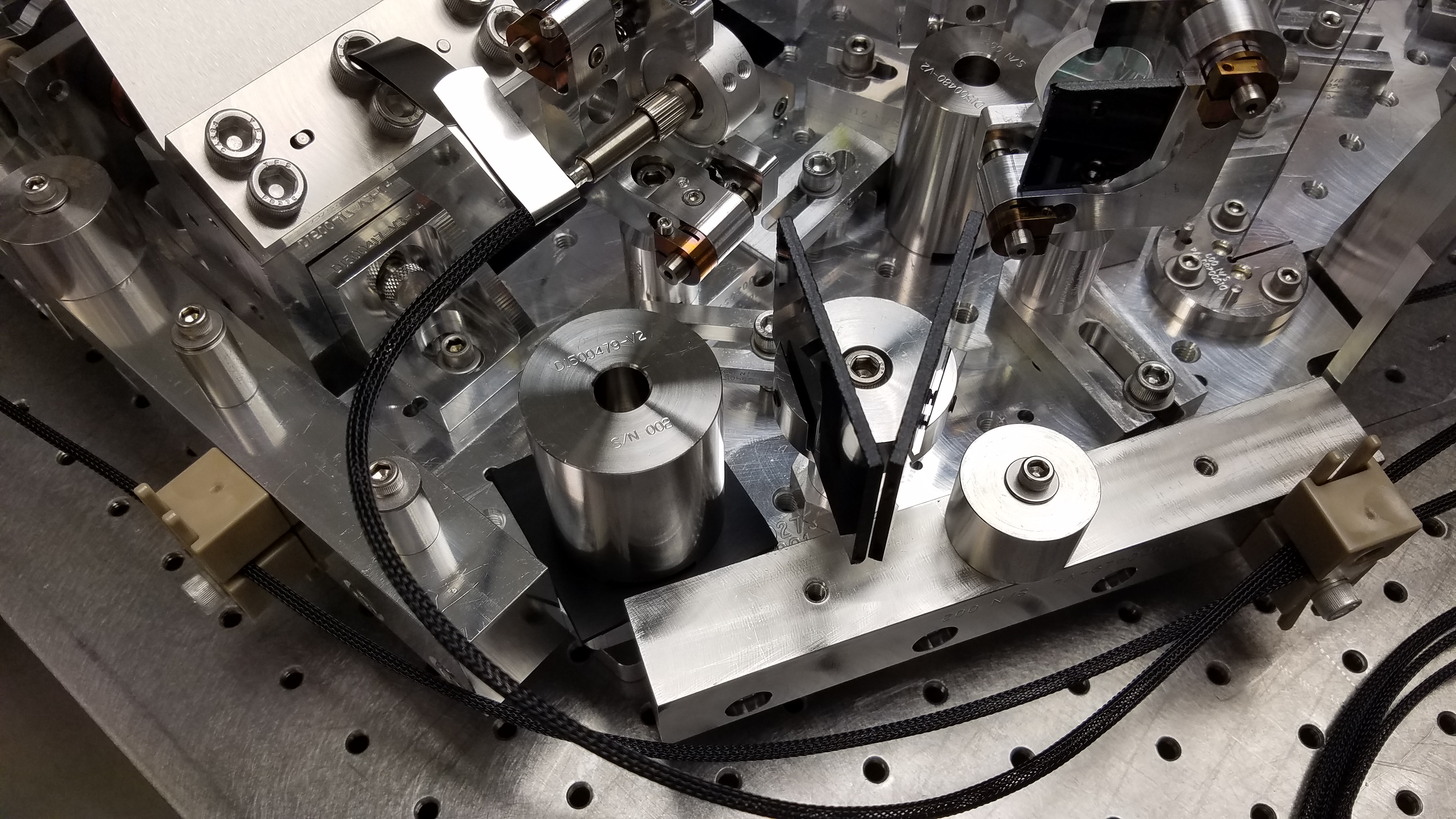
1 -- Hammer location one (+ transverse).
2 -- Hammer location two (+ longitudinal).
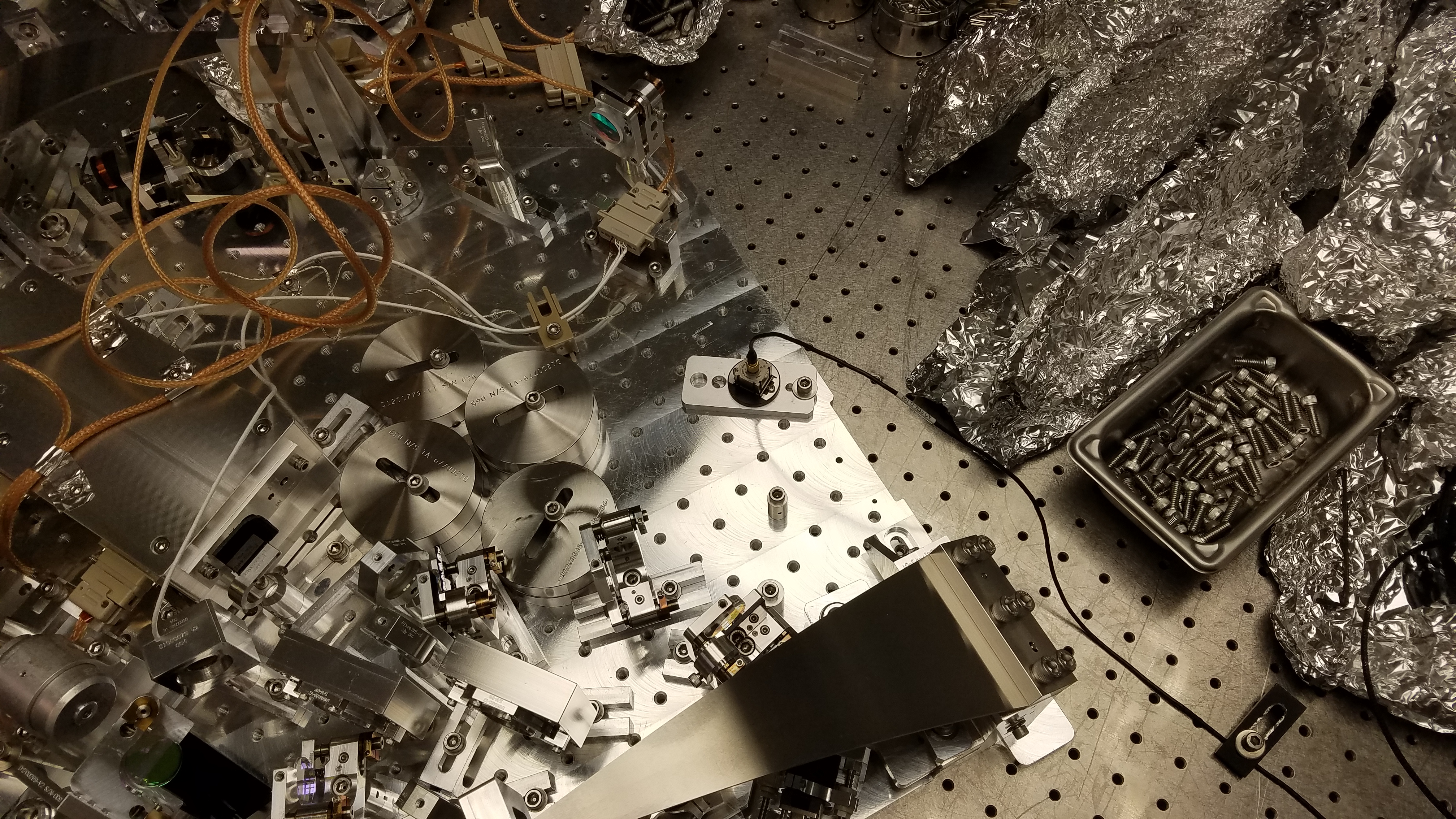
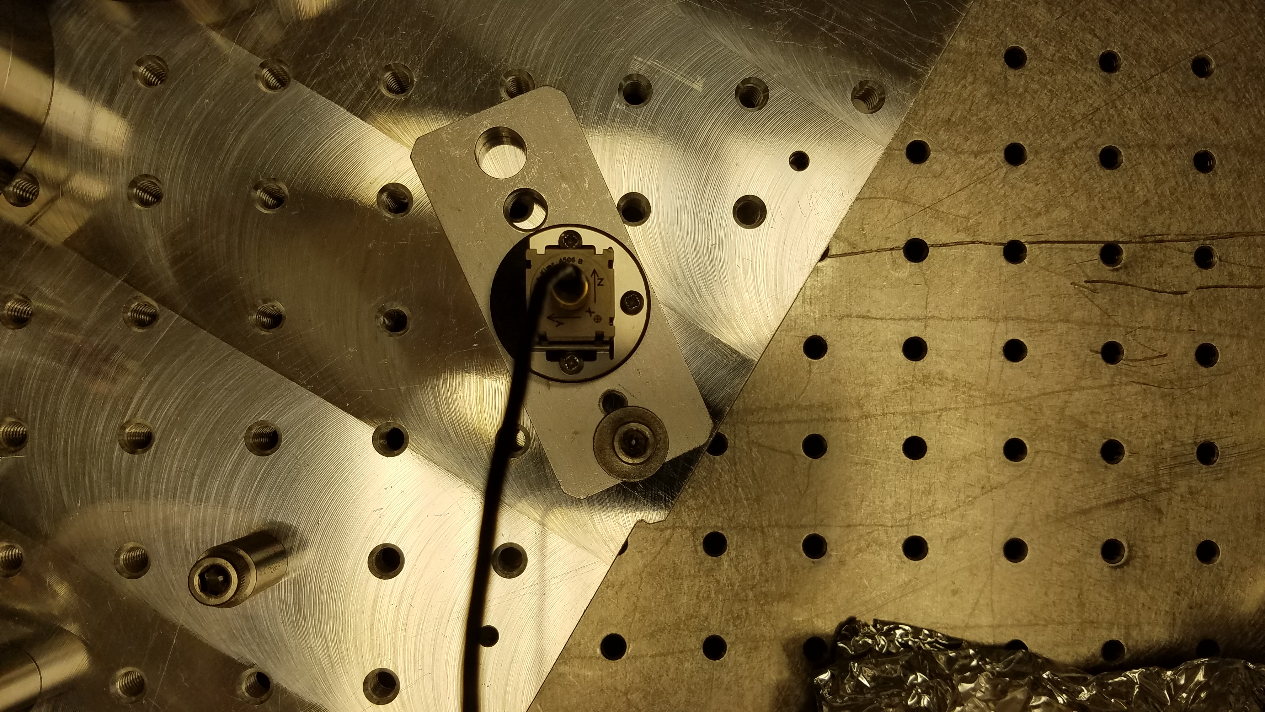
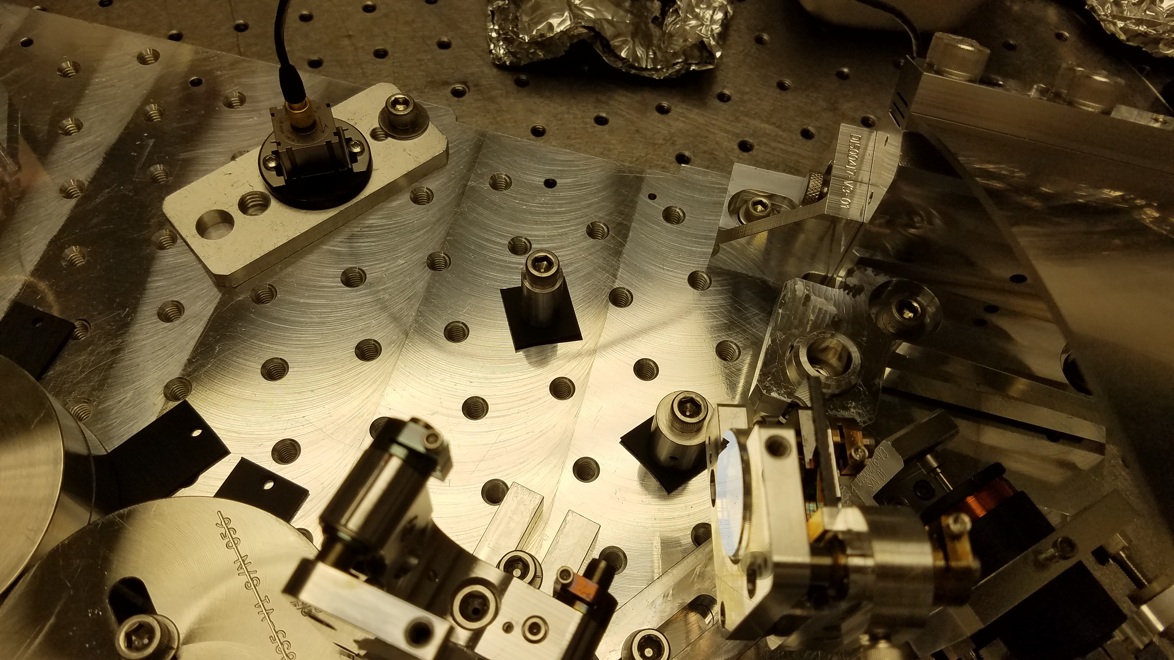
3 -- Accelerometer location.
4 -- Accelerometer location closer picture.
5-11 -- Various pictures of viton placement on the suspension.
I attach the raw data (.pls files), the exported data (.txt files), and the script used to analyze the data.


