Terry and I finished the final output paths of on the VIP last week and monday. The last thing that we checked with laser beams on the platform was adjusting the alignment through the Faraday to reduce the misalignment caused by moving the lens translation stage from one extreme of its range to the other. Alvaro helped us to check this using an iris about a meter away from the platform, when we started the beam was about 5mm lower with the translation stage at it's closest position to the Faraday than at its furthest. After we adjusted the pointing into the Faraday the beam still moves vertically up by about 1 mm as the lens is moved from the closest position to the Faraday to the furthest from the Faraday.
In the squeezing output path, we installed the dichroic 182mm from the edge of the OPO box, which means it is just over 226mm from the AR side of M1 to the dichroic. We placed the dichroic (labeled DM1 on page 6 pf D1500302-v5) in about a half inch further from the OPO than was done at LLO to avoid mechanical interferences between our waveplate mounts. The ROC=+50mm lens (E1600300) is 350 mm from M1, (122mm from the dichroic DM1).
The next steering mirror labeled DM2 on page 6 pf D1500302-v5 is actually not a dichroic, but HR for 1064 (LLO had one more dichroic than we did), and it is 172mm from the dichroic DM1.
The ROC=+150mm lens on the translation stage is 498 mm from the steering mirror DM2, which means it is 900 mm from M1 when it is in the center of its range.
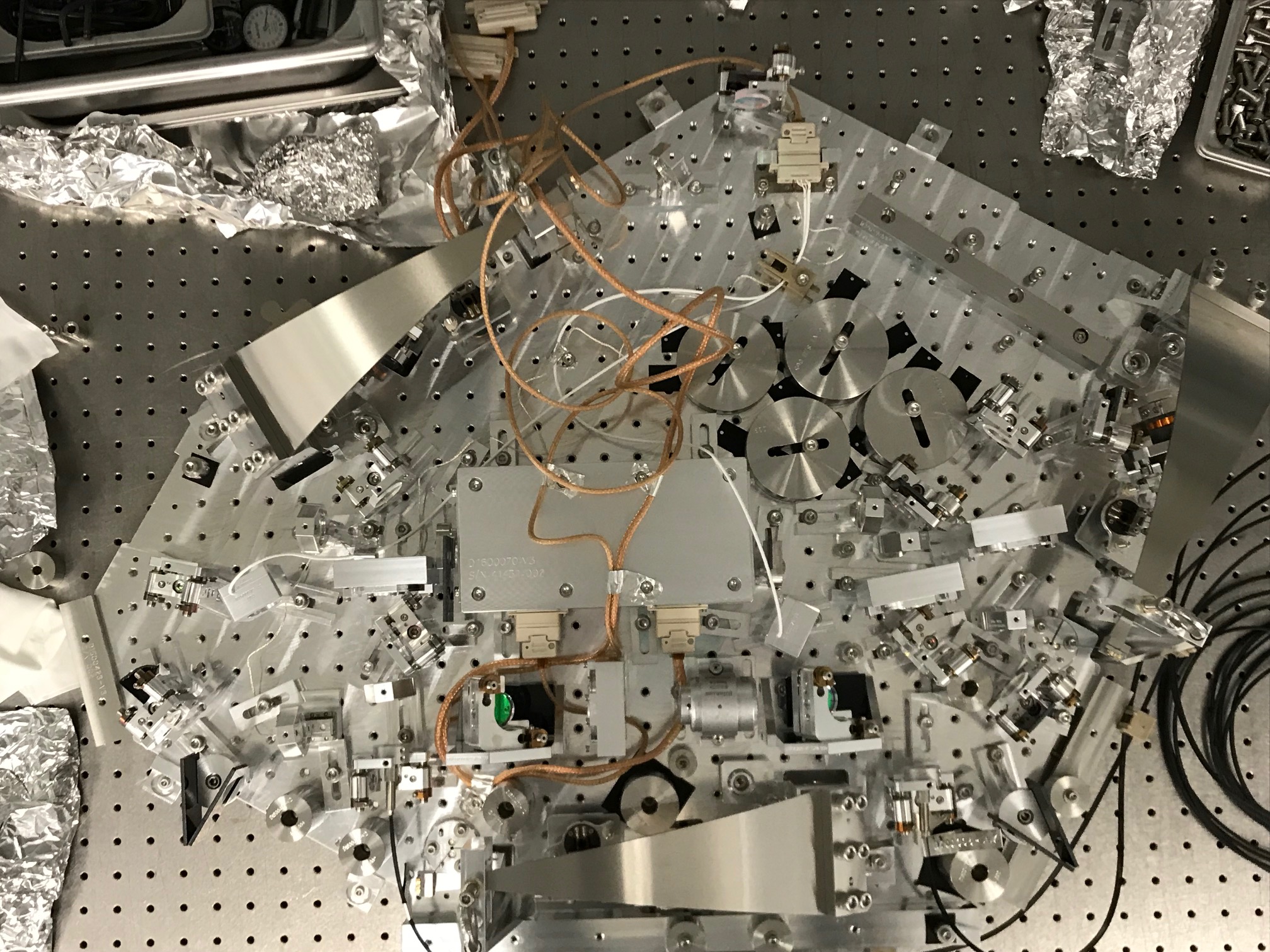
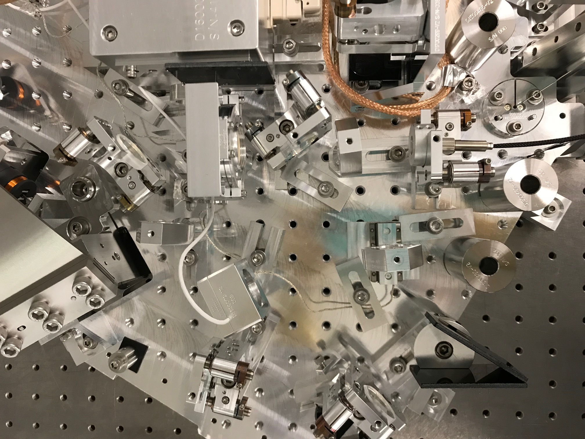
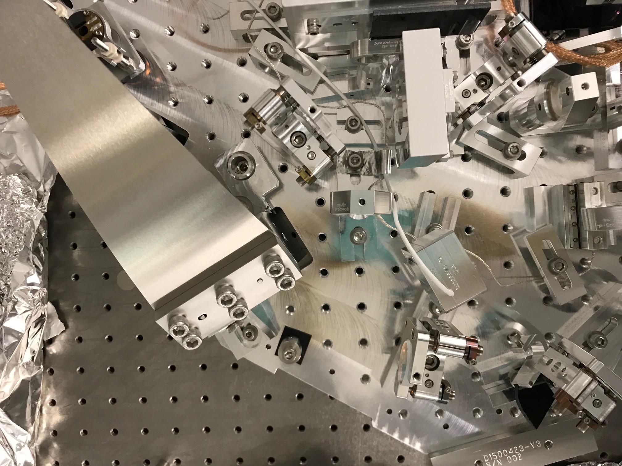
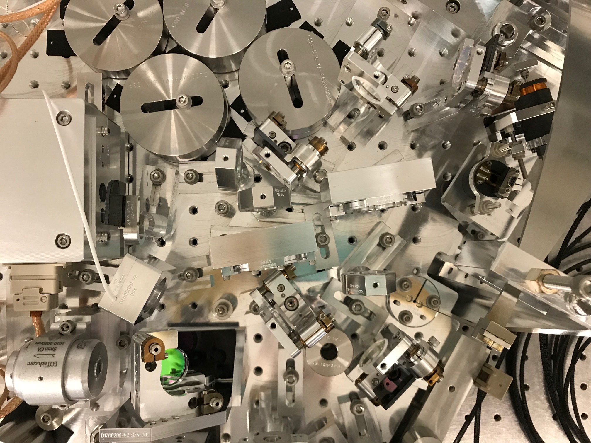
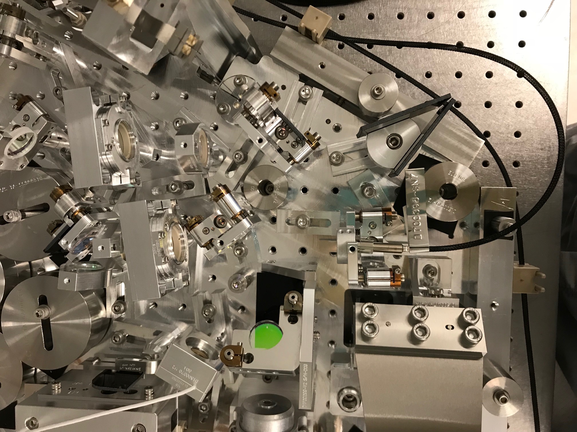
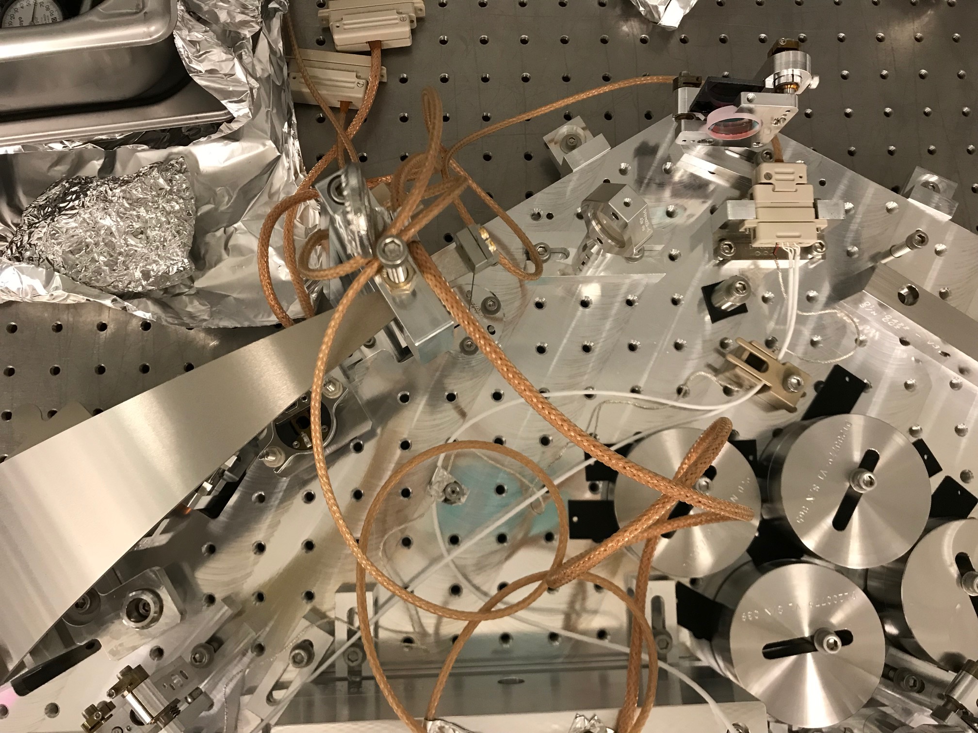
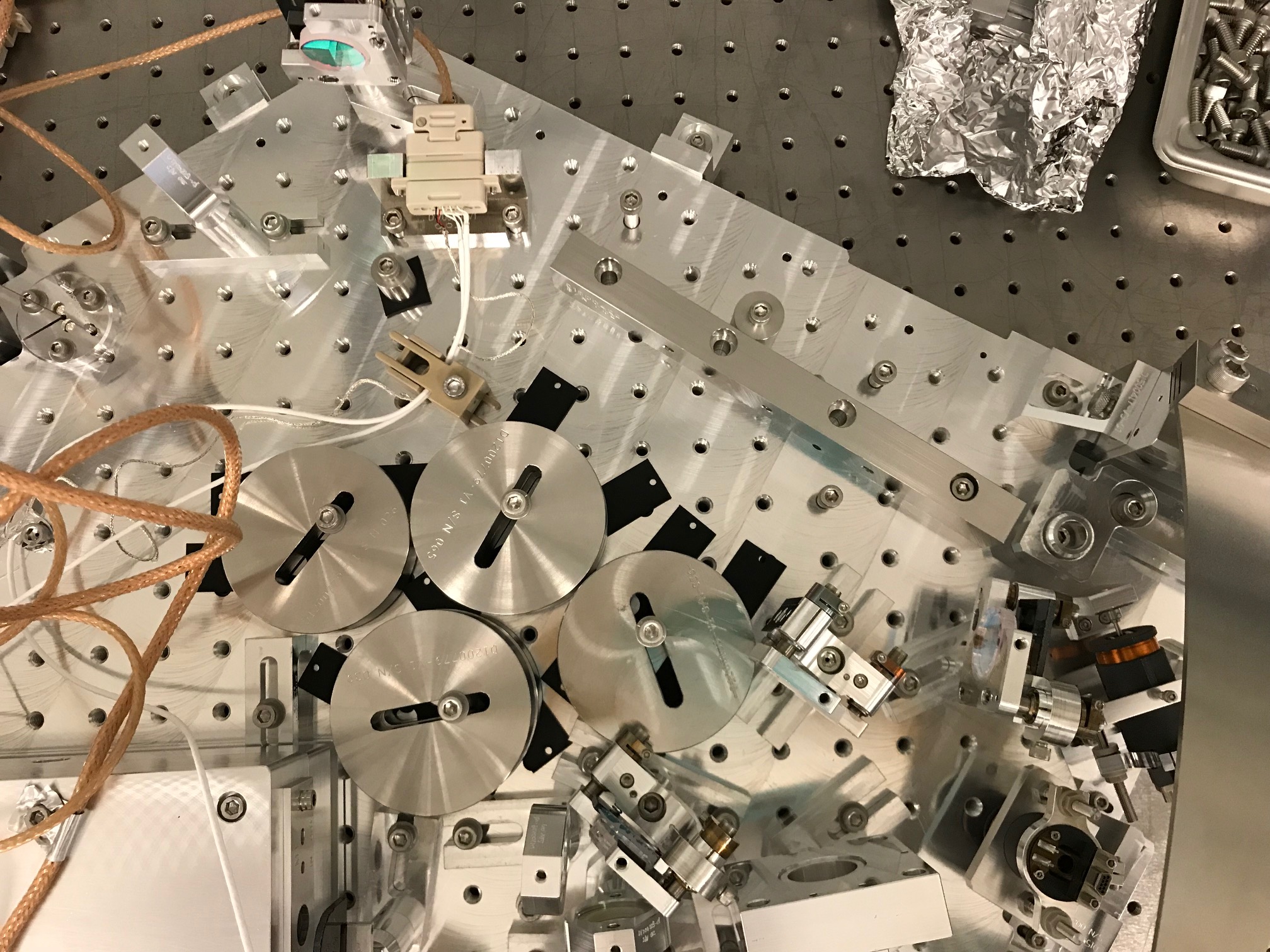
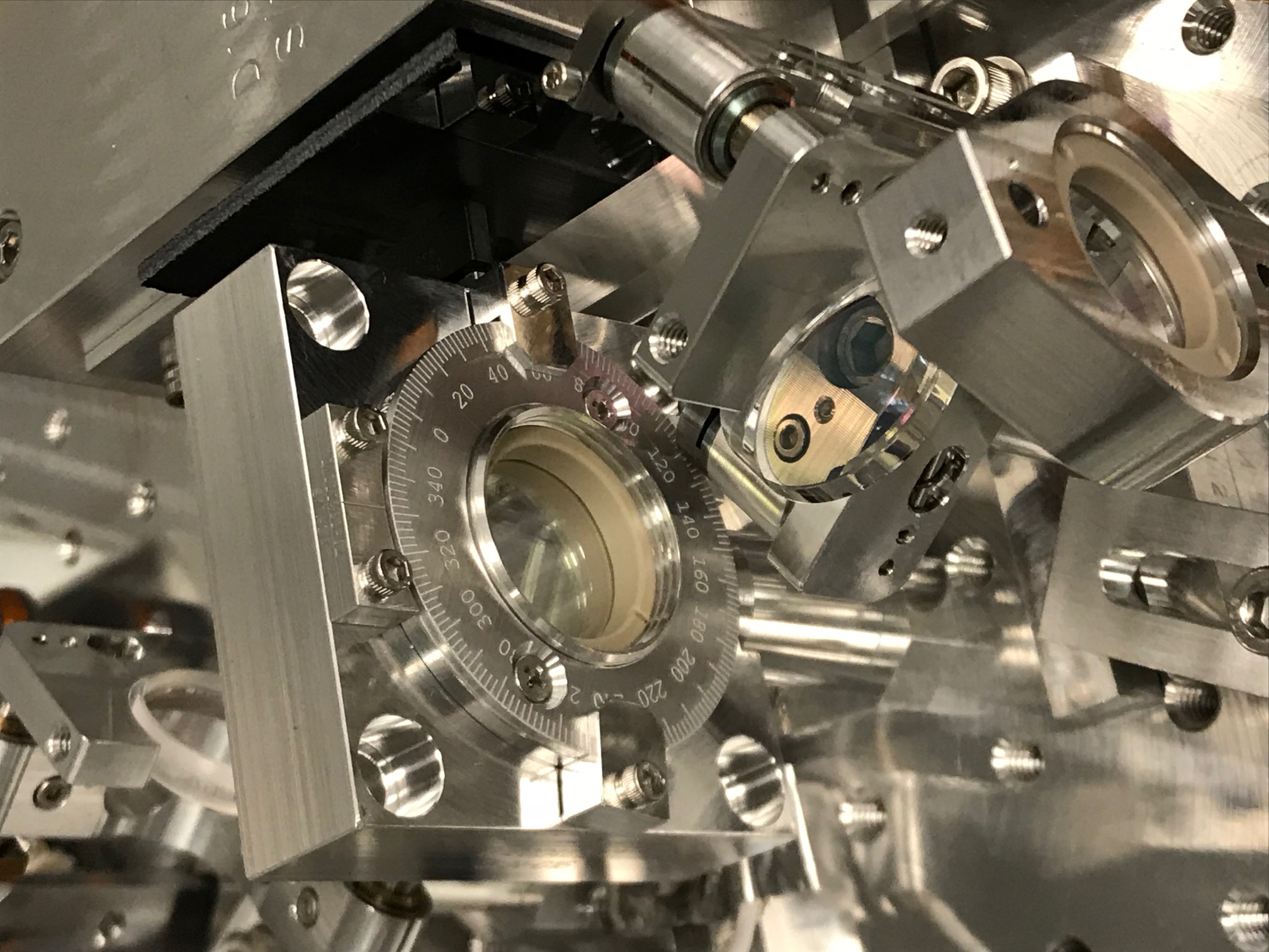
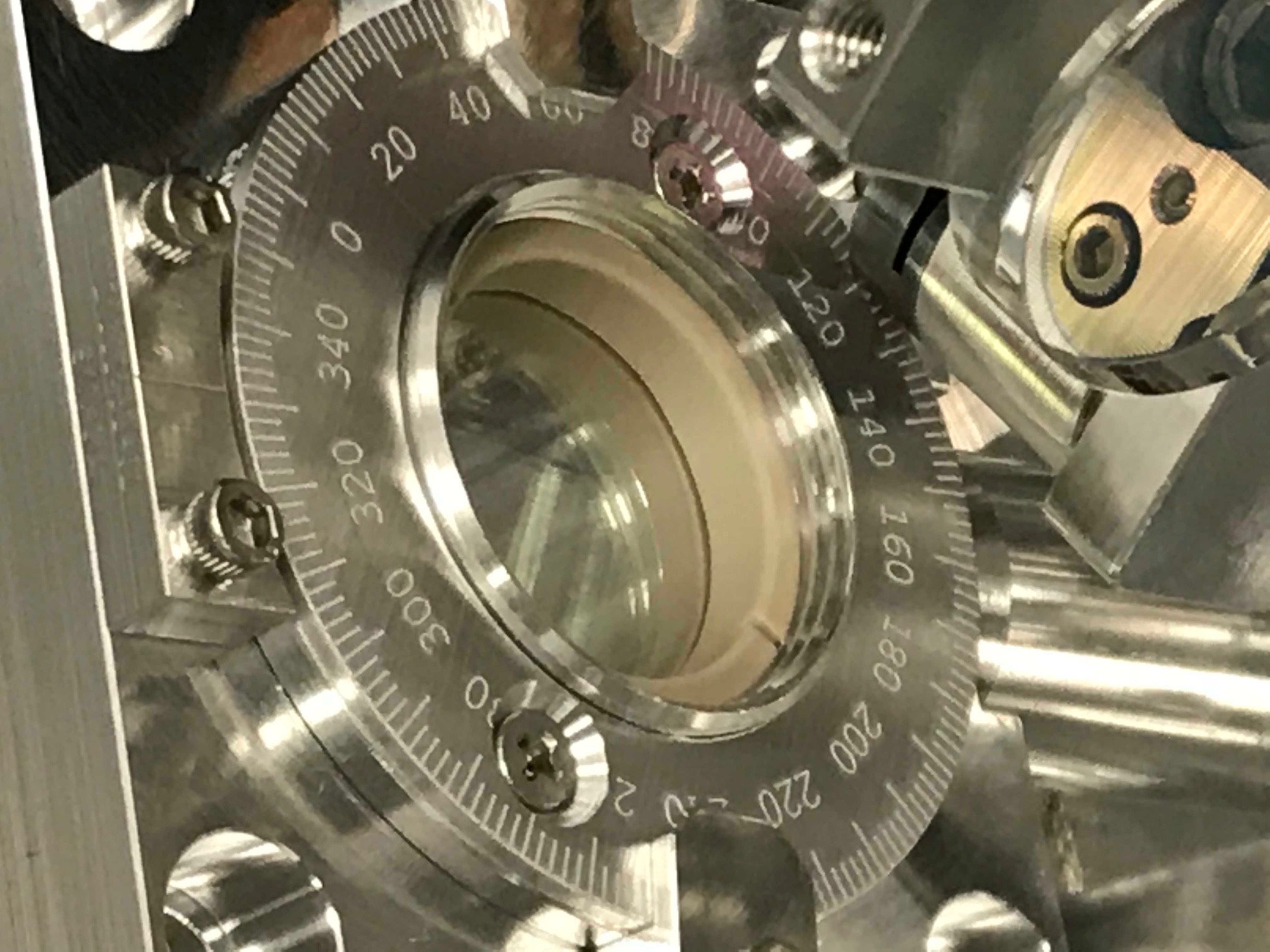
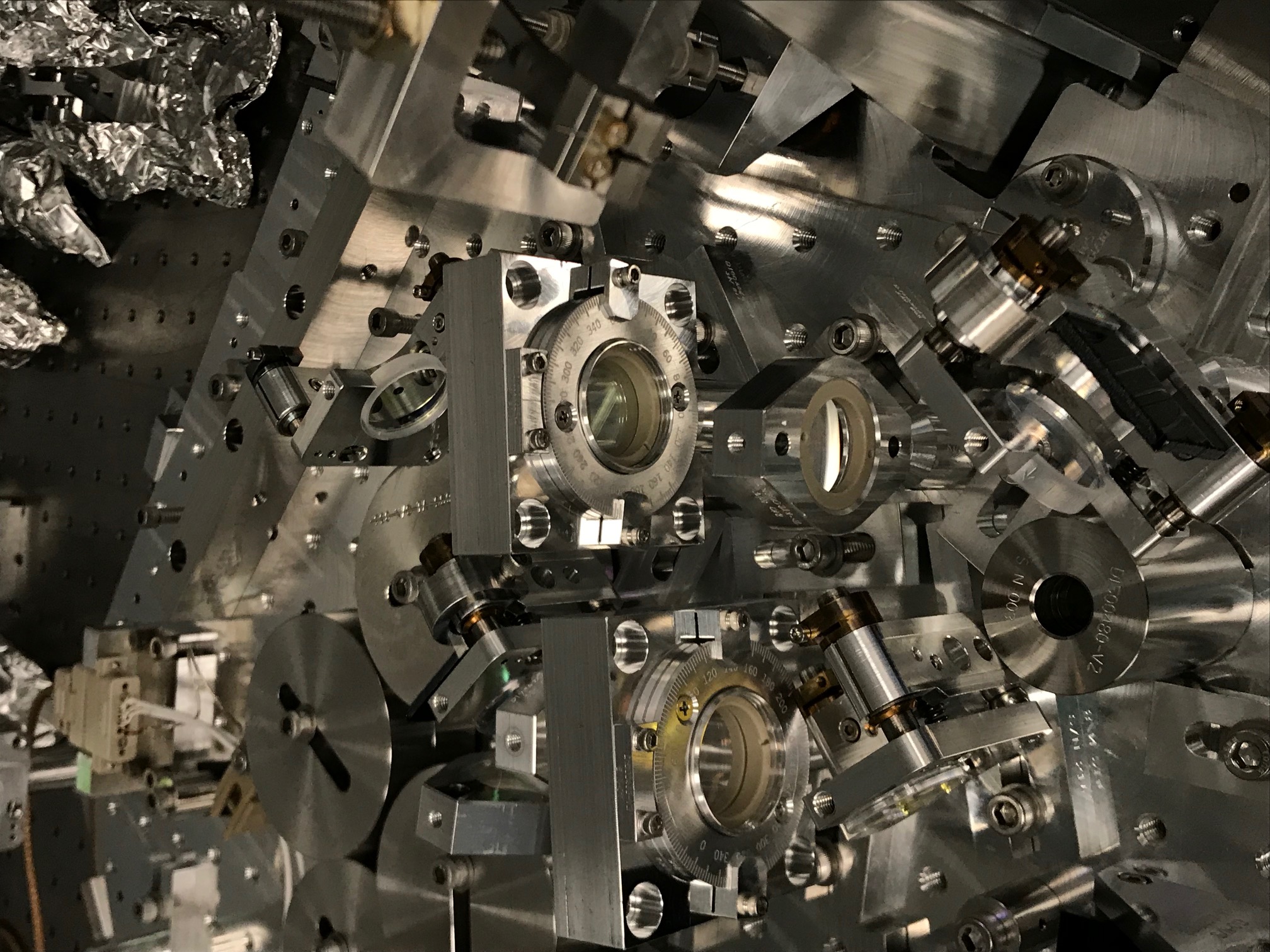
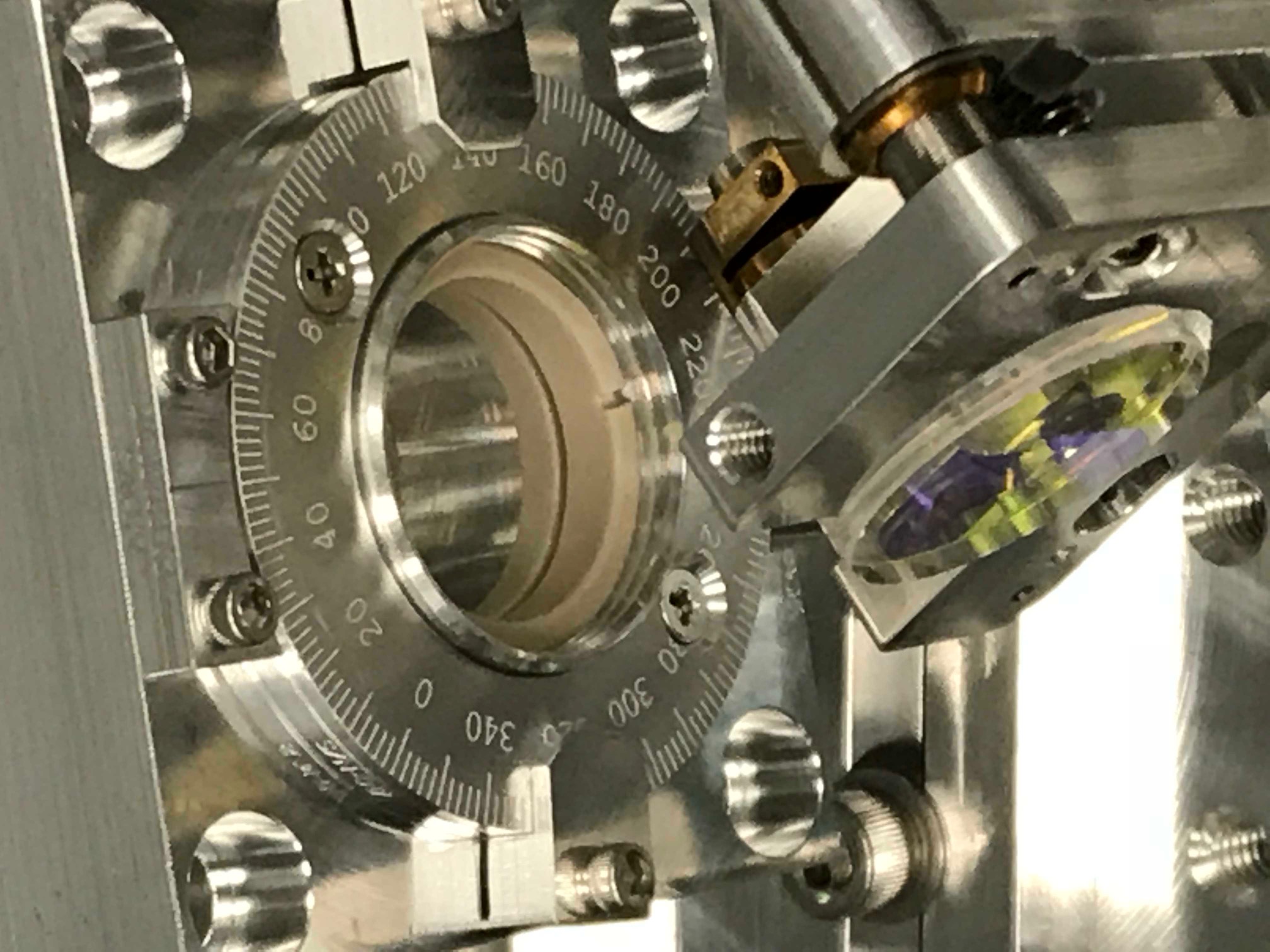
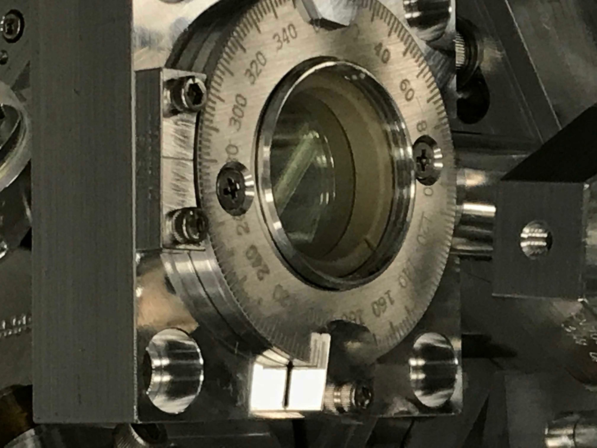
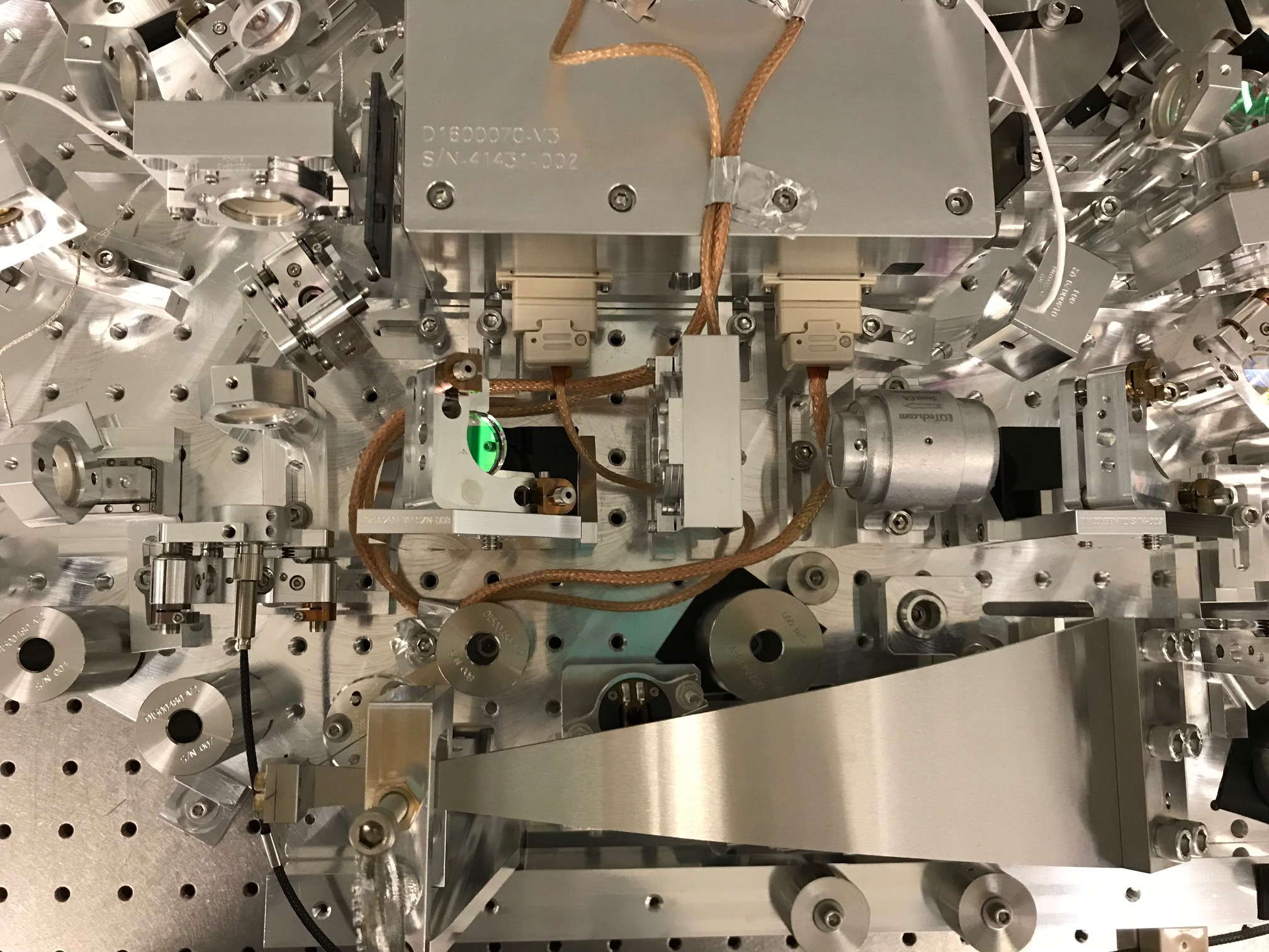
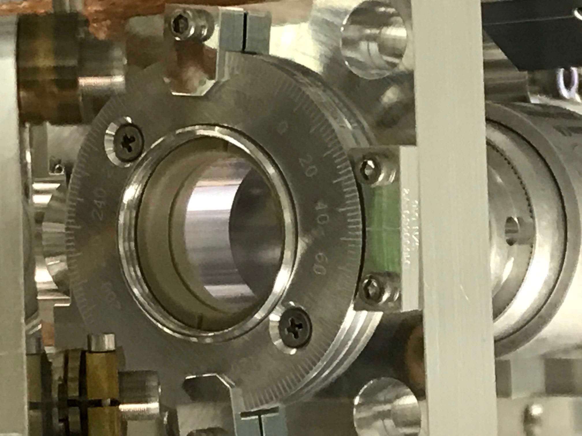
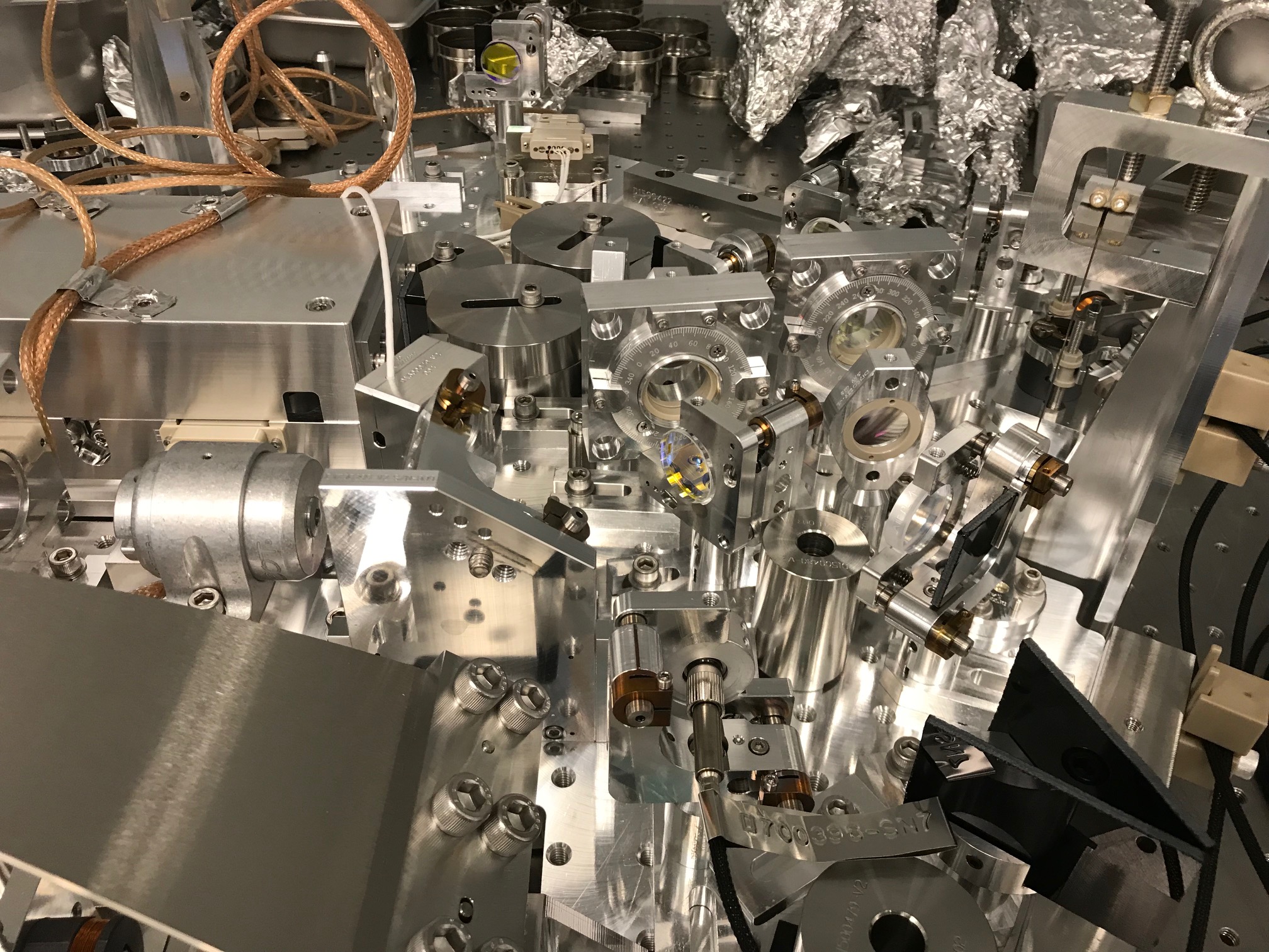
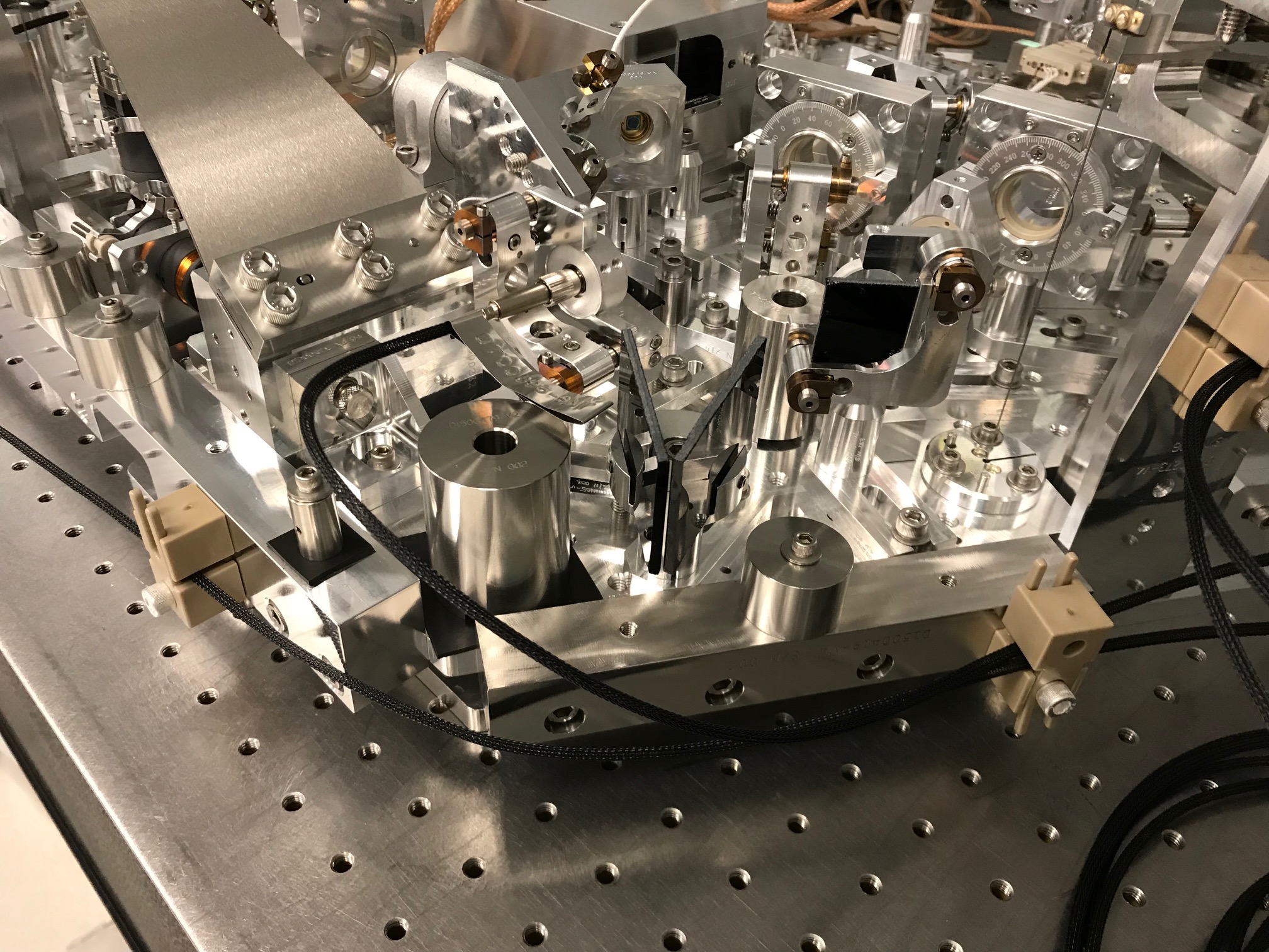
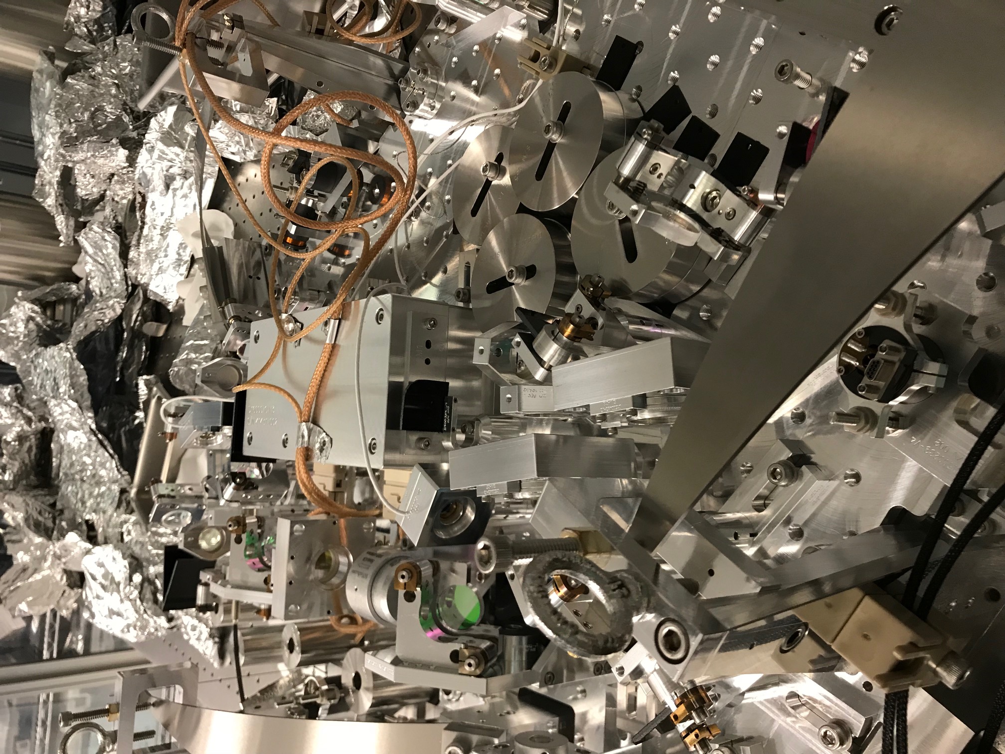
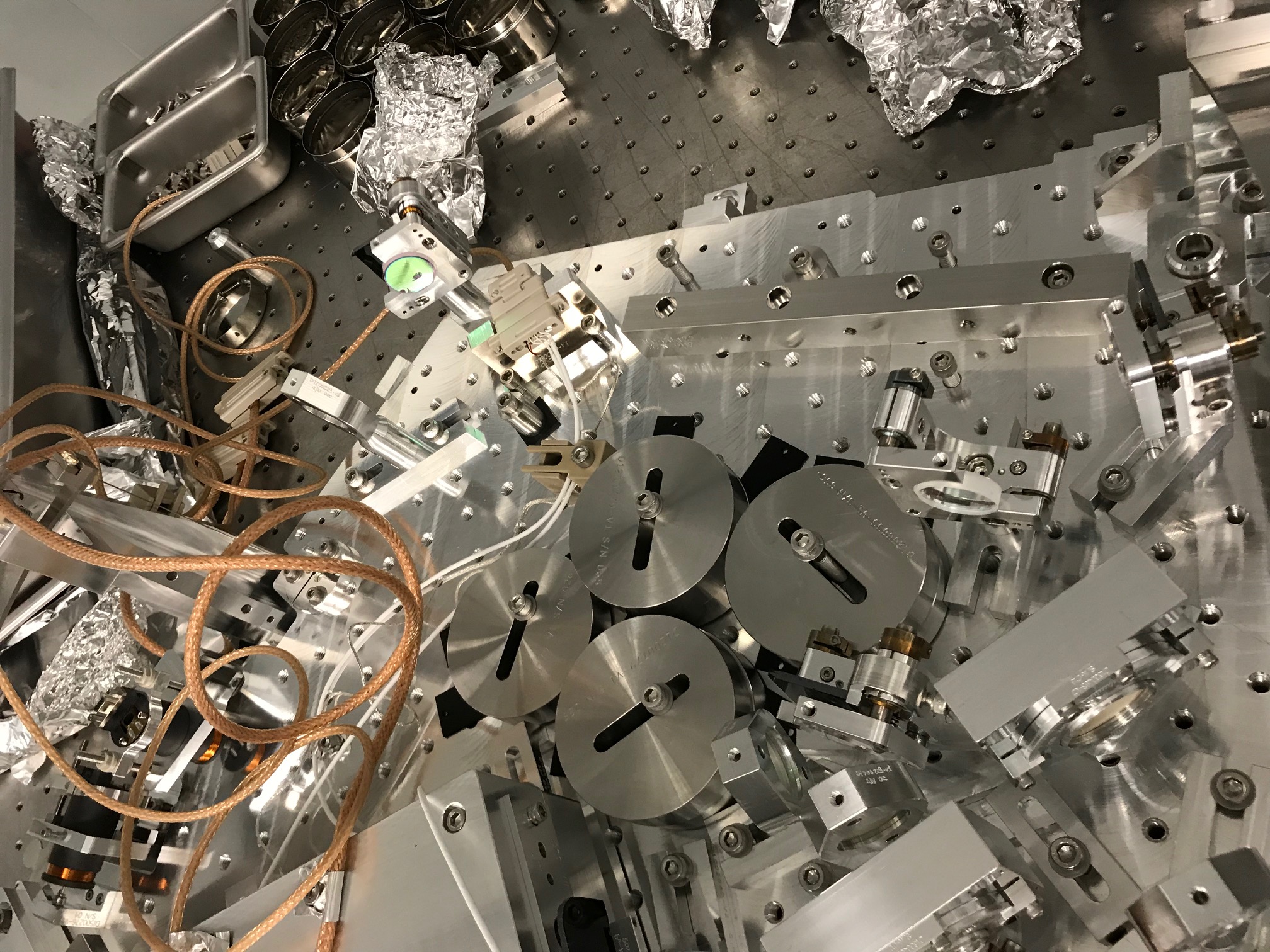
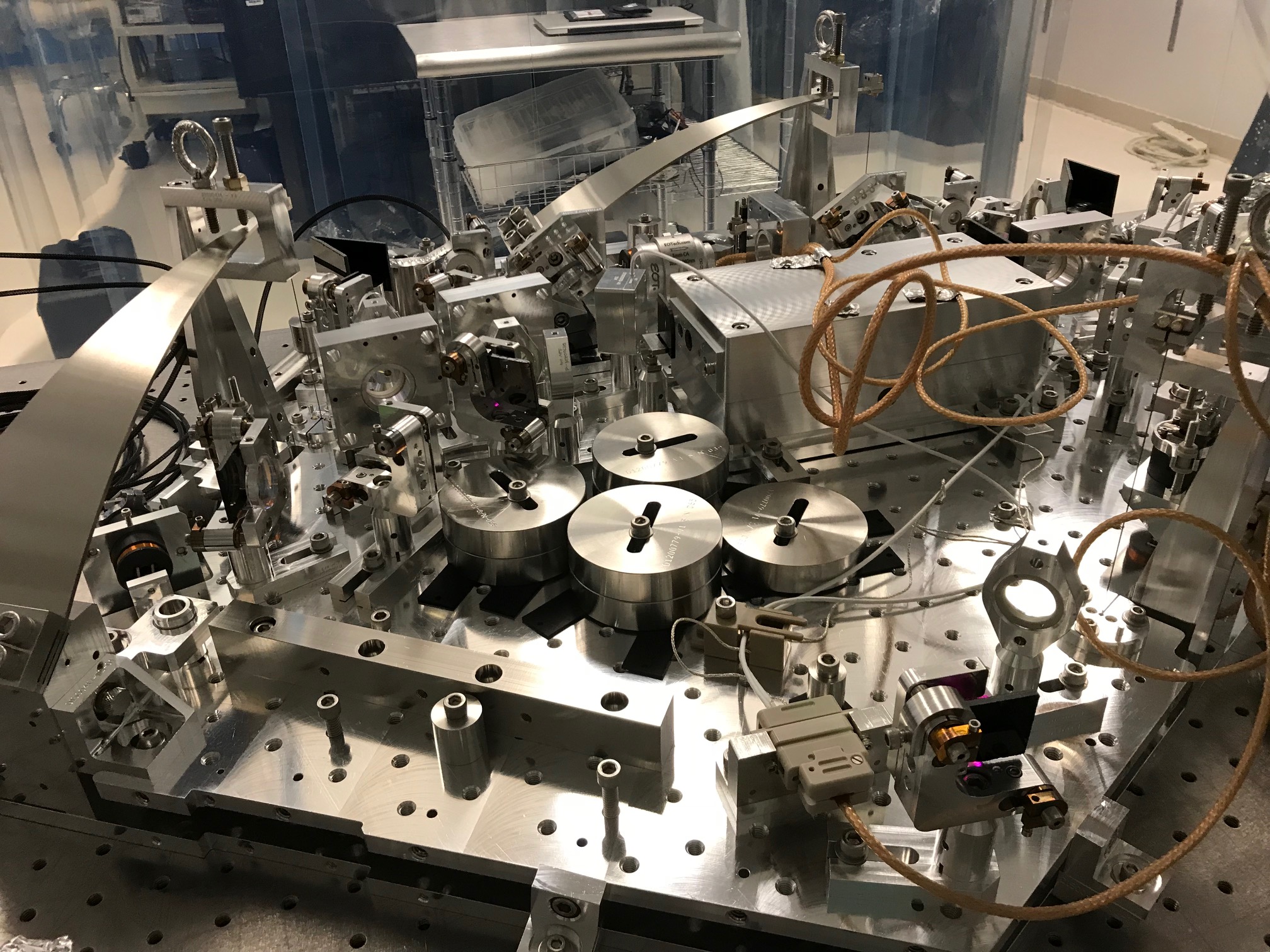
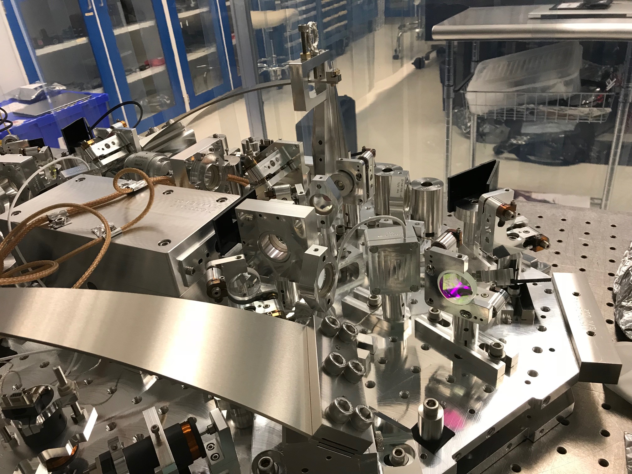
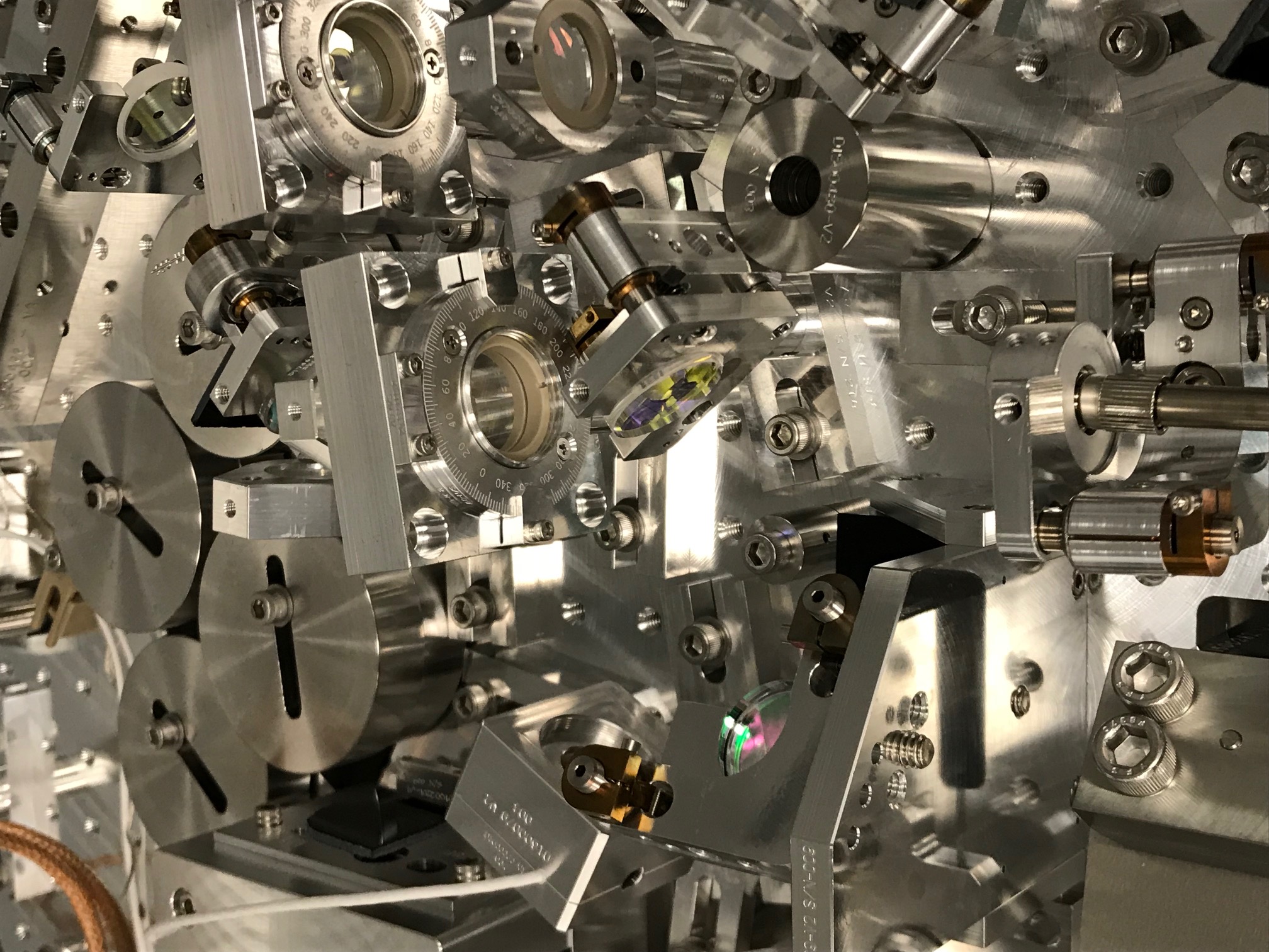
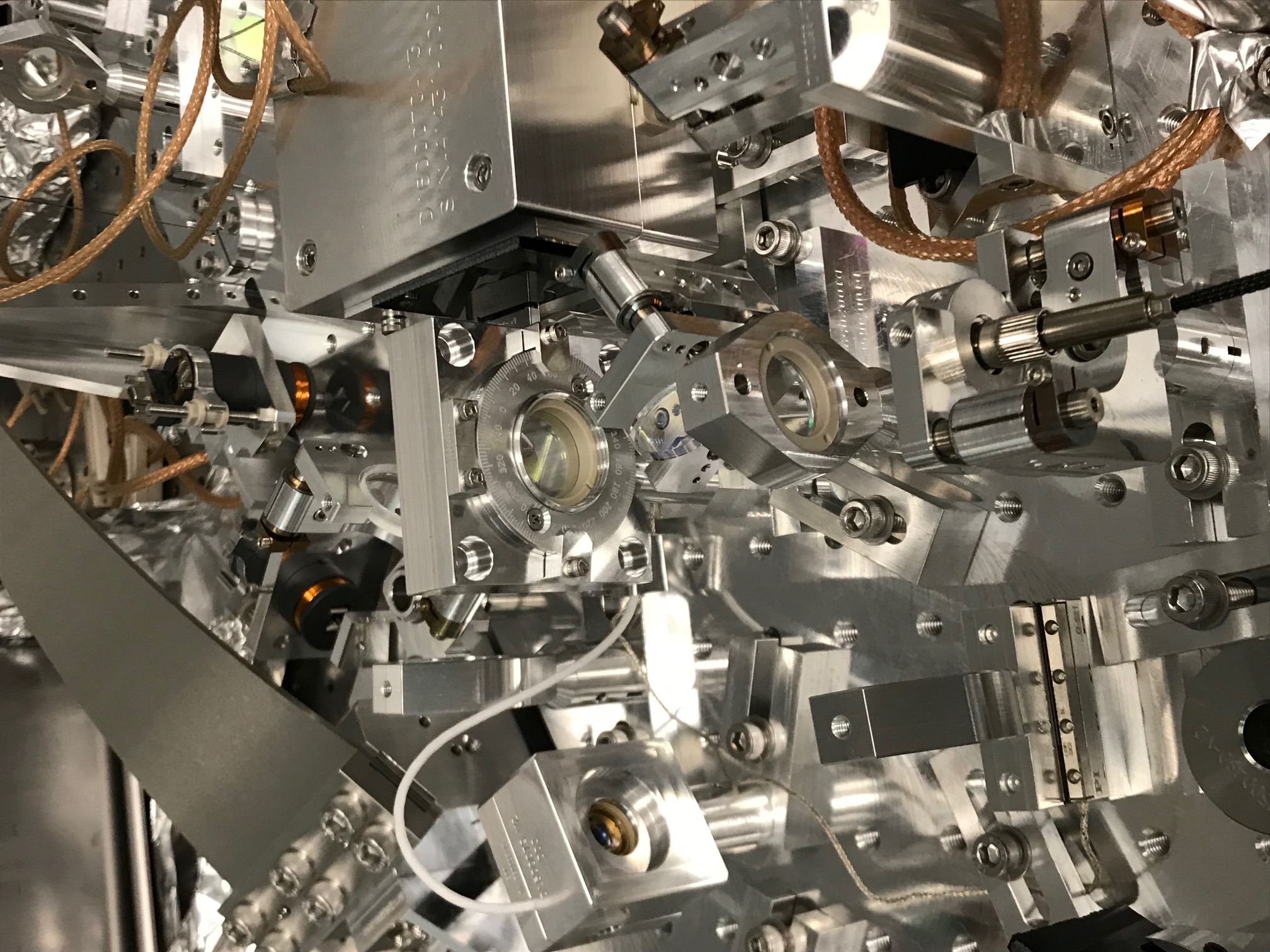
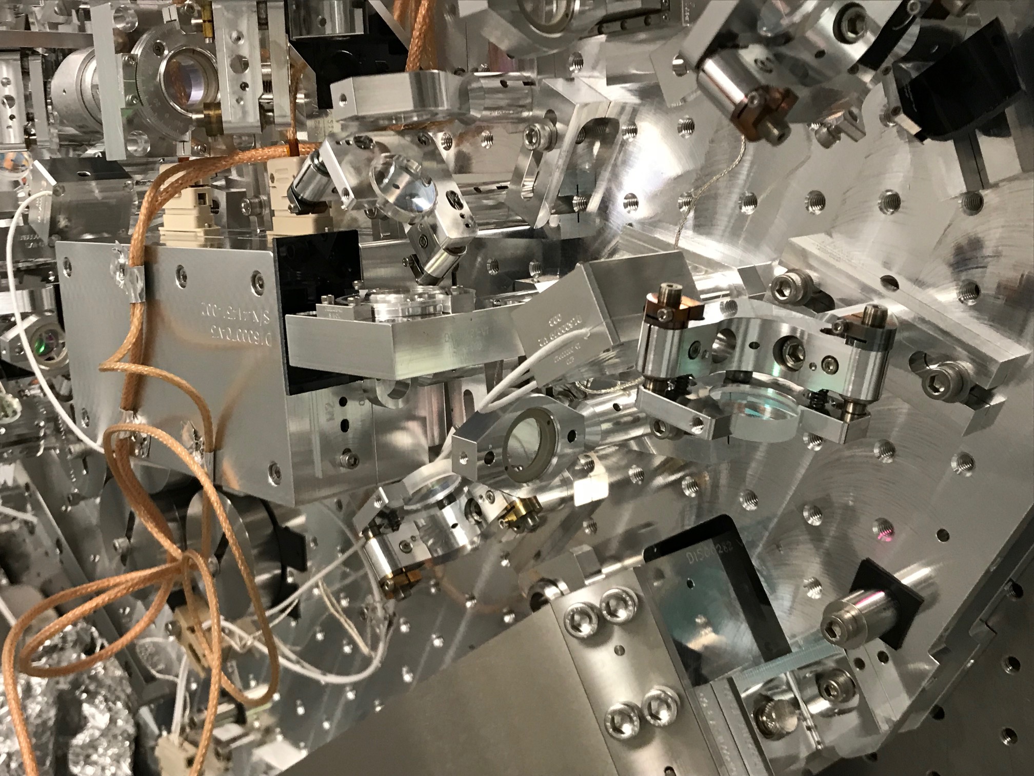
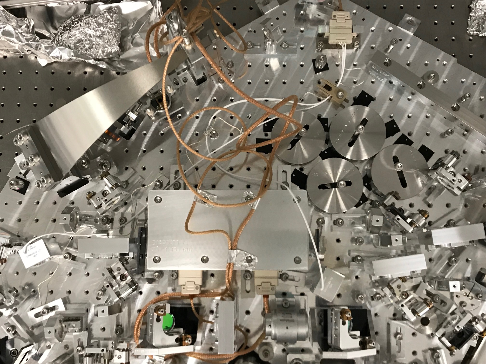
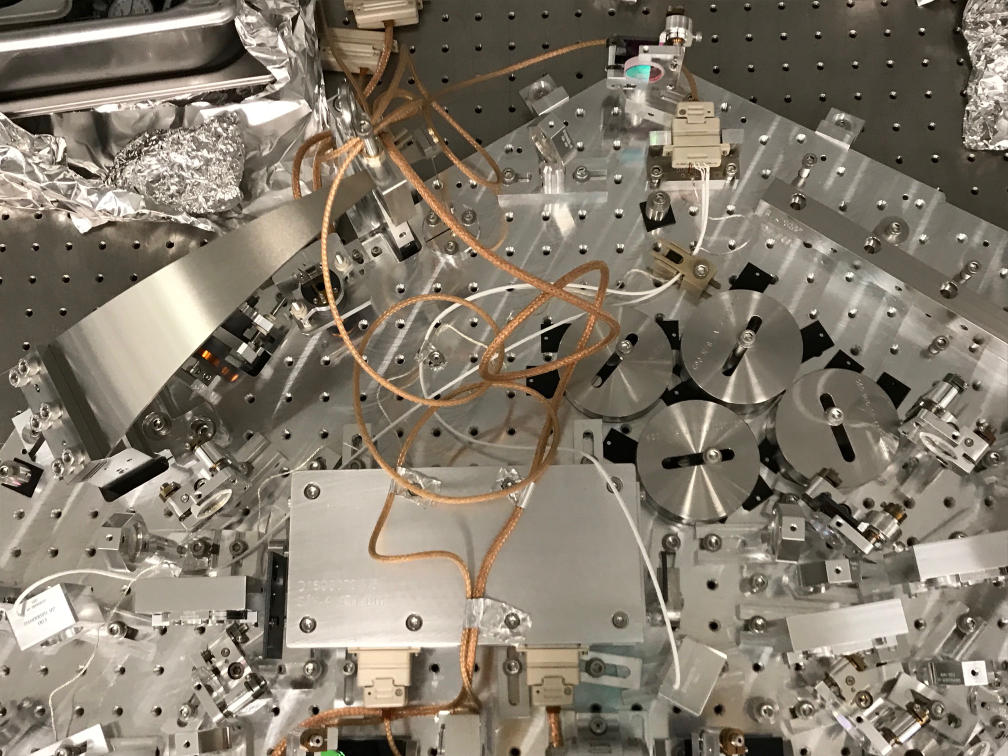
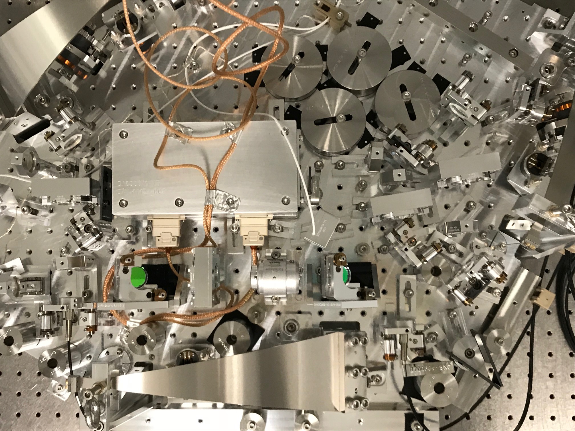
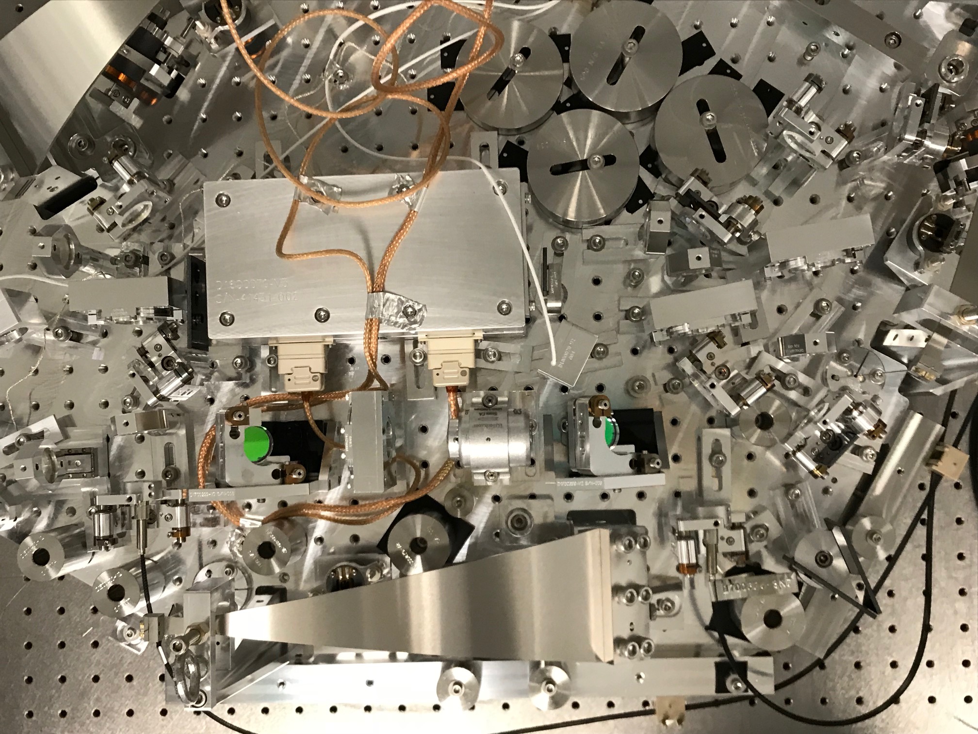
I've attached some photos of the VIP after Alvaro and TJ added cables and balanced it. I tried to give names to the photos that I think are most useful, including ones that show the settings on the waveplate rotation stages.
The CLF and green pump path waveplates were set to minimize the appearance of modes from horizontally polarized light in OPO scans. The one at the input to the Faraday isolator was set to maximize transmission of the IR through the OPO to the output of the Faraday, and the waveplate directly after the Faraday rotator was set to maximize transmission using the beam used to test the Faraday.