jeffrey.kissel@LIGO.ORG - posted 16:08, Tuesday 27 February 2018 (40749)
H1 SUS OPO Update: H1 H2 OSEMs re-cabled, Breadoard Balanced, OSEMs Centered, First Driven TFs
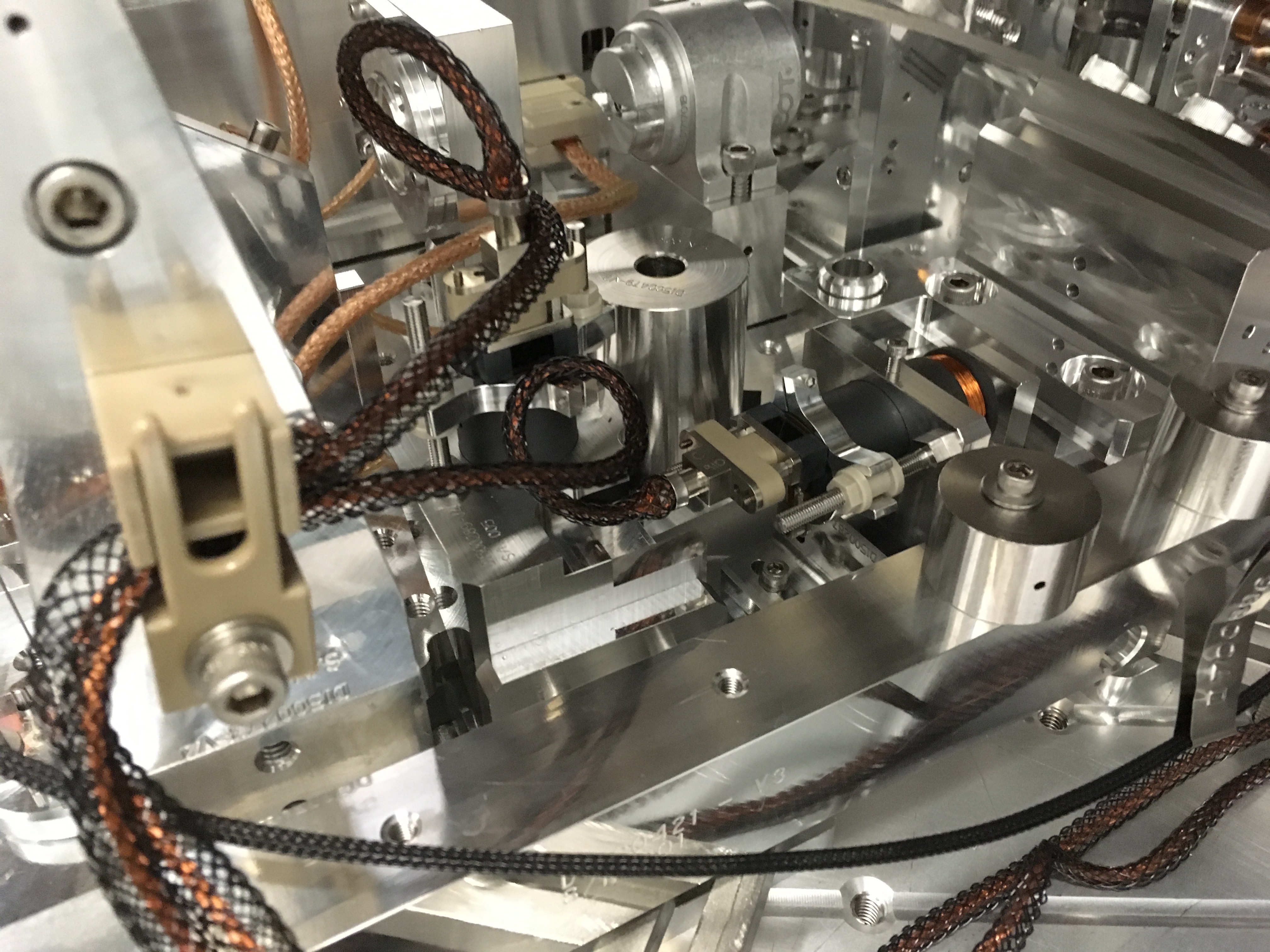
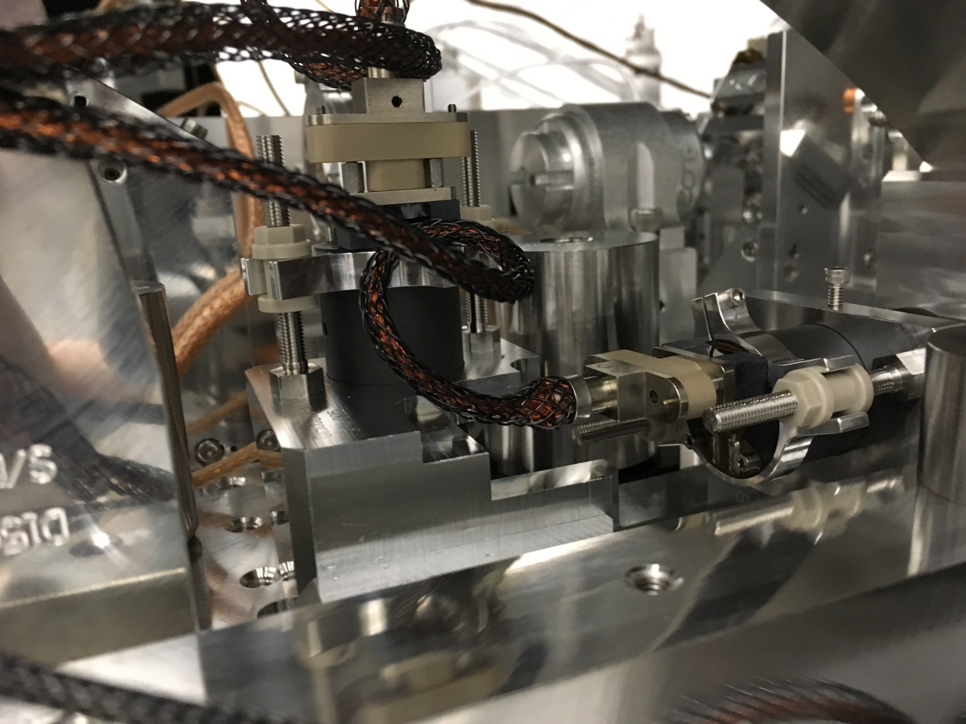
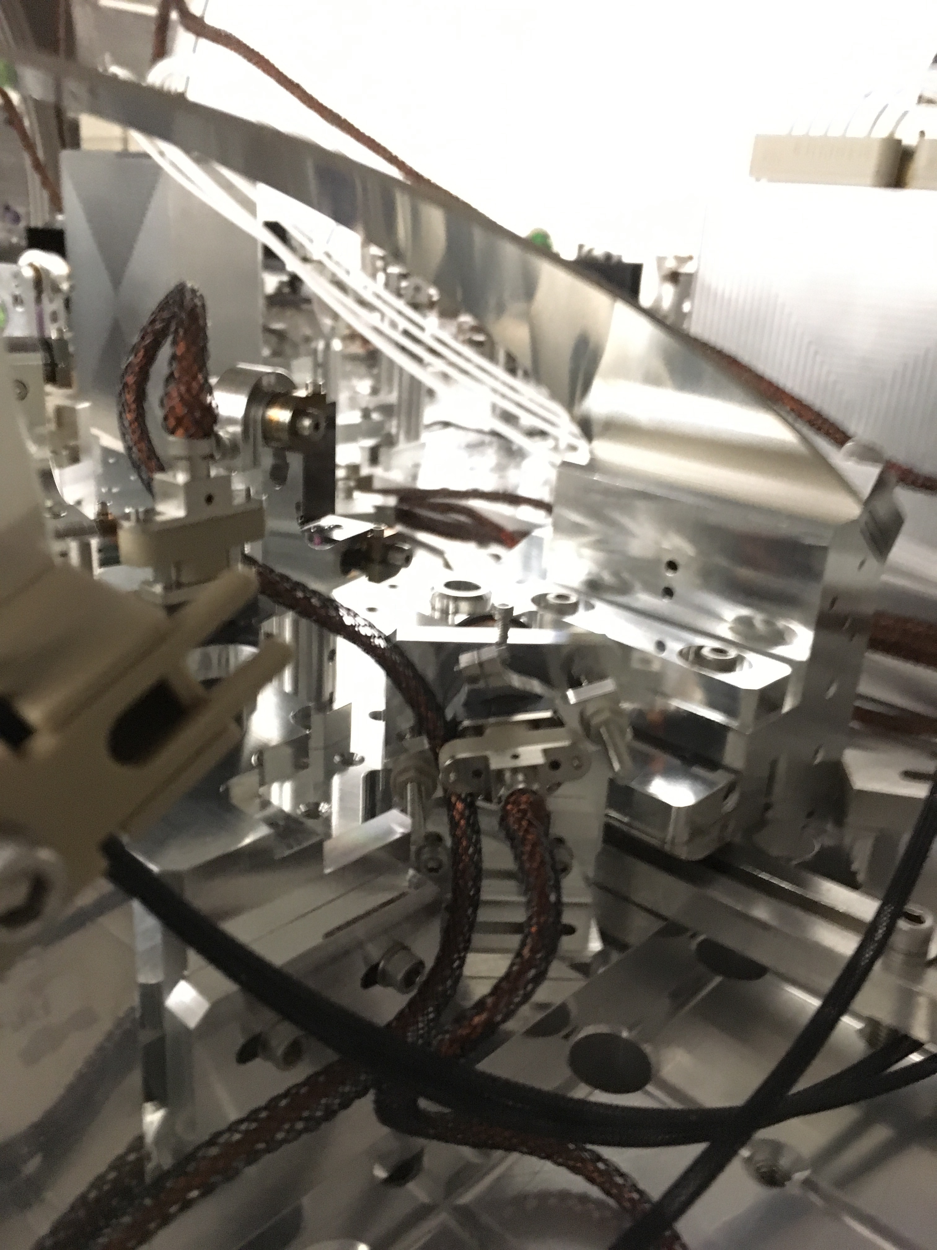
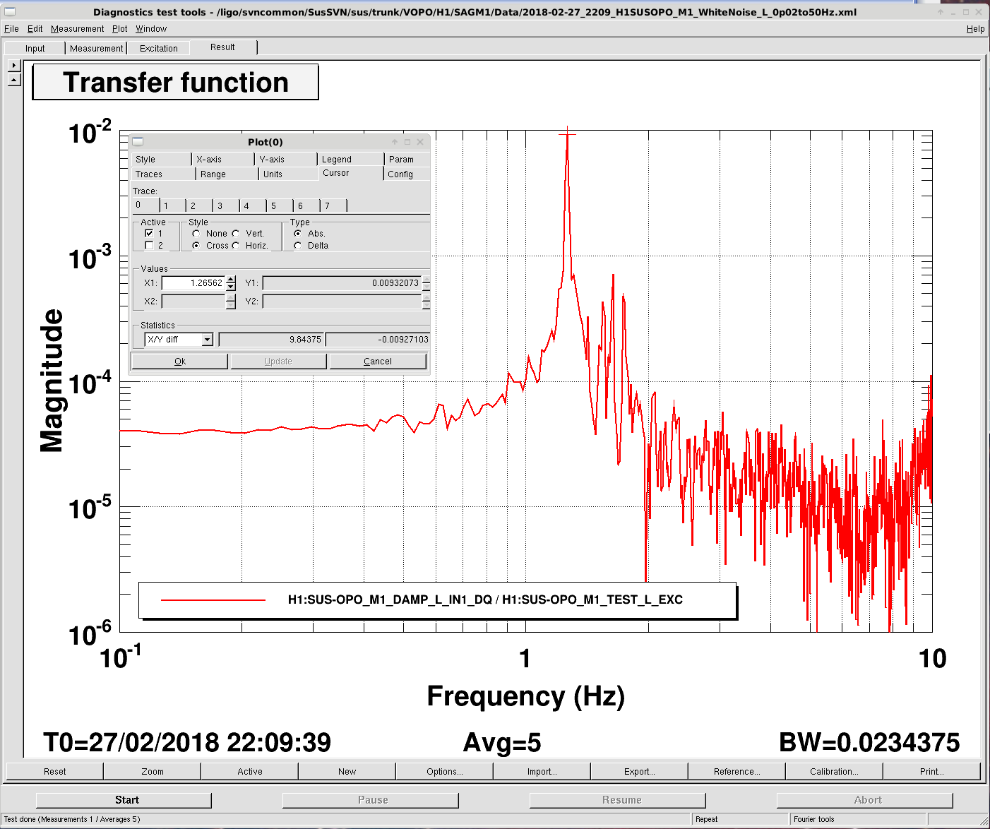
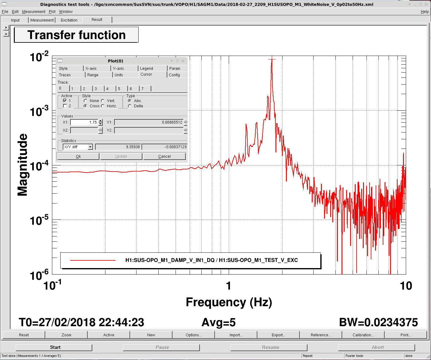
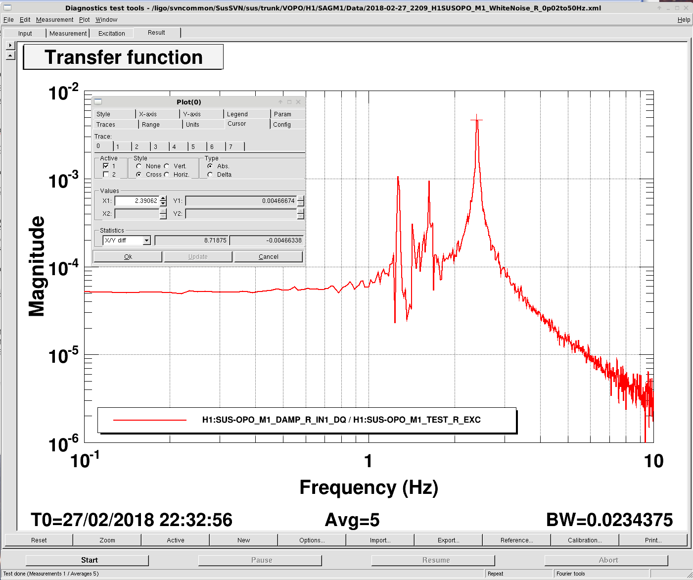
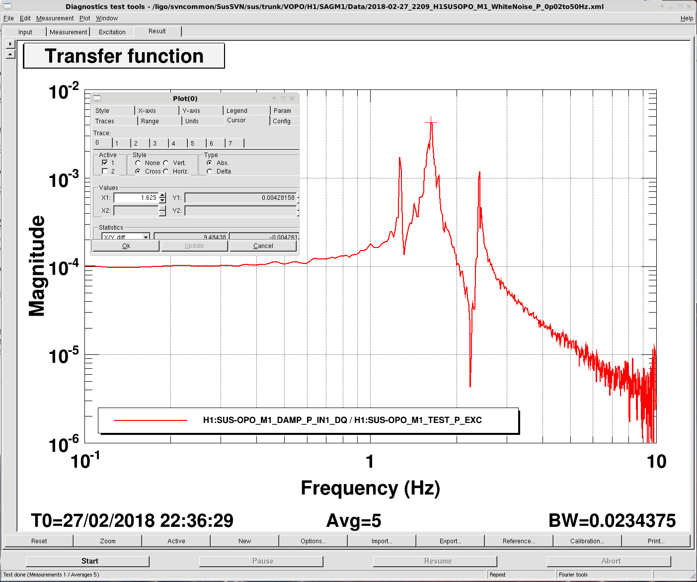
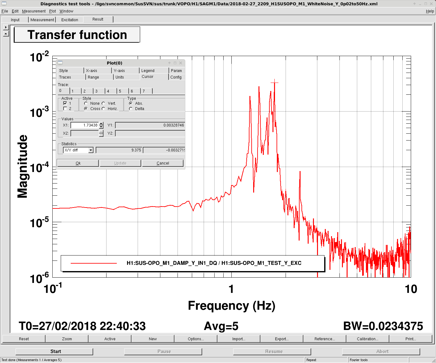
Á. Fernández-Galiana, J. Kissel

Lots of work today culminating in a fully floating OPOS and functional control system. Details summarized below!

First: Álvaro and I  remedied the H1 / H2 OSEM in-vacuum cabling issue that resulted in non-conformance to design identified yesterday (LHO aLOG 40727). We've done so at the OSEM, so there was no need to modify the front-end code.
    Attached are a few pictures of the H1 (1st and 2nd picture attachments) and H2 (3rd picture attachment) OSEMs before we recabled, showing the directional kinks that Álvaro thought could not be remedied.  The "problem:" Álvaro didn't realize how robust the OSEM cabling is, only having the optical fibers as his primary reference of in-vacuum cabling. Not a problem! Aside from the pain of unscrewing the tiny backshell screws, we merely swapped the cables, massaged them around a bit to relieve the "burned in" stiff kinks, and cable tied them into a better configuration.

Thus, all of H1 SUS OPO's OSEM signal chains now conform to the OPOS wiring found in (redlined version of) the squeezer wiring diagram (D1700384).

Second: We released the stops and balanced the table. Semi-surprisingly, we needed to add ~100 [grams] of mass to the table in order to bring the blades back to floating. We suspect this due to the temperature difference between the optics lab and installed in the chamber -- probably ~5-10 [deg C] cooler in the chamber.

Third: we adjusted the horizontal motion limiter brackets beneath the blades (see "Blade Assembly D1500293) to be centered around the horizontal motion limiter pins on the breadboard (itme 6 in D1500292), and ensured all cables were neatly arranged and free from rubbing the suspended bench.

Fourth: once mechanically free, we centered the OSEMs to the new equilibrium position. Because of the proximity to a large balance mass and the V1 OSEM, centering the H1 OSEM is miserable (i.e. using the PEEK nuts to expand or contract the OSEM sensor/coil w.r.t. to the flag/magnet). We had the most success by temporarily removing the balance mass, turning the nut, replacing it, checking the centering, then rinse and repeat until happy.

This completed our in-chamber, mechanical work for the morning.

In the afternoon, we found the need to make several changes to the control system:
    - Identified that my naive copy-and-paste of the OSEM2EUL and EUL2OSEM matrices (see LHO aLOG 40427) was wrong. Álvaro schooled me in a bit of linear algebra, updated the center of mass of the OPOS from his solidworks rendering, and re-calculated the matrix given the new order of OSEM inputs. The new version of the matrix generation can (at the moment) be found in
        /ligo/svncommon/SusSVN/sus/trunk/VOPO/Common/MatlabTools/AOSEM_Basis_2.m
    - Found that we had yet to install the updated naming convention for the OPOS in the h1susauxh56 computer for coil driver monitor signals, so we installed and restarted that.
    - Found that the OVERVIEW medm screen had a few mis-named channels that made Yaw show up instead of Transverse. This has been fixed. In the process, I've increased the visible precision of the EPICs records to reduce small-numbers vs. actually zero confusion.

Finally -- with the control system finally functional, we drove the suspension to confirm free dynamics.
We see a lot of cross-coupling between degrees of freedom that -- although resonant frequencies check out -- seem to be a little excessive. But, the chamber's pretty noisey, the ISI isn't yet floating, I haven't yet compared against a model, so maybe it's normal. I've found some L1 SUS OPO transfer functions in the SusSVN, but they look MUCH more diagonal.
However, this is enough information to design some suitable damping loops.
Images attached to this report