J. Oberling, C. Vorvick, E. Merilh, P. King, J. Bartlett
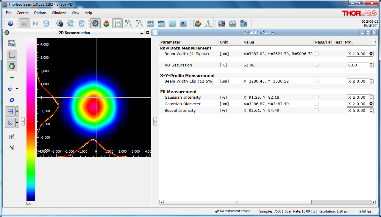
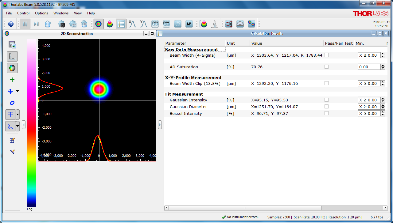
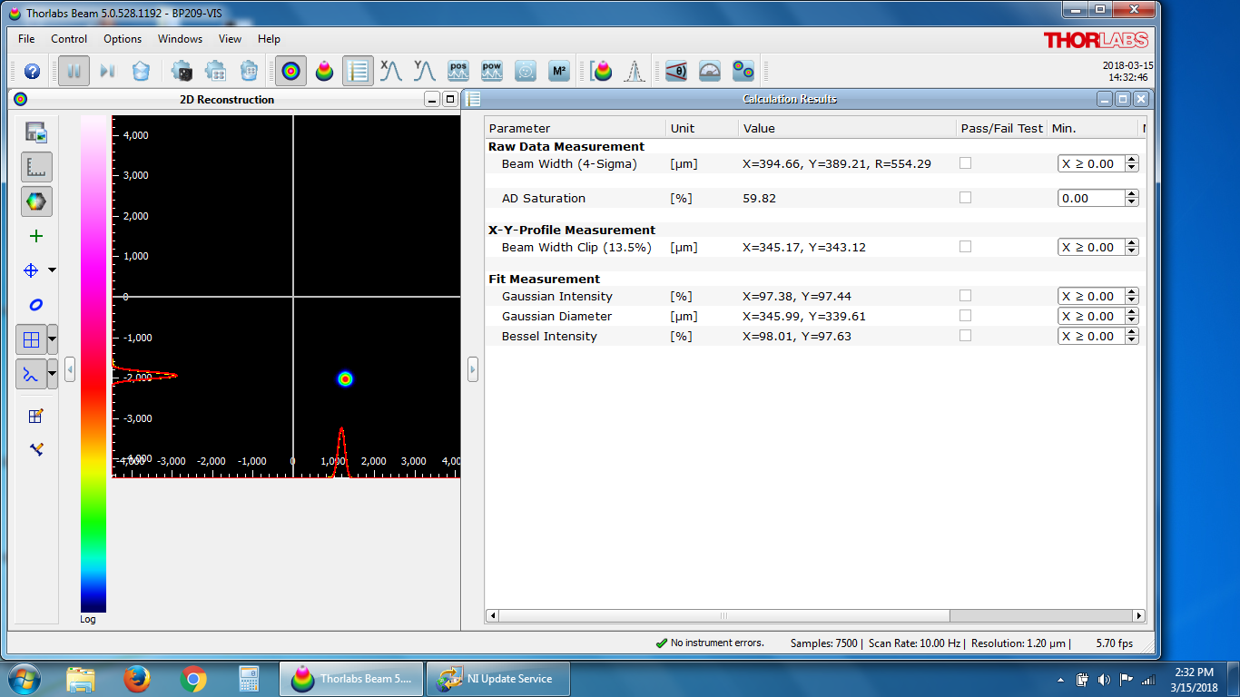
Mode matching, mode matching, and more mode matching. We began Monday by installing the mode matching solution detailed in the previous alog, and then attempting to optimize it to get close to the desired waist for the 70W amp. Unfortunately, as is the case with most 1st attempts at mode matching, this didn't get us where we needed to be; the smallest we could get the beam was ~450 µm in diameter, a bit off of the required 273 µm diameter. At this point, Cheryl volunteered to lend us her experience in mode matching, which I accepted (thank you Cheryl!). So on Tuesday morning, Cheryl and I went into the enclosure to tweak up the mode matching. She took accurate measurements of the lens positions and we re-measured the waist; in addition we looked at the previous measurement Ed and I took of the FE beam to assess beam quality (done with the Wincam), and we took a new one with the Thorlabs beam profiler after the mode matching lenses (1st attachment). As them beam looked like it had some lobes on it (which was not different than the older Wincam image), we then looked at the beam path from the NPRO to the MOPA inside the 35W FE to see if there was anything that could be causing it. We found that the beam alignment through the extra AOM inside the FE was off, as well as some very slight clipping on the razor blade dump meant to block the 1st order diffraction from said AOM (if it was being utilized, which it is not). We also took a look at the beam profile of the NPRO using the Thorlabs beam profiler (2nd attachment), and didn't see anything that looked amiss. We decided to move on with optimizing the mode matching, so Cheryl took the lens position and waist measurements and plugged them into A La Mode (Matlab mode matching script), which told us how to move the mode matching lenses to optimize the output waist. We went back and forth with this for a while, getting closer, but not quite getting there. One problem we immediately noticed: the downward angle of the FE beam induced by the new pick-off was causing us problems with the lens alignment. We did not have enough adjustment range on the Owis lens mounts to center the lenses on the beam, and since these mounts were originally installed on fixed-height pedestals, the small amount of adjustment range from the mount was all we had. We decided to call it a day and continue on Wednesday morning. That evening, Cheryl dug into A La Mode to work on a robust mode matching solution. Her results were to use the same lenses (f1 = -50mm, f2 = 80mm), but move the position to +479.5mm for the 1st lens and +527.7mm for the 2nd lens (this assumes 0.0 mm is the outside edge of the 35W FE enclosure).
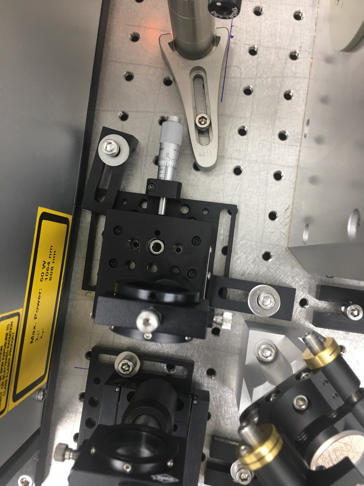
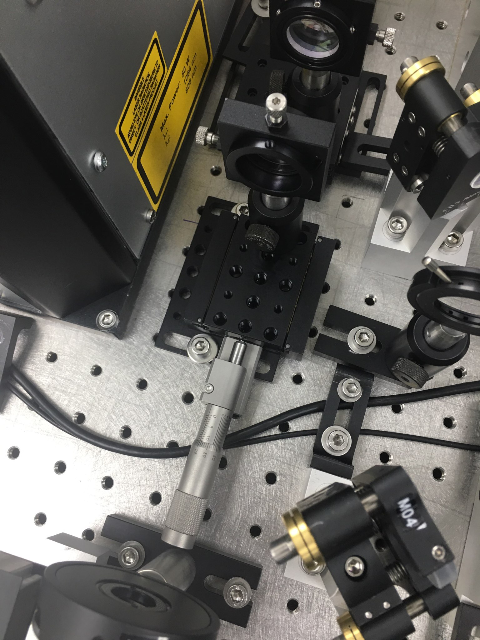
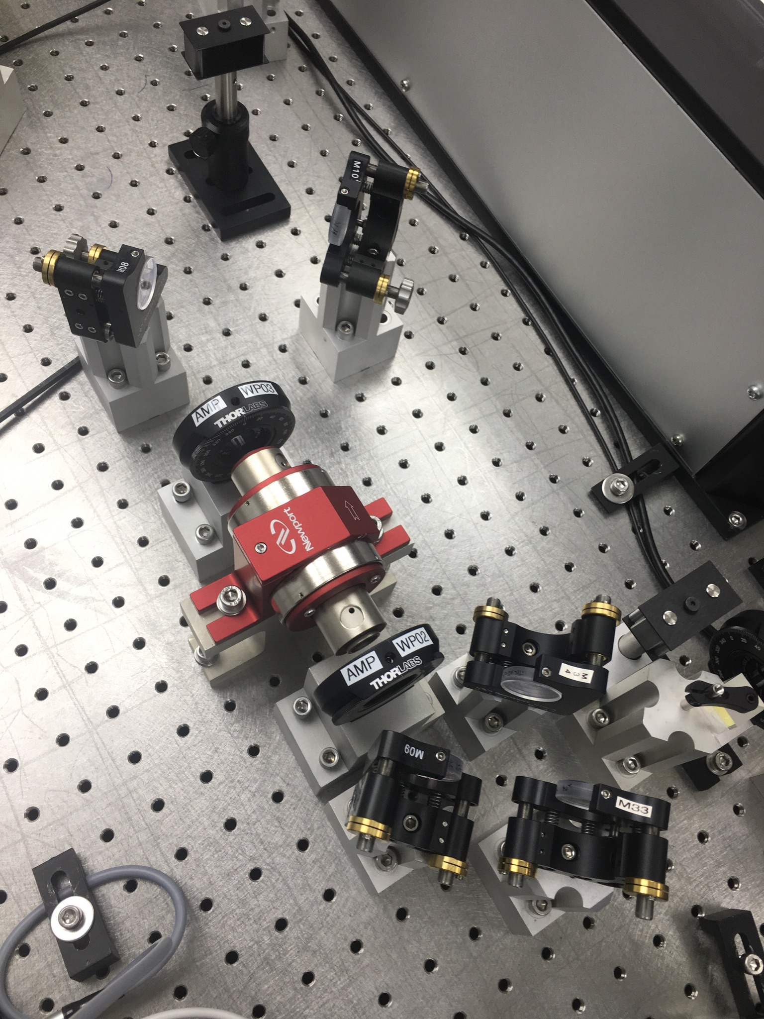
First things first on Wednesday, we had to decide what to do about the lens alignment problem. In an ideal scenario (assuming we had all the time in the world), we would painstakingly align the beam out of the FE to correct for the downward beam angle. Back in the real world however, we decided to ditch the fixed height pedestals for adjustable height. Due to the odd mounting of the Newport SDS40 translation stages, we had to ditch these as well. Eventually, we were able to come up with a workable solution that gave us the adjustments we needed to complete the mode matching; unfortunately, this took most of the day. While I was building out the new mounts, Cheryl painstakingly measured the distances to position the lenses and made fiducial marks on the table. Once the new mounts were assembled (3rd and 4th attachments), we test fit them on the table; the footprints are larger than the old fixed-height pedestals, but they fit where they need to and give us the adjustment we need. We have since found (see below) that we probably need to swap out the huge micrometer on the 2nd lens mount with a smaller one, but for now this gave us a workable solution.
On Thursday, Ed and I began fixing the above noted clipping issues in the FE. We removed the side panel and adjusted the AOM position so it was centered on the beam. We then moved the beam dump just enough to clear the slight clipping. Of course, upon turning the MOPA on, we had to slightly adjust the alignment into it to return to optimum operation. We checked the beam alignment outside of the FE and everything looked to be in the same place, so we moved onto installing the mode matching lenses. We started by installing and aligning the new lens mounts; we took care to ensure the mounts were even and aligned to the beam. We then installed the lenses, aligning after each install. After this, we set up the Thorlabs profiler and began adjusting the position of the 2nd lens. Right off the bat we had a waist of ~344 µm in diameter (5th attachment). Moving the 1st lens a small bit and readjusting the 2nd, I was unable to get the beam any smaller (moving both directions for the 1st lens produced the same results, a larger beam at our desired waist location). Cheryl had joined us by this time, and we decided that this was close enough for a rough mode match (we'll optimize the mode matching once we have the 70W amplifier installed and aligned), so we started placing the other required optics in the beam path: WP02, PBS02, AMP_WP02, AMP_FI (and associated beam dumps), AMP_WP03, and AMP_M01.
We immediately ran into a problem. Due to an interference between M04 and M33 on the original PSL layout (that oddly enough was not present at LLO, per M. Heintze), the beam out of the LHO FE was not aligned along the row of holes as indicated in the layout; it was angled towards the FE slightly. Because of this, the mount for WP02 (which assumes the beam is aligned along a row of holes), is clipping the beam. At this point I had to leave to attend a meeting, so Cheryl and Ed finished up installing the table components. The WP02 issue was resolved by changing the mount to a fixed height post and a baseplate. They put the Faraday isolator (AMP_FI) on the table and noticed immediately that the beam was clipping (once again being bit by the downward launch angle imparted on the beam by the new FE pick-off). They re-installed the dog leg after M33 so the beam height could be adjusted up and made level through AMP_FI. The final attachment shows this setup; this is simply a mock up, as M09 and M10 are to be used in the FE DBB path, and they had to shift AMP_FI laterally, which blocks the beam from the 70W amplifier. Unfortunately, given the huge micrometer on the 2nd lens mount, this is the only way to currently install this setup. So first thing tomorrow we need to hunt down a smaller micrometer for the 2nd lens mount, so the dog leg can be shifted up the table to clear the interference between AMP_FI and the resulting 70W amplifier output beam.
While all this has been going on, Peter has been working on figuring out the wiring for the new external shutter so that is ready for when we have light through the 70W amplifier. Jeff Bartlett has been working on the plumbing required to get the power meter in the new external shutter plumbed into the PSL cooling loops; this power meter will use the old HPO power meter circuit. In addition to this, Peter and Jeff dried out the old HPO Laser Head and Laser Crystal water circuits; once the new external shutter power meter has been plumbed in, the HPO Power Meter water circuit will be dried out as well, thus completing the mothball of the HPO.