J. Oberling, E. Merilh
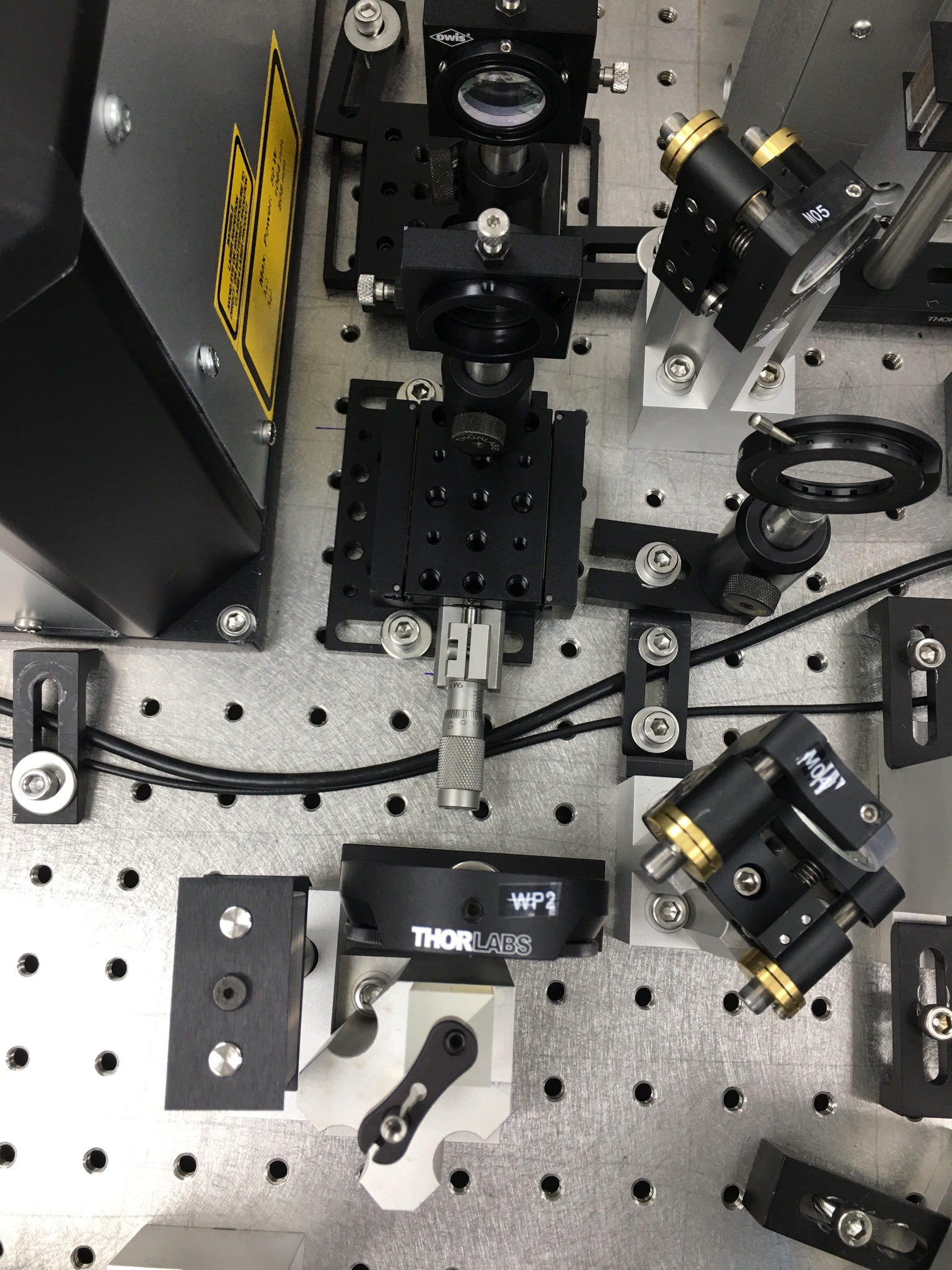
We began today by searching for a smaller micrometer to replace the rather large one on the 2nd mode matching lens mount. We found one in the PSL enclosure and Ed installed it, see 1st picture. We were then able to move the dog leg up by 1 row of holes, which cleared the interference with 70W amplifier output beam path.
We then mounted and installed 2 HR mirrors to re-direct the beam back online for the 70W amplifier. We used a couple of mirror pedestals from the IOO cabinet and used spare HR mirrors from the PSL spare stock. We then proceeded to align the beam. We started with the mode matching lenses, as the 2nd lens needed to be removed to install the shorter micrometer. We then realigned through the dog leg, using M08 and M34 to bring the beam up to the level for AMP_FI. We used a beam target to to align the beam down the required row of holes and at the right height. We then installed AMP_FI, AMP_WP02, and AMP_WP03 and checked that the beam was centered on them all. Using the same alignment target, we then used our 2 new HR mirrors to align the beam down the required row of holes for AMP_M01 and the new FE DBB beam path.
At this point we placed the Thorlabs beam profiler and spent some time optimizing the lens positions. The best waist we could get today was 365µm diameter horizontal and 344µm diameter vertical, likely due to the slightly increased optical path length due to AMP_FI, AMP_WP02, and AMP_WP03. This is close enough for rough mode matching, so we moved on. We roughly placed the 70W amp in its location so we could install AMP_M02 and mark its location for alignment purposes. We then removed AMP_M02 and the 70W amplifier and installed AMP_M01. Using the same alignment target, and the 2nd new HR mirror and AMP_M01, we aligned the beam down the row holes between AMP_M01 and AMP_M02. This is a very rough starting alignment for the 70W amplifier, likely not close to the final alignment but at least somewhere to start. We then installed AMP_M02 and AMP_M06, and placed beam dumps so all beams (leakage beams through AMP_M01 and AMP_M02 and the main beam reflected from AMP_M02) were blocked. Finally, we installed the 4 beam dumps for AMP_FI.
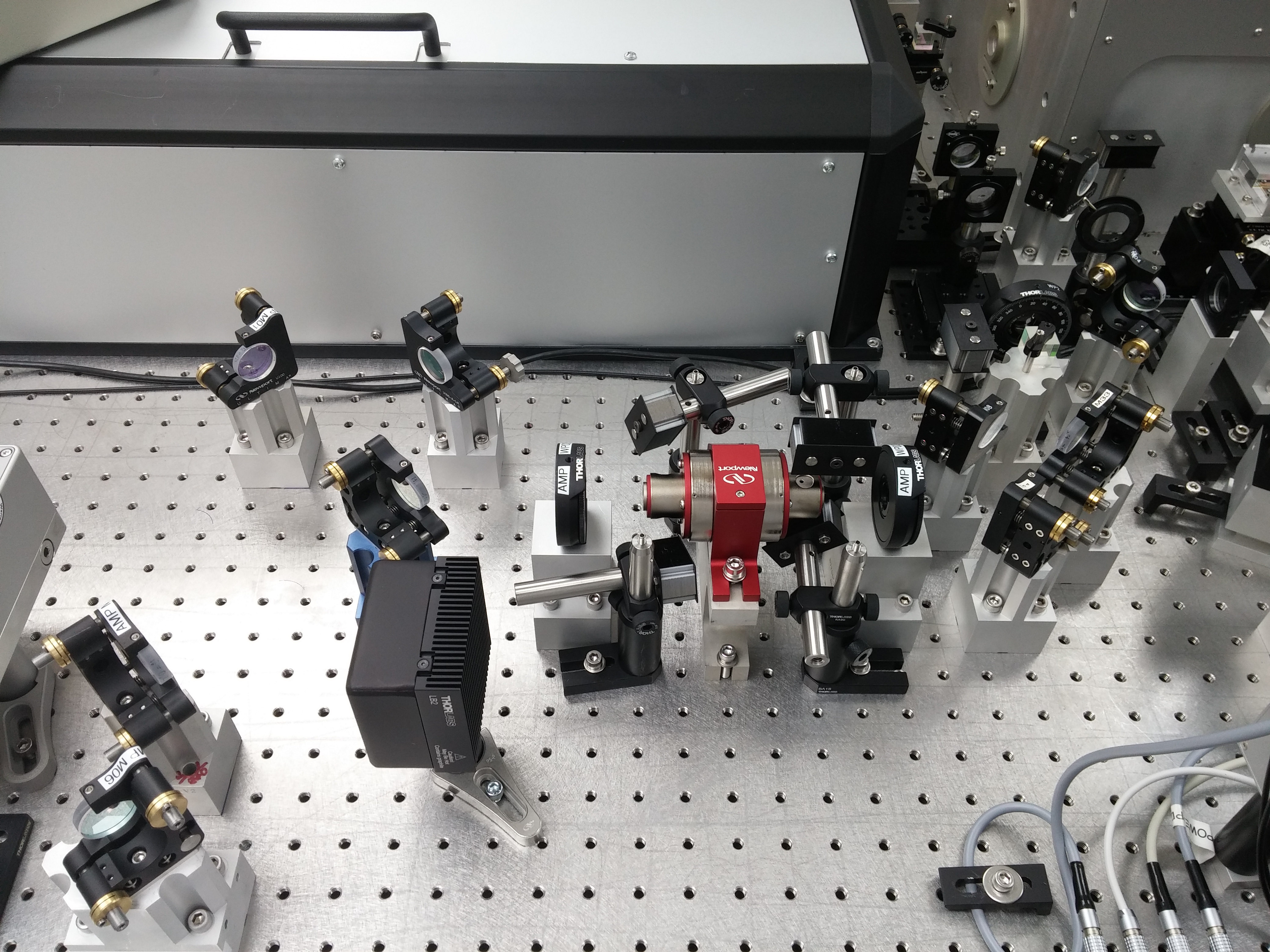
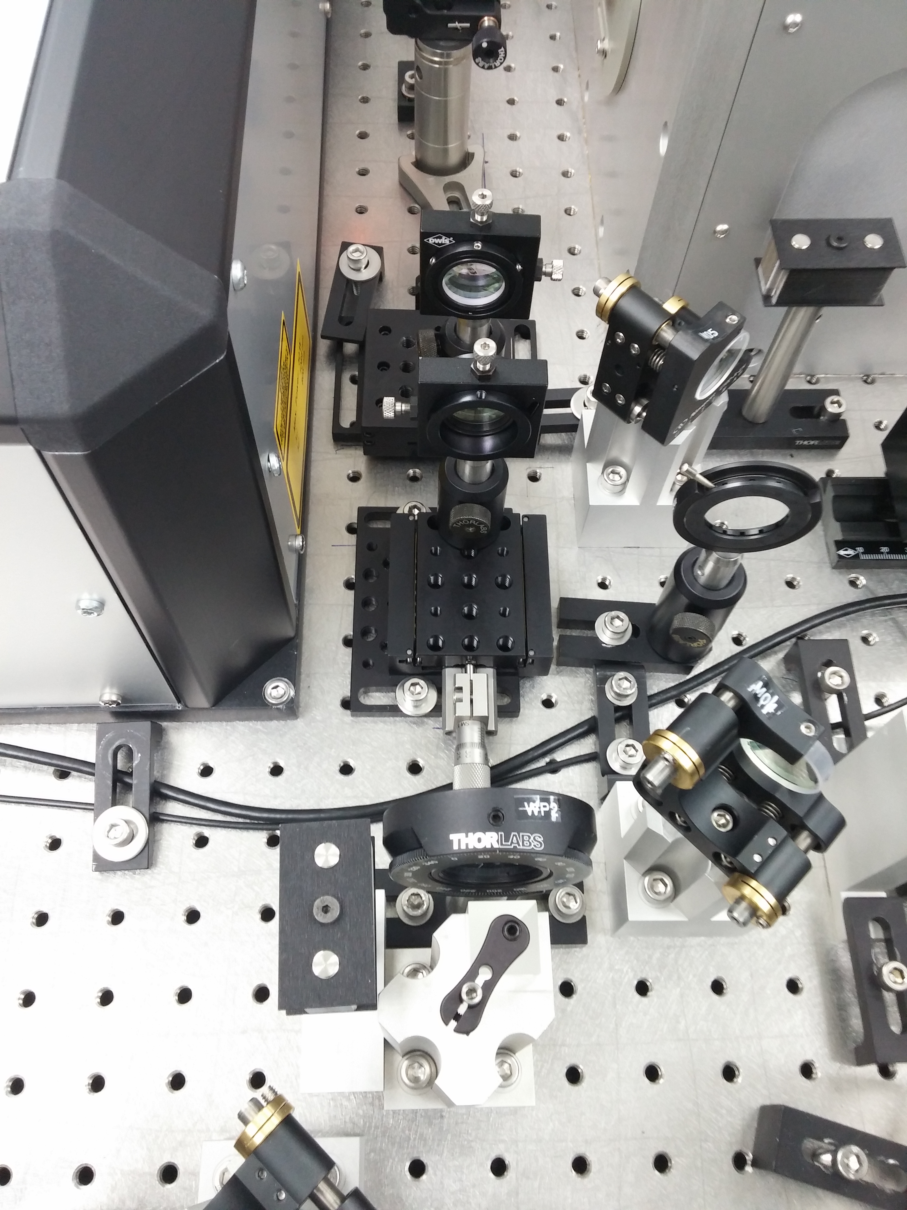
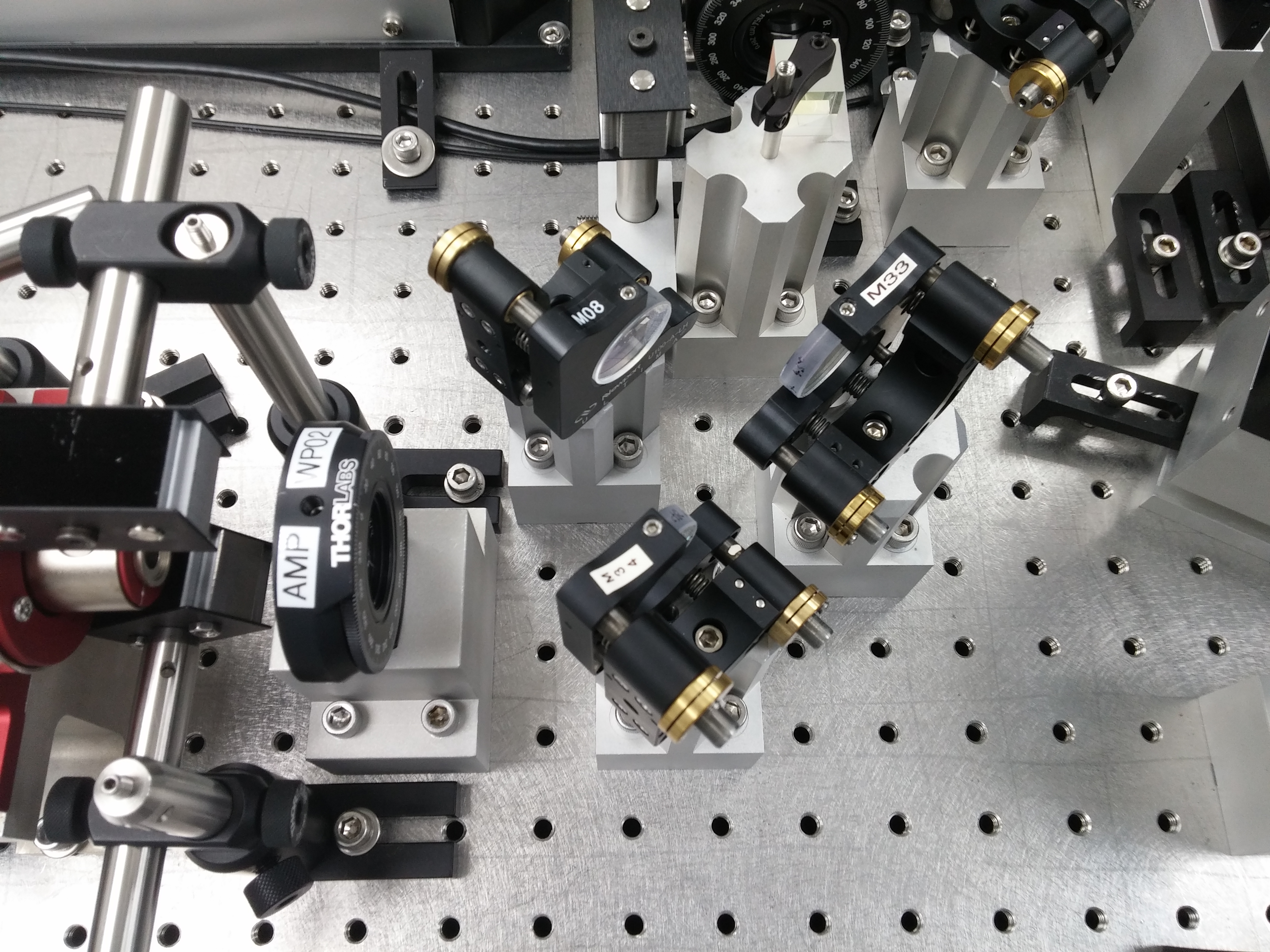
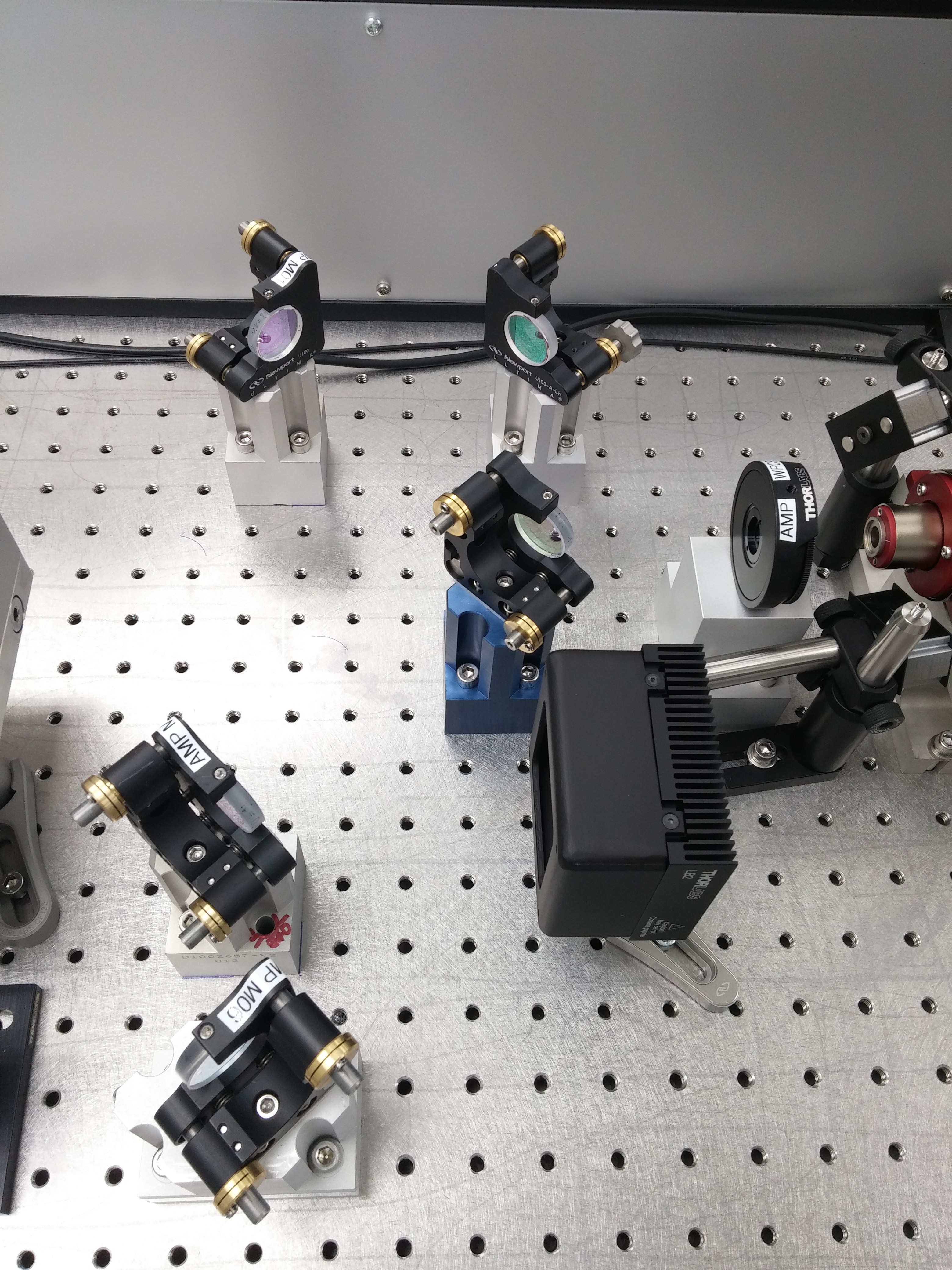
I've attached a few pictures of the new layout. The 1st shows the new, shorter micrometer. The 2nd is an overview shot of the pre-70W amp beam path. The 3rd shows the mode mathcing lenses, as well as WP02 and PBS02 in their new homes. The 4th shows the re-located dog leg and AMP_WP02 at the entrance to AMP_FI. The final picture shows AMP_WP03 at the exit of AMP_FI, the 2 new HR mirrors, AMP_M01, AMP_M02, and AMP_M06. The 70W amplifier will sit in-between AMP_M01 and AMP_M02.
Next week, Peter will begin the process of aligning the 70W amplifier and optimizing the mode matching.