[Rich A, Calum T, Luis S, Craig C, Koji A, Georgia M]
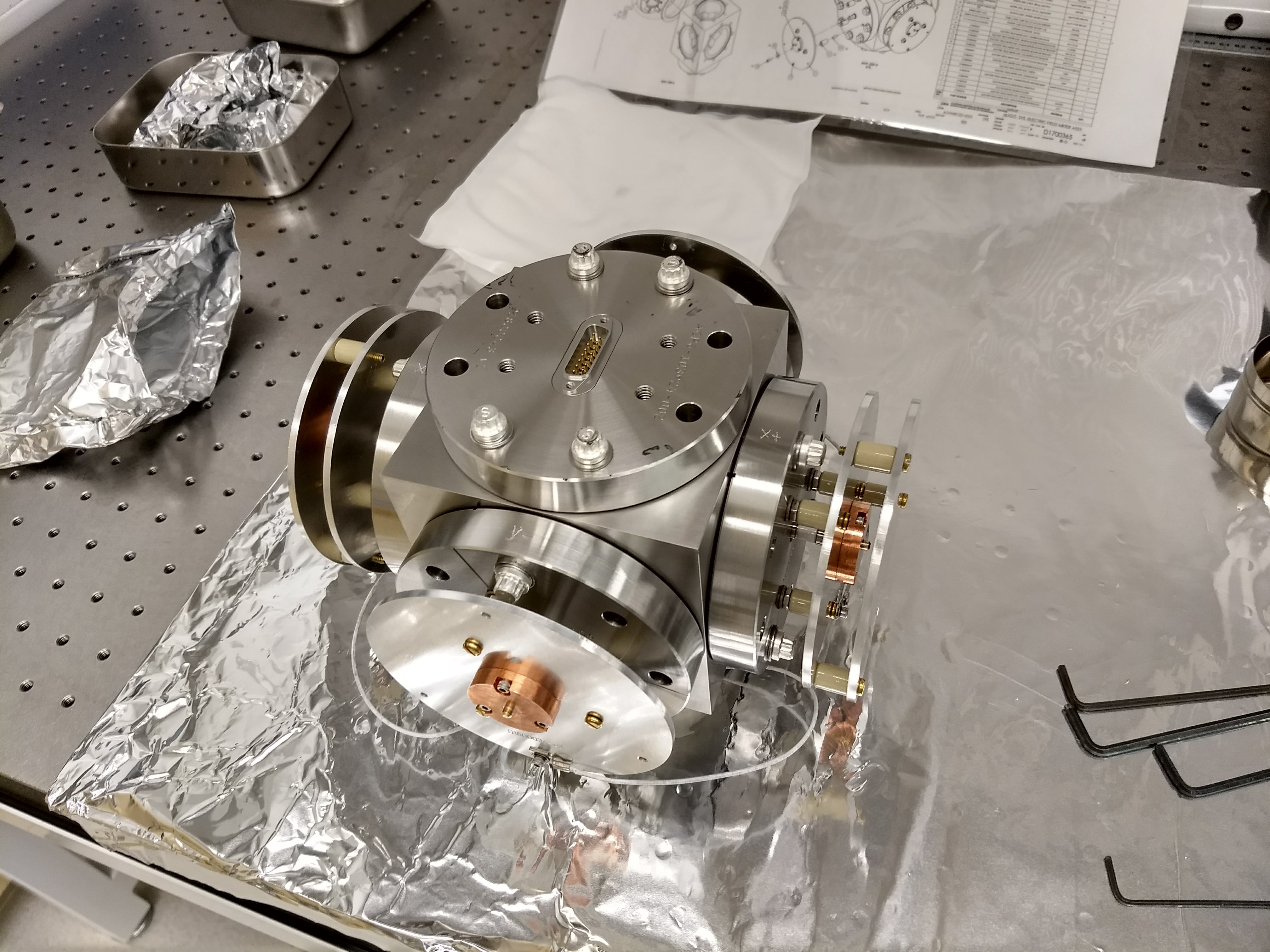
We have begun testing and characterising the electric field meter (EFM) brought over from Caltech. The first photo shows the EFM with the sensing plates shorted. All of this activity took place in the optics lab.
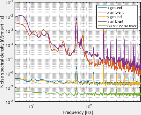
We used the SR785 to take noise spectra with the plates grounded, and of the ambient electric field (or acoustic environmental noise) for the X and Y plates. These spectra are shown in the first plot, the y data have 25 averages while the X data has one. The grounded spectra are in agreement (the 60 Hz harmonics are present in the blue x trace also) which makes sense, however I’m not sure why there is a significant difference between the x and y ambient spectra.
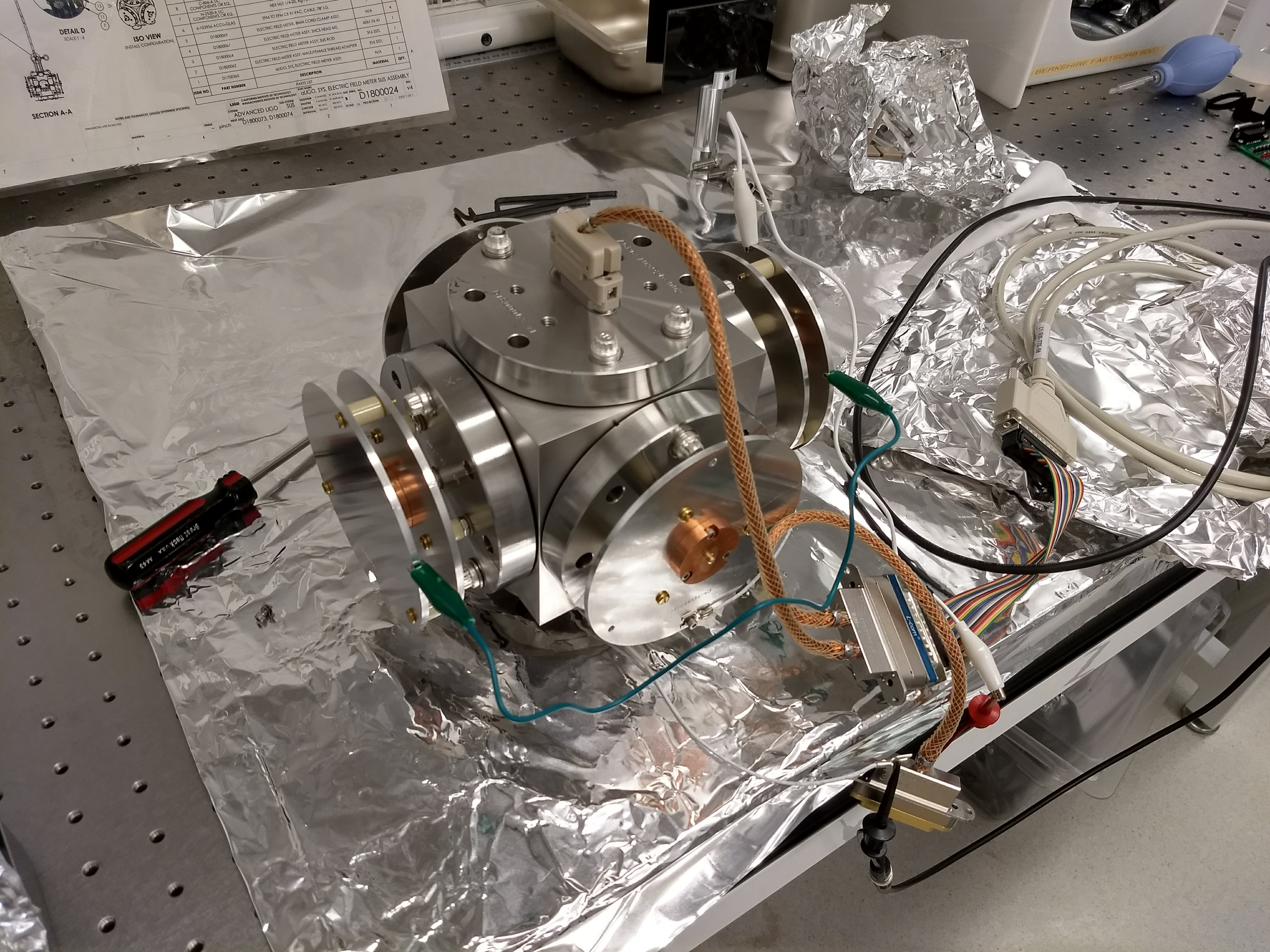
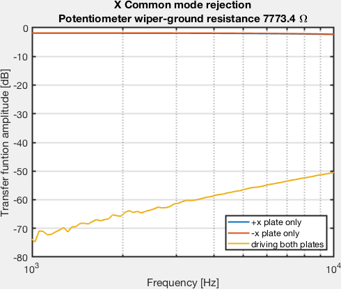
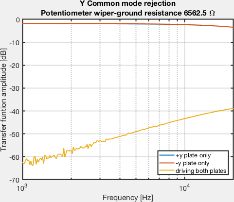
We then tuned the digital potentiometers, using the Arduino and Luis' code, to optimise the common mode rejection between the X+ and X- plates and the Y+ and Y- plates. To do this we attached the calibration plates over the sensor plates (but electrically isolated), and drove the common mode with a 1V signal. This configuration is shown in the second photo. The transfer functions to the common mode, and to a single plate, are attached for the Y plates. (the X data did not save properly and we did not have time to go back and get it. If I remember correctly we had ~47 dB of common mode rejection on the X plates, but please correct me if this is wrong). We achieved roughly 60 dB of common mode rejection between the y plates at 1 kHz, though this gets worse at higher frequencies.
Good that you got the device together so fast. The noise curves for x should be lower and the ones for y do not make sense. I am wondering about the calibration for electric field. You will need to take account of the copper button. The field between the calibration plate and the button will be higher than in the region between the plates outside of the button. The ratio of the fields in the two places will be in the inverse ratio of the gap space. One will need to estimate the induced surface charge on the sense plate by adding the contribution for the surface charge times area of the two regions with different gap spacing. If this is not done the field sensitivity of the device will be estimated as too high.
We retook the noise spectra, the ambiant Y trace is fixed, added the SR785 noise, and made the number of averages consistent (15).