jeffrey.kissel@LIGO.ORG - posted 14:46, Monday 16 April 2018 (41468)
H1SUSOPO Update: V2 OSEM problem traced down to AOSEM Flexicircuit, About to Replace It
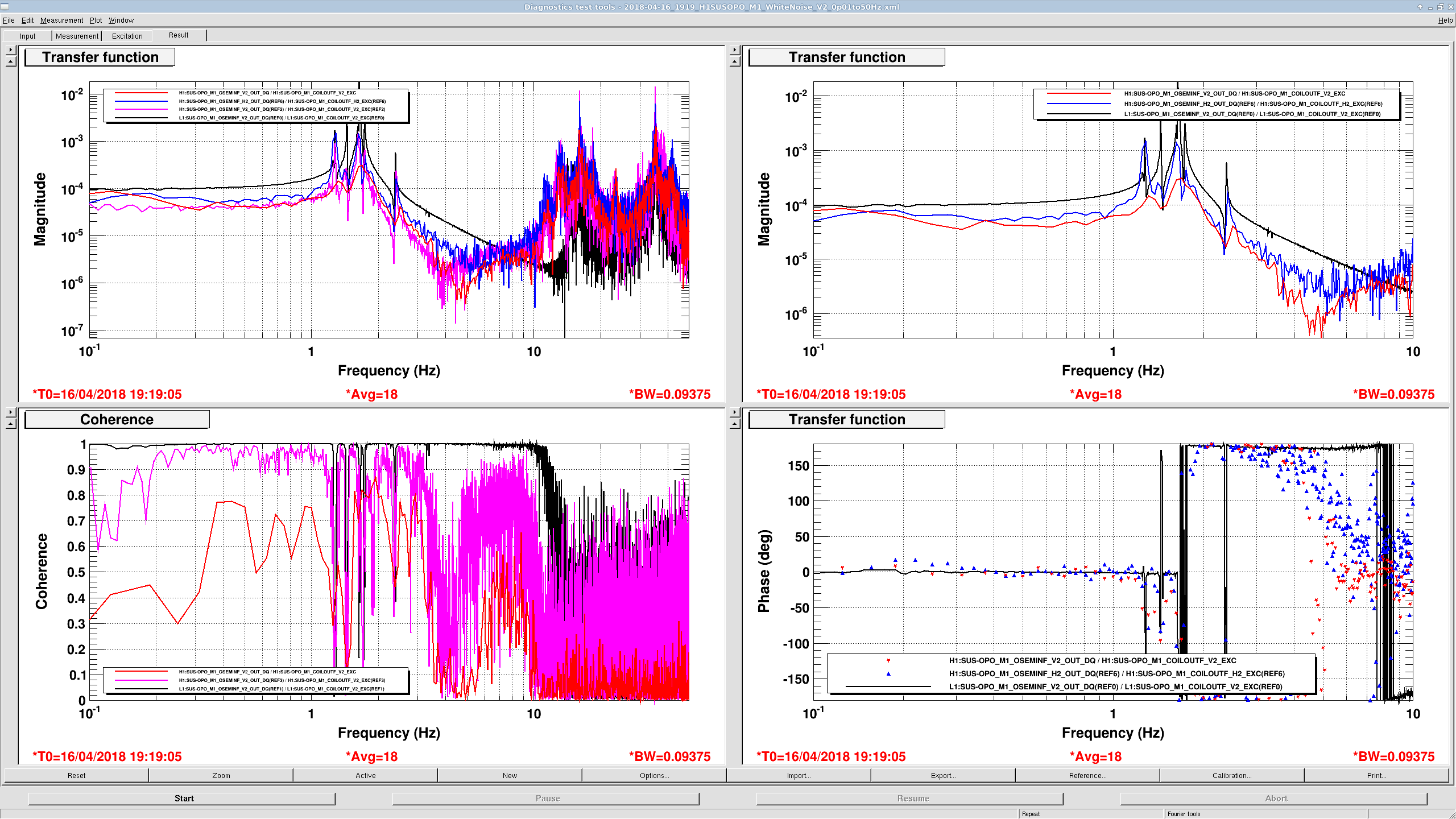
F. Clara, J. Kissel, T. Shaffer

We're back at the SUS OPO, trying to solve the last problem -- that the V2 OSEM shows a poor frequency response above its resonances (41256) that appeared between Feb 2018-02-27 and 2018-03-29. Because the poor frequency response has the same shape as the well-known sensor-to-actuator electronics coupling -- high-Q zero at 10-20 Hz -- (a.k.a. high frequency turn-ups a. la IIET Ticket 478040536 and 40613).

The below set of tests has convinced us that the H1 SUS OPO V2 AOSEM needs to be replaced, so we'll do that this afternoon.

We've therefore conducted several electronics tests this morning:
    - Ran the standard "ground loop" checks for shorting of the readout-chain's shield to ground: disconnected the H1V1H2V2 DB25 pin cable on the back of the US satamp, plugged a DB25 pin breakout board into the cable, then
        - Check for any short of pins to chamber ground:
             - run a lead from the closest chamber (in this we clipped to a bolt on one of the viewport blanks on the HAM5 side of the MCB Output Beam Tube between HAM4 / HAM5) into the Return (black) of the DVM
             - and check for continuity between any of the 25 pins and chamber ground.
             - There shouldn't be any continuity, and we found none.
        - Restoring the standard (black) lead into the Return of the DVM, check that pin 13 is continuous with the shield of the cable, and no other pin is continuous with ground. Only pin 13 should be continuous with the cable shield, that was true.
        - Check that no pin is unintentionally/unexpected continuous with any other pin. For this OSEM cable fed into a US Satellite Amplifier (D1002818), we expect pins 1 & 14, 4 & 17, 7 & 20, 10 & 23 to have low resistance because these connect the positive to negative legs of the OSEM coil (namely ~19 ohms). However, no other pins should be continuous with each other. We found all this to be true.

    - Scoured the in-chamber readout cabling, looking for potential electrical grounding between the readout cable and the ISI or chamber walls. We found nothing obviously suspicious, and no change in frequency response after several moves.

    - TJ physically disconnected the micro-D connector of the Quadropus (D1000239) from V2 OSEM at the OSEM, then re-seated and re-tightened the connection. No change in response.

    - TJ physically disconnected the DB25 connector of the Quadropus from the Table Cable Bracket (D1001346), then re-seated and re-tighted the connection.
    - TJ found that one of the screws securing the flexi-circuit (D0901252) to the V2 AOSEM assembly (D0901065) was loose, so he tightened it.
        After these two changes test, we saw a significant increase in the zero frequency
    - Further tightening and loosening of the AOSEM's flexi-circuit screws continued to have an effect on the zero frequency, namely tighter made it *better* but not perfect like all other OSEMs.

    - As a final nail on the coffin of the flexi-circuit of the V2 OSEM, we swapped micro-D connectors of the Quadropus cables between H2 and V2, and readout each the OSEM with the opposing signal chain -- taking a transfer function of V2 with the H2 electronics chain, and of H2 OSEM with the V2 electronics chain.
        V2's electronics chain reading out H2 showed an entirely normal high-frequency response [first attachment]. H2's electronics reading out V2 showed a similar bad response [second attachment].

Attachment Key:
[first attachment]
    - black : Perfect (in-vacuum), fully functional reference from L1 SUS OPO
    - magenta : Before today, clearly identified badness (high-frequency zero) with V2 electronics reading out V2 OSEM.
    - red : Fully functional, today, with V2 electronics reading out H2 OSEM. final nail in the coffin

[second attachment]
    - black : Perfect (in vacuum), fully functional reference from L1 SUS OPO
    - blue :  H2 electronics reading out V2 OSEM Still bad, final nail in the coffin
    - magenta : Before today, clearly identified badness (high-frequency zero) with V2 electronics reading out V2 OSEM.
    - red : During today, after tightening flexi-circuit screw.
Images attached to this report