georgia.mansell@LIGO.ORG - posted 18:46, Thursday 19 April 2018 - last comment - 13:59, Saturday 28 April 2018(41559)
Electric Field Meter testing with viewport-mounted capacitor
[Robert S, Georgia M]
We tested the electric field meter (EFM) with a viewport-mounted capacitor which Robert has previously used to observe electric field coupling to DARM. We measured the fields associated with the capacitor in both the x and y axes of the EFM.
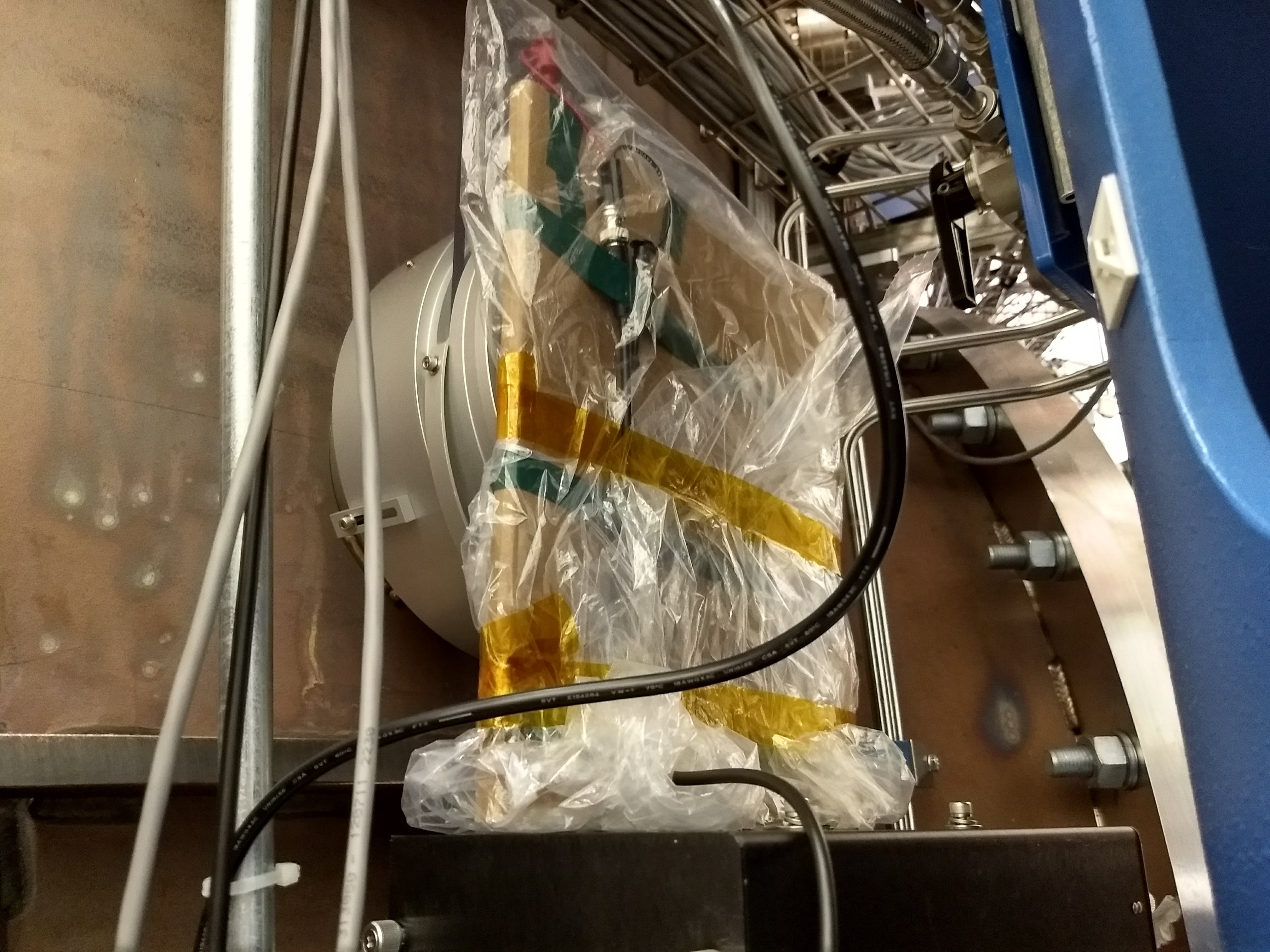
The capacitor is mounted on the outside of the viewport (photo 1) and driven with 10V pk-pk at 190 Hz (and later 211 Hz).
We amplified the differential EFM signal with a SR560 preamp with a gain of 100, to increase the EFM noise floor over the ADC noise, and read this into a PEM CDS channel (channel 14 on the PEM chassis at the bottom of the TCS rack, channel H1:PEM-EX_ADC_0_13).
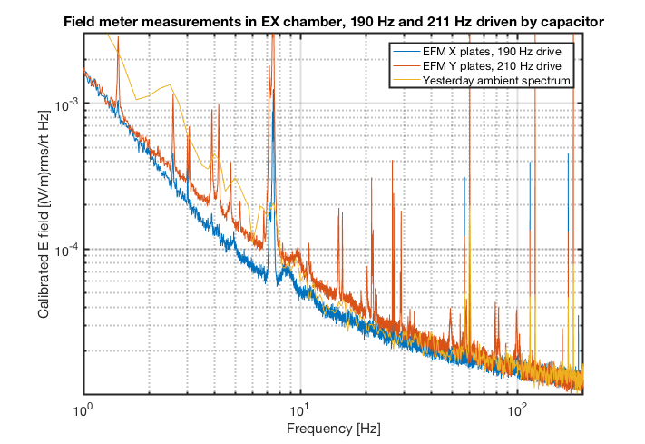
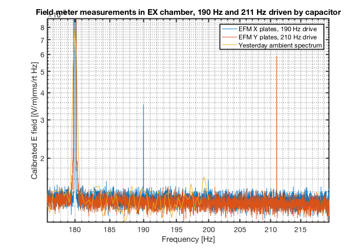
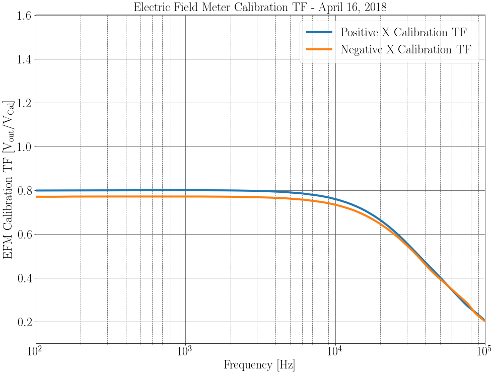
To calibrate these spectra we used 65536 cnts = 4 V, and 0.8 V_{drive}/V_{out} of the EFM, factored in the SR560 gain, and divided by the distance from the sensor plates to the body of the cube. I'm attaching some preliminary spectra. The first spectrum is for comparison of the calibration from yesterday (which used SR785 data rather than CDS-read data), the second is zoomed in to the frequencies we drove with the capacitor. Analysis is ongoing!
Images attached to this report
Comments related to this report
Calibration of the field meter does not need knowledge of the input capacitance. With the calibration plates, the electic field
on the sense plate is simply  E(cal)= V(cal)/d where d is the calibration-sense plate separation. If you want to improve the accuracy you will need to account for the thickness of the copper disk on the sense plate and a few percent error due to the fringing field.

The current sensitivity curves are pretty close to the ones measured in the prototype. How did you handle the factor of 2 due to the two plates on each coordinate and the output which is the difference?
We were a little confused about how to calibrate the EFM. It's not such an easy problem as it first seems.Calibration Plate Voltage to Electric Field TF
V_cal refers to the potential difference between the calibration plate and ground. Ground is connected to the body of the EFM. The sensor plate is kept isolated and should be at voltage V_sense = V_cal * d2/(d1 + d2) where d1 is the distance between the cal plate and sensor plate, and d2 is the distance between the sensor plate and the body. If we assume that the electric field E_cal is constant over the entire EFM, then I think we ought to be using the total distance d = d1 + d2 between the calibration plate and body for E_cal = V_cal/d. d1 = 1/2 inch = 1.27 cm, and d2 = 5/8 inch = 1.59 cm, so d ~ 2.86 cm and E_cal/V_cal = 1/d ~ 35.0 (V/m)/V using this method. However, we became concerned about the geometry of the EFM affecting this result. There is a copper disk which connects the sensor plate to the sensor pin, and there are a bunch of large screws between the sensor plate and the body. We decided to compute an "effective distance" using the capacitances we measured between the cal and sense plates (~11pF), and the sense plate and the body (~19pF) via E = Q/(2 A e0), where A is the area of the plates (~0.01 m^2), e0 is the vacuum permittivity, and Q is the charge on the cal plate. Q = C V, so we can recover E/V = C/(2 A e0) = 1/d, so our effective distance d = (2 A e0)/C, where C is the total capacitance between the cal plate and the body (~7pF). Using this method, E/V ~ 38.9 (V/m)/V, not much different than our result from 1/d. This is the number we used to calibrate from V_cal to E_cal. I don't know what value was used for the initial prototype.Differential Amplifier Factor of Two
We did not account for this. We did not understand that the EFM body was grounded, so that the body absorbs the E_cal field by inducing charge on its near face. In the presence of a large external electric field both sense plates will have voltage induced, so we will get twice the response from the EFM differential amplifier circuit. We measured a TF from V_cal to V_out where V_out is the voltage output of the EFM differential amplifier circuit, and got V_out/V_cal ~ 0.8 from 5 kHz down. This should be multiplied by 2 for the V_out/V_external TF.Corrected Plots
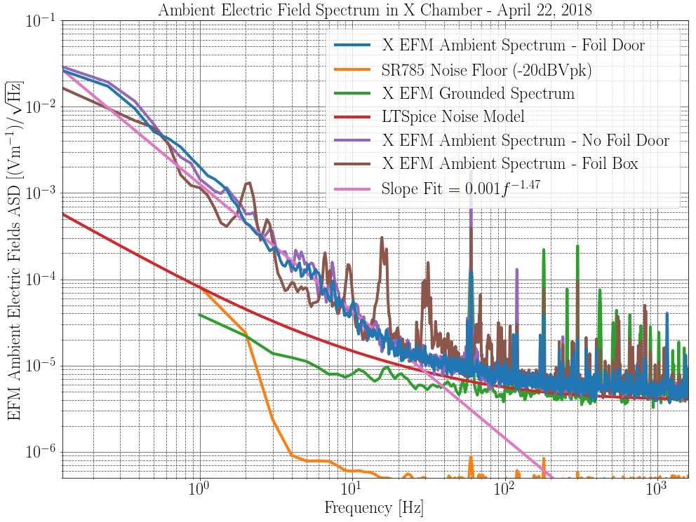
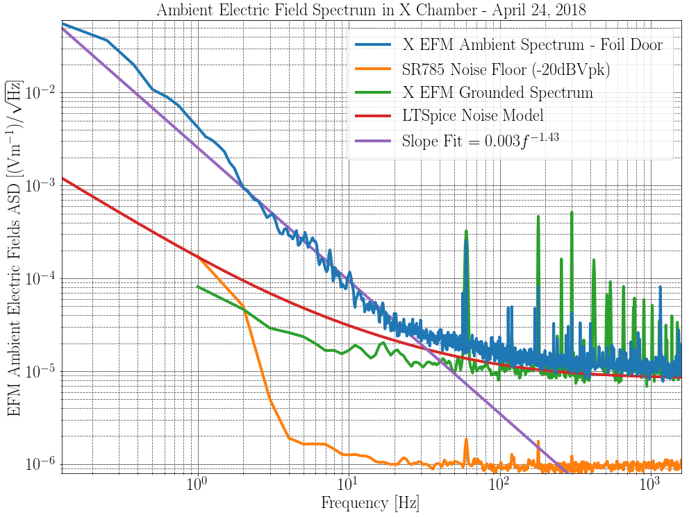
Plot 1 is the newly calibrated ambient electric field ASDs recorded by the EFM. Plot 2 is the V_out/V_cal TF.
Images attached to this comment
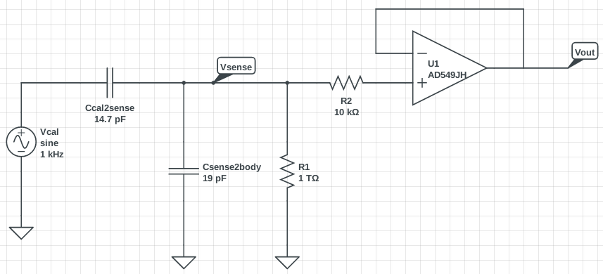
We (the EFM calibration team) never understood that the sensor plates are virtually grounded by the op-amp inside the EFM until we saw Figure 2 of T1700103. This is why we kept insisting that E = Vcal/d should use d = distance between calibration plate and the EFM body: we thought that the sensor plate was an floating conductor. I fixed our calibration to account for the grounded sensor plates. If I use E = Vcal / d where d is the distance between the cal and sensor plates (d ~ 1/2 inch ~ 1.27 cm), I get. If I account for the copper plate and fringing fields by using our measured capacitance between the calibration plate and sensor plate (C ~ 14.7 pF), I get
(Area A of the plates is ~ 0.01 m^2). This is the E/V calibration I used for the plots below. Also included was our cal volts to EFM output volts measured calibration value of 0.8 V/V. This was multiplied by two to account for the differential response of the EFM to external electric fields, and inverted to give
. Unfortunately, with this corrected calibration our prototype EFM spectrum is worse than we originally thought. In fact, it's worse than your final prototype spectrum from T1700569 by about a factor of two. I am not sure why this should be the case. Rich's LT Spice model has a output voltage noise floor of about 200 nV/rtHz at 200 Hz upward. In your Figure 2 of T1700569, you report a Vn of 110 nV/rtHz, so maybe this result is correct.
Images attached to this comment
The calibration is simpler than you make it. With the cube grounded and the calibration plates
mounted on the sense plate, the electric field induced on the sense plate is E = V(cal)/d (with small
correction for fringing and the copper plug). If you want to make a model for the calibration to predict
the sensitivity that is more complicated and requires knowledge of the capacitances and the potentials
between the sense plate and the cube.
Craig, you refer to T1700103 figure 2 to understand the virtual ground. This is not the correct schematic for the implementation of the EFM that was recently built. Each EFM input is simply 10^12 ohms to ground (in parallel with the sense plate capacitance). There is no virtual ground provided actively by the operational amplifier.
Final note on the EFM calibration. Conclusions:After a discussion with Rai and Rich we determined the correct calibration is
where
is the driven voltage on the cal plate,
is the induced voltage on the sense plate, and
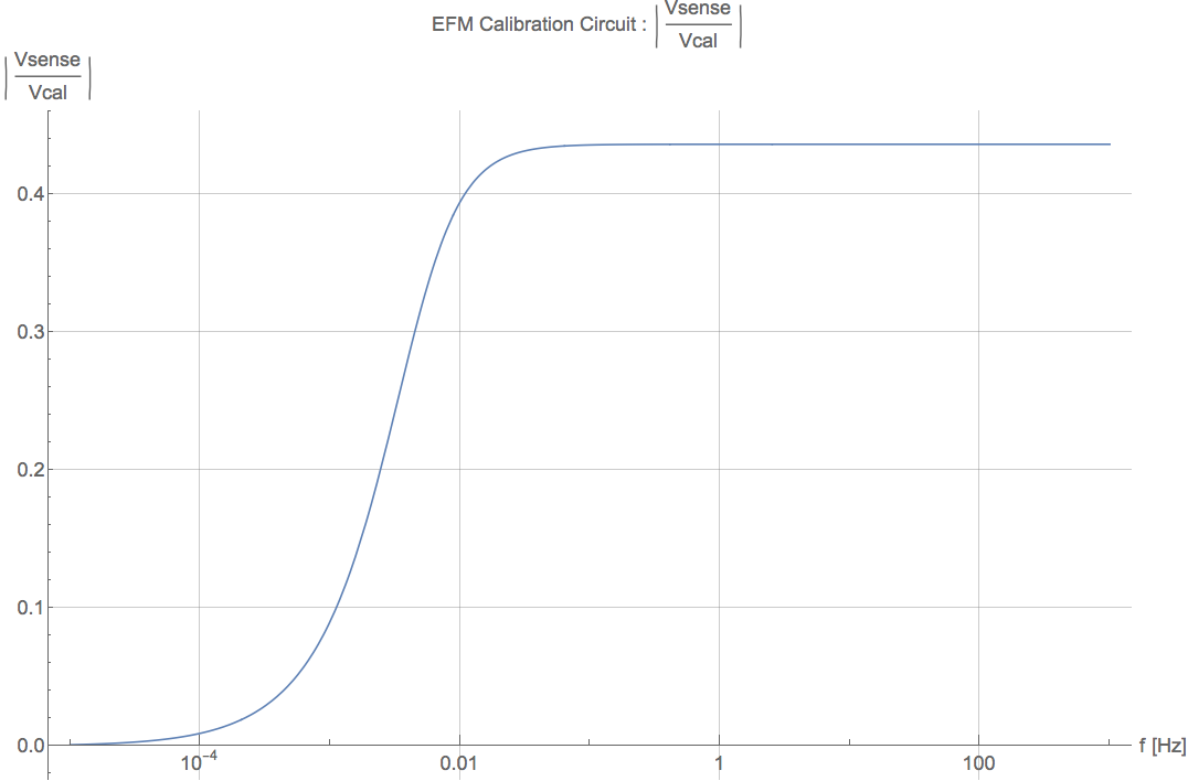
is the distance between cal and sense plate. We need to know the voltage induced on the sense plate. To do this I simulated the circuit in the first picture. Again, we measured the capacitance between the cal and sense plate to be 14.7 pF, while the capacitance between the sense and body was 19 pF. I found
above 10 mHz. Solving for
gives the result above. The final plot is the correctly calibrated ambient electric field spectrum.
Images attached to this comment
I am very sorry for having generated all this confusion. The sense plate is not a virtual ground, that was the case in earlier circuits. In this
circuit the proper formulation for the electric field on the sense plate from the calibration plate is

          V(cal) - V(sp)           V(cal) C(cal-sp)
E(cal) = ---------------- = ----------------------------------  So, the calibration field is smaller than in the case for the sense plate held
            d(cal-sp)       d(cal-sp)(C(cal-sp)+C(sp-allelse))

at ground potential which makes the field meter more sensitive. Which is what you found. The error is purely mine and not Rich Abbott's or any
of the people in the electronics group. It comes from my not thinking about the calibration again after the circuit was changed from one type
to another in my lab.