Fil, Georgia
Conclusion:
We believe that the ETMY LR ESD quadrant is disconnected somewhere in-chamber.
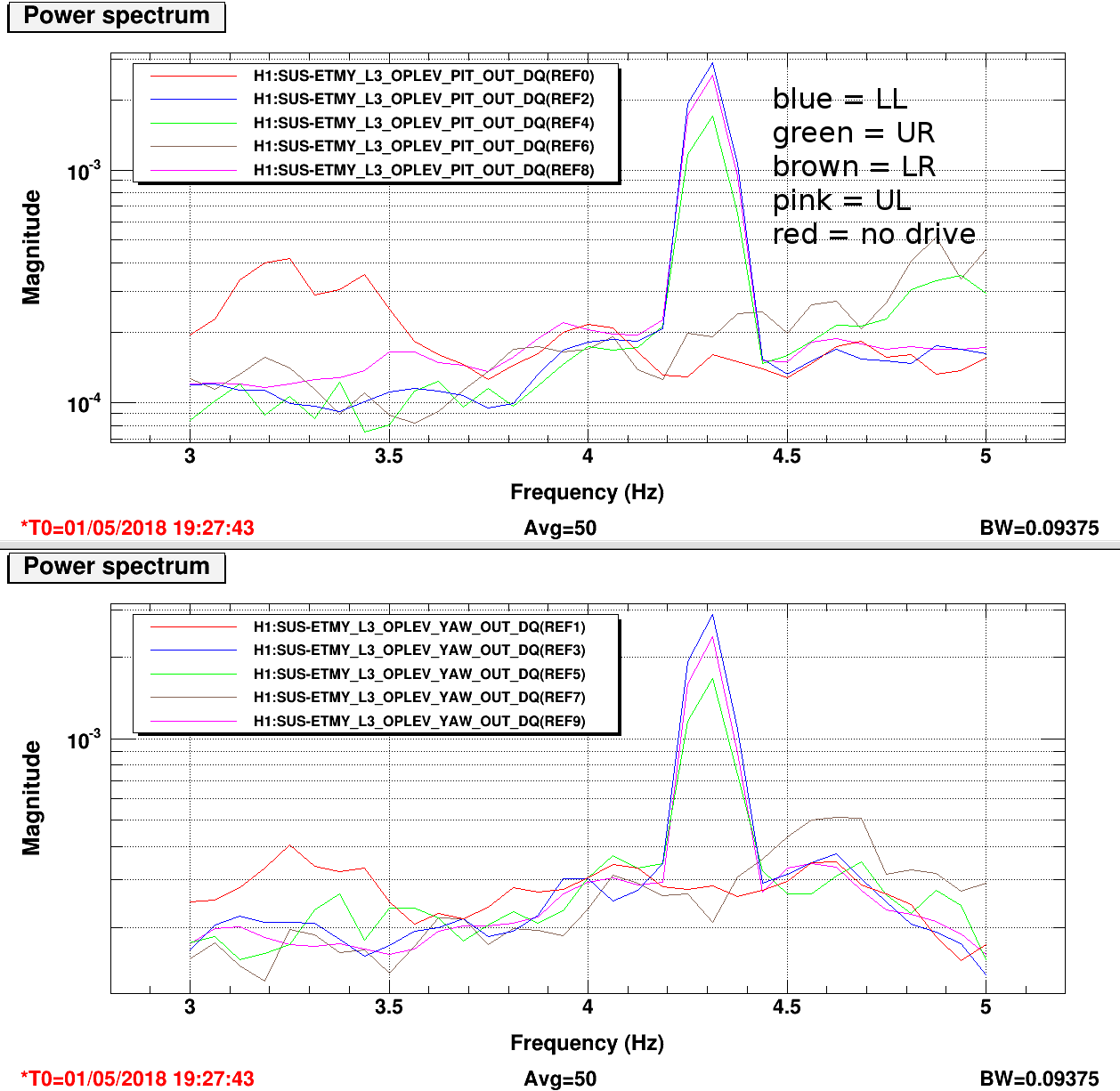
After problems with ESD-optical lever charge measurements, I tried to confirm that we are actually driving the LR quadrant by driving the individual ESD quadrants with a 4.3 Hz sine wave (30000 counts amplitude, with 100000 counts on the bias) and looking for the response on the optical lever pitch and yaw. A response was seen while driving the other 3 quadrants, but not the LR quadrant (see attached screenshot).
Fil and I went down to EY to check all the electrical connections outside the chamber. Between the HV chassis and the chamber feedthrough there is a resistor box and a pigtail connector. Everything outside the chamber is working as it should.
- We checked the connections in the resistor box, some connectors were loose but everything was connected. (Note the resistors in the box are actually bypassed, as their function (to limit current to the ESD electrodes) is now done inside the chassis. The box remains as an elaborate SHV-SHV connector.
- We drove the LL quadrant, with this signal hooked up to the LL, UL and LR quadrants at the resistor box, and only saw a response in LL and UL, confirming that we are driving up to the pigtail.
- We reseated the pigtail connector, repeated the above test, and saw nothing while driving the LR quadrant.
- Finally, we replaced the pigtail with a spare, and again saw nothing while driving the LR quadrant.
FRS ticket filed; ticket number 10543.
We have seen this type of behavior before. If it's the same issue as seen at LLO, the problem is associated with the last connection in the ESD chain right at the union of the coaxial Accu-Glass cable coming ultimately from the vacuum flange, to the thin biomedical wire used to actually make the connection to a segment of the ESD.  The issue relates to the fact that the connectors were not assembled correctly somewhere in the distant past.  When the two sides of the connector are mated together, either the pin or the socket of one connection is forced back into the connector instead of forming a socket-pin connection.  This was due to the use of the incorrect PEEK backing part inside the connector.  The recipe for a complete fix of this issue is to take apart the connector next to the optic and re-terminate it in-situ with the proper backing part.  Not for the faint of heart, but Carl Adams at LLO has already done this.

Alternatively, there is always the temptation to wiggle the connector around until things make contact again.  For worst results, try that.
Relevant drawing for the ESD wiring chain: D1400177, which admittedly starts from pg 15 (plus monitor stuff on pg 11) of the QUAD ETM wiring diagram D1002741-v9.

Translating between Georgia and the drawing, the "pigtail" referred to above is the chamber side of HV Coax Bundle on pg 5 that emanates from the Strathclyde high voltage driver output.

Further, the drawing indicates that A pasternack PE9337 SHV barrel should be used for the connection between this UHV bundle and the 5-way coax connection to the chamber feed through (since v4 of the drawing), but as indicated above, we've instead by-passed the resistors in the current limiting assembly, D1201288, shown way back in v3 of D1400177-v3) (which, naturally, incorrectly points to D1500164, an accelerometer dog clamp).