[Marie, Aidan, Alexei, Dan]
Summary
Yesterday we improved the LED return beam from the ETM to the point at which we could attempt to characterize the noise of the Hartmann sensor and run a measurement of the ring-heater. This was predominantly achieved by (a) improving the mode-matching of the LED beam to the in-vacuum optics and (b) imaging of the ETM.
Details
Our first approach yesterday was to try optimize the imaging of the ETM on the HWS camera. This was attempted using the usual method of injecting a YAW oscillation (10urad amplitude, 0.03Hz period) into the ETM and monitoring the centroid of the return beam on the Hartmann sensor. The amplitude of the oscillation on the centroid should go to zero when the Hartmann sensor is at the conjugate plane of the ETM. However, we moved the Hartmann sensor longitudinally over a range of approximately 30cm and saw no noticeable change in the amplitude (which remained at 10 pixels, or 20 pixel pk-pk) on the Hartmann sensor.
Additionally, we measured the distances (as best we could) between the various optics in the Hartmann sensor path. The results are:
| Parameter | Measurement | Design [T1000717] |
| Source to Lens 1 | 0.762 m (+/- 5mm)* | 0.9036m |
| Lens 1 focal length | -0.5589m (specification) | -0.5589m |
| Lens 2 to Lens 2 | 1.0858m (+/- 5mm) | 1.079m |
| Lens 2 focal length | +2.2361m (specification) | +2.2361m |
| Lens 2 to Lens 3 | 0.6112m (+/- 5mm) | 0.610m |
| Lens 3 focal length | +2.2361m (specification) | +2.2361m |
* The distance from the Hartmann sensor to Lens 1 was estimated to be approximately 2"-4" shorter than this. Nominally, the source and the Hartmann sensor should be at the same distance from Lens 1.
The first take-away from this was the Hartmann sensor appeared to be approximately 20cm - 25cm too close to Lens 1.
The input beam from the LED source was approximated by a beam 4mm radius and converging to a focus 1.5m from the source, see TCS eLOG 210. Knowing this, we could inject this beam into a paraxial beam propagation of the full ETM/TMS system to estimate the beam size through the system. The remaining relevant parameters are reproduced here from T1000717-v5.
| Parameter | Value |
| Lens 1 to TMS secondary mirror T2 | 4314mm |
| Secondary mirror, T2 ROC | -200mm |
| Secondary mirror, T2 to Primary mirror, T1, distance | 1902.6mm |
| Primary mirror, T1 ROC | 4000 mm |
| T1 primary to ETM HR distance | 1429 mm |
| ETM ROC | -2245m |
| ETM ROC apparent (as viewed from outside)* | -1537m |
* Assuming n = 1.4607 for 532nm.
Beam propagation (with 1.5m convergence)
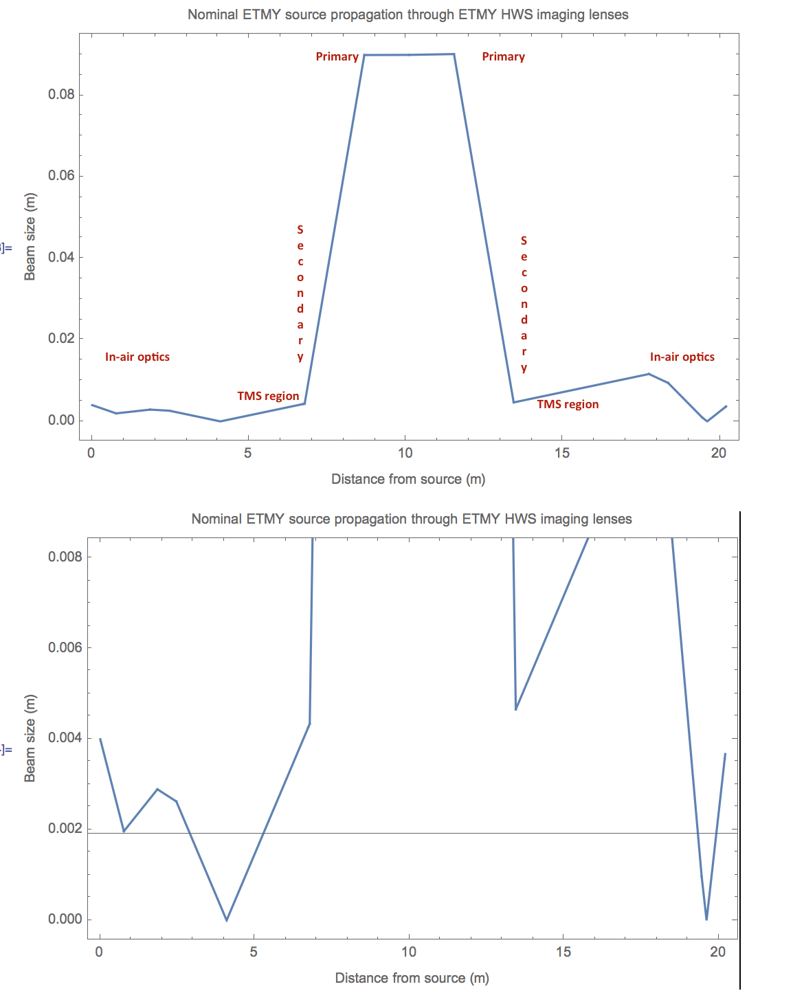
We propagated the nominal input beam (4mm radius, +1.5m focal point) through a paraxial beam propagation (it's not a remotely Gaussian beam) from the source through to the ETM and then back to the Hartmann sensor. The results are shown below. Inside the vacuum system, the optics are all (mostly?) 1" diameter on the TMS table. A 1" diameter optic at 45 degrees has a clear aperture horizontally of the order of 16mm across. So, the beam propagation is also shown with the scale limited to 8mm. This makes it very obvious that the return beam is likely significantly clipping horizontally on the TMS & in-air optics.
The return beam looked something like this:
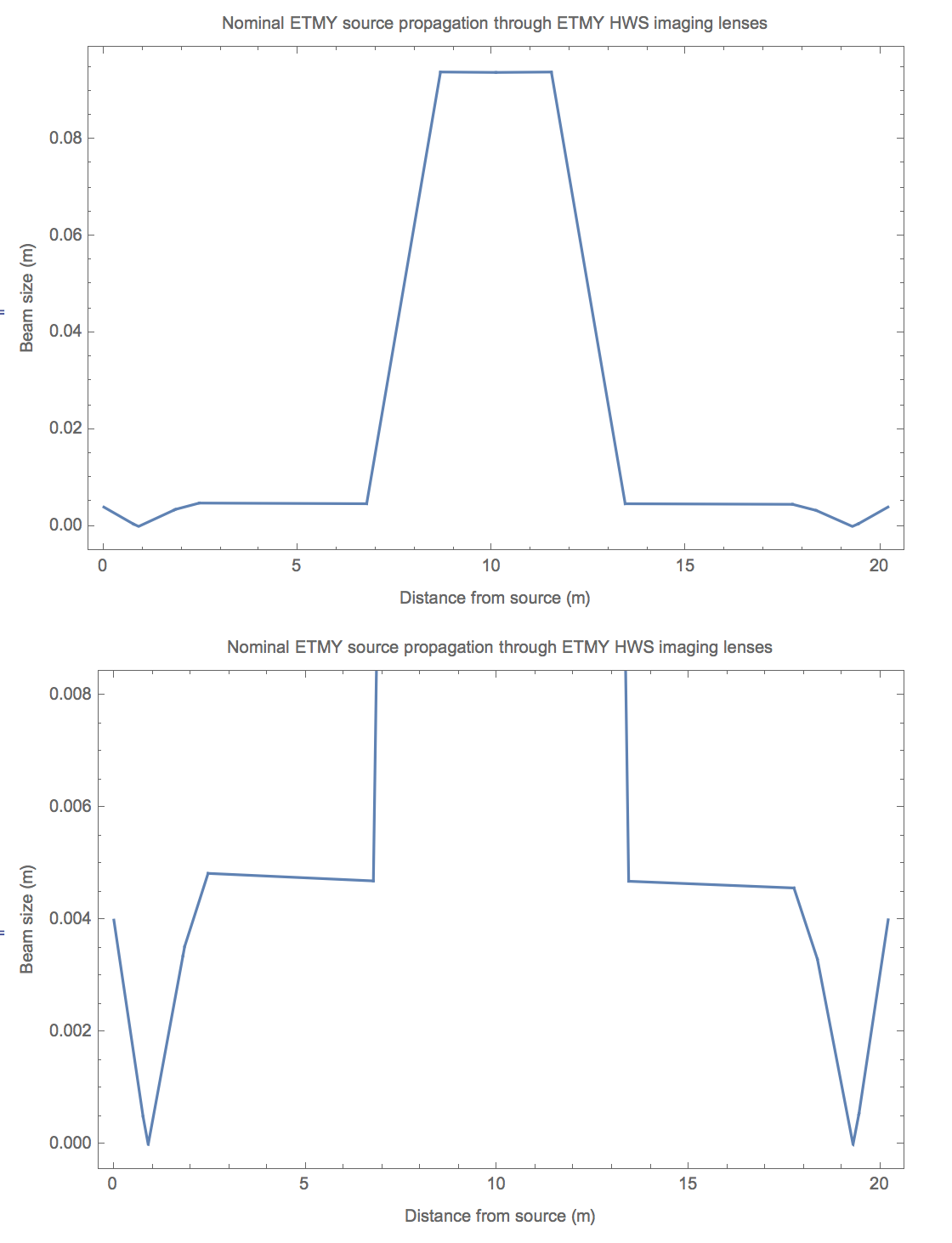
Beam propagation (with 0.87m convergence) - improved mode-matching
I changed the input beam to 0.87m convergence. And the model suggested significant improvement in the nominal mode-matching. It suggests that the input and return beam are well balanced, that we have a good retro-reflection from the ETM HR surface and that we are not likely to be clipping on any of the 1" optics. The beam size is approximately a factor of 1.7x smaller than the limiting aperture size.
This change was facilitated by adding a 9mm spacer to move the 1" diameter, 125 mm focal length lens further from the 20 mm lens inside the fiber launcher.
Initial system: S_input - S_lens = S_output
S_input = S_output + S_lens = -1/1.5m + 1/0.125m = 7.33 diopters
Therefore input beam looks like it's coming from a point 1/S_input = 0.1363m behind lens
S_out_target = -1/0.87m
S_input_target = S_out_target + S_lens = -1/0.87m + 1/0.125m = 6.85 diopters
Therefore input beam needs to like it's coming from a point 1/S_input_target = 0.146m behind lens.
Therefore, we need to add another 9mm or 10mm spacer to move the lens forward.
We added a 9mm spacer.
Improved return beam
Following this we optimized the alignment of the return beam by eye, and also moved the Hartmann sensor back approximately 20cm to move it closer to the conjugate plane of the ETM HR surface.
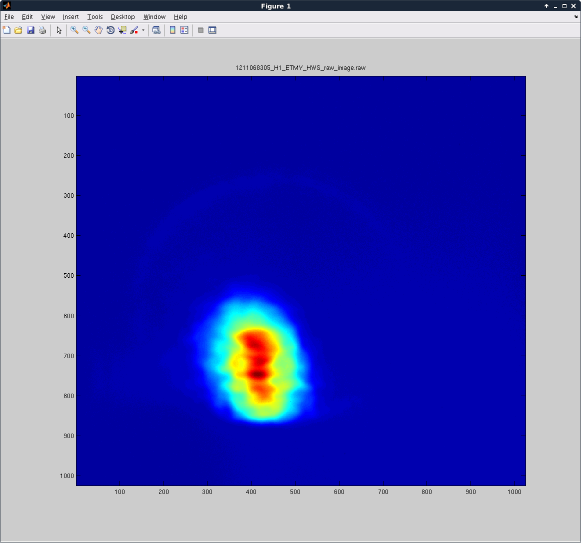
The return beam started to look much cleaner. There is still some high spatial frequency noise on it and it looks like it might be clipping somewhat, but it now appears to show the 220mm diameter annular reaction mass hole. The beam was less elliptical and more circular (but not completely). We could also close the iris down in front of the fiber launcher and see a crisp circle of light on the Hartmann sensor (which we couldn't before).
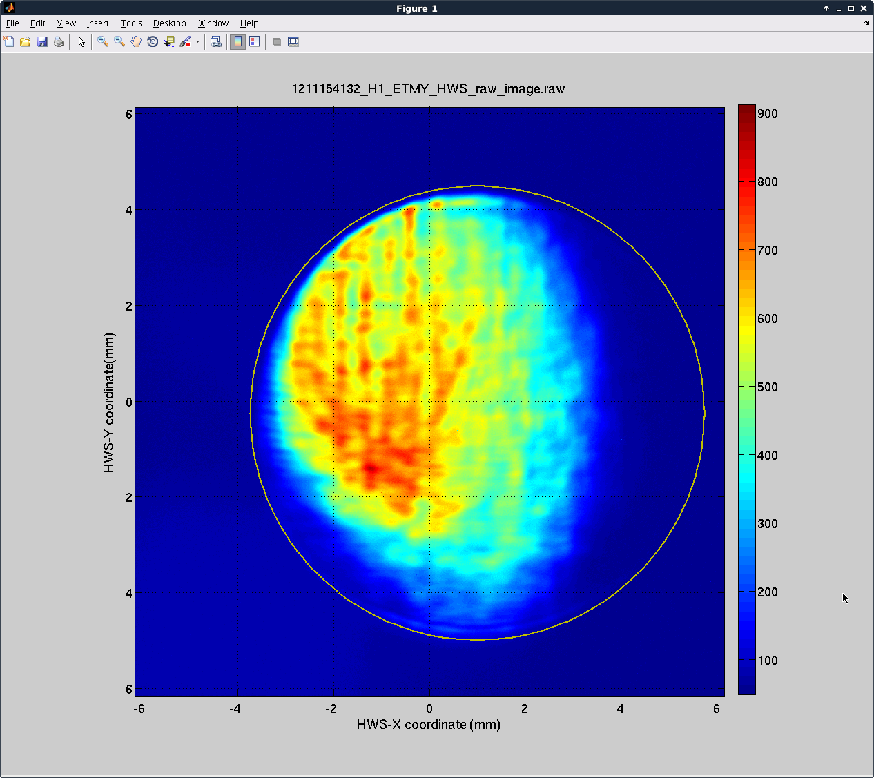
The improved return beam looked like this. The magnification with the measured values is estimated to be 23.5x. I demagnified the annular reaction mass hole [D1500163] (diameter = 222.5mm) by 23.5x and drew it on the return beam (yellow line). I strongly suspect that the circular aperture in this image is the AERM hole.
Hartmann sensor measurements
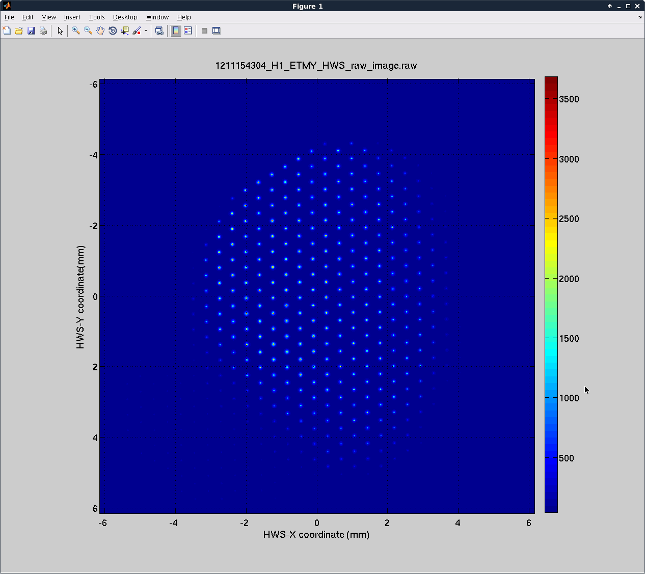
Given that we were getting toward the end of the day, we decided to install the Hartmann plate and run the Hartmann sensor overnight. We initialized the code and saw approximately 300 spots - indicating good coverage. The spherical power seemed to fluctuate around +/- 4E-6 diopters. We also set up the ring-heater to run. We'll summarize these results in another aLOG.
In conclusion, there is definitely room to improve (a) the input beam size, (b) the mode-matching, (c) the alignment to the ETM and (d) the imaging onto the Hartmann sensor. However, these results are very encouraging.
The Hartmann sensor beam looks like this: